1995 JEEP YJ fuel cap
[x] Cancel search: fuel capPage 330 of 2158

DIAGNOSTICS/SERVICE PROCEDURES
INDEX
page page
Automatic Shutdown (ASD) Relay Test.......... 6
Camshaft Position Sensor Test................ 6
Crankshaft Position Sensor Test............... 7
Distributor Cap............................ 7
Distributor Rotor........................... 8
DRB Scan Tool............................ 8
Engine Coolant Temperature Sensor Test........ 9
General Information........................ 6
Ignition Coil.............................. 9
Ignition Secondary Circuit Diagnosis........... 10Ignition Timing............................ 11
Intake Manifold Air Temperature Sensor Test..... 11
Manifold Absolute Pressure (MAP) Sensor Test . . . 11
On-Board Diagnostics...................... 15
Oxygen (O2S) Sensor Tests................. 15
Powertrain Control Module (PCM)............. 11
Spark Plug Secondary Cables................ 14
Spark Plugs............................. 12
Throttle Position Sensor Test................. 15
GENERAL INFORMATION
This section of the group, Diagnostics/Service Pro-
cedures, will discuss basic ignition system diagnostics
and service adjustments.
For system operation and component identification,
refer to the Component Identification/System Opera-
tion section of this group.
For removal or installation of ignition system com-
ponents, refer to the Component Removal/Installa-
tion section of this group.
For other useful information, refer to the On-Board
Diagnostics section.
For operation of the DRB Scan Tool, refer to the
appropriate Powertrain Diagnostic Procedures ser-
vice manual.
AUTOMATIC SHUTDOWN (ASD) RELAY TEST
To perform a complete test of this relay and its cir-
cuitry, refer to the DRB scan tool. Also refer to the
appropriate Powertrain Diagnostics Procedures man-
ual. To test the relay only, refer to RelaysÐOpera-
tion/Testing in the Group 14, Fuel Systems section.
CAMSHAFT POSITION SENSOR TEST
To perform a complete test of this sensor and its
circuitry, refer to the DRB scan tool. Also refer to the
appropriate Powertrain Diagnostics Procedures man-
ual. To test the sensor only, refer to the following:
The camshaft position sensor is located in the dis-
tributor (Fig. 1).
To perform a complete test of this sensor and its
circuitry, refer to the DRB scan tool. Also refer to the
appropriate Powertrain Diagnostics Procedures man-
ual. To test the sensor only, refer to the following:
For this test, an analog (non-digital) voltme-
ter is needed.Do not remove the distributor connec-
tor from the distributor. Using small paper clips,
insert them into the backside of the distributor wire
harness connector to make contact with the termi-nals. Be sure that the connector is not damaged
when inserting the paper clips. Attach voltmeter
leads to these paper clips.
(1) Connect the positive (+) voltmeter lead into the
sensor output wire. This is at done the distributor
wire harness connector. For wire identification, refer
to Group 8W, Wiring Diagrams.
(2) Connect the negative (-) voltmeter lead into the
ground wire. For wire identification, refer to Group
8W, Wiring Diagrams.
(3) Set the voltmeter to the 15 Volt DC scale.
(4) Remove distributor cap from distributor (two
screws). Rotate (crank) the engine until the distribu-
tor rotor is pointed to approximately the 11 o'clock
position. The movable pulse ring should now be
within the sensor pickup.
(5) Turn ignition key to ON position. The voltmeter
should read approximately 5.0 volts.
(6) If voltage is not present, check the voltmeter
leads for a good connection.
(7) If voltage is still not present, check for voltage
at the supply wire. For wire identification, refer to
Group 8W, Wiring Diagrams.
Fig. 1 Camshaft Position SensorÐTypical
8D - 6 IGNITION SYSTEMSJ
Page 339 of 2158

To test ignition coil-to-distributor cap cable, do not
remove the cable from the cap. Connect ohmmeter to
rotor button (center contact) of distributor cap and
terminal at ignition coil end of cable. If resistance is
not within specifications as found in the Spark Plug
Cable Resistance chart, remove the cable from the
distributor cap. Connect the ohmmeter to the termi-
nal ends of the cable. If resistance is not within spec-
ifications as found in the Spark Plug Cable
Resistance chart, replace the cable. Inspect the igni-
tion coil tower for cracks, burns or corrosion.
For removal and installation of spark plug cables,
refer to Spark Plug Secondary Cables in the Compo-
nent Removal/Installation section.
THROTTLE POSITION SENSOR TEST
For an operational description, diagnosis and re-
moval/installation procedures, refer to Group 14,
Fuel System.
OXYGEN (O2S) SENSOR TESTS
For an operational description, diagnosis or remov-
al/ installation procedures, refer to Group 14, Fuel
Systems.
ON-BOARD DIAGNOSTICS
FOR CERTAIN IGNITION SYSTEM
COMPONENTS
The powertrain control module (PCM) performs an
On-Board Diagnostic (OBD) check for certain ignition
system components on all vehicles. This is done by
setting a diagnostic trouble code (DTC).
A DTC can be obtained in two different ways. One
of the ways is by connecting the DRB scan tool to the
data link connector. This connector is located in the
engine compartment (Figs. 26 or 27). Refer to the ap-
propriate Powertrain Diagnostic Procedures service
manual for operation of the DRB scan tool. The other
way is to cycle the ignition key and observe the mal-
function indicator lamp (MIL). The MIL lamp is dis-
played on the instrument panel as the CHECK
ENGINE lamp (Figs. 28 or 29). This lamp will flash
a numeric code. If a numeric code number 11 (for the
crankshaft position sensor) or 42 (for the ASD relay)
is observed, a problem has been found in the ignition
system.
Note that the CHECK ENGINE lamp will illumi-
nate initially for approximately two seconds each
time the ignition key is turned to the ON position.
This is done for a bulb test.
Fig. 26 Data Link ConnectorÐXJ ModelsÐTypical
Fig. 27 Data Link ConnectorÐYJ ModelsÐTypical
JIGNITION SYSTEMS 8D - 15
Page 349 of 2158

When installing new cables, make sure a positive
connection is made. A snap should be felt when a
good connection is made between the plug cable and
the distributor cap tower.THROTTLE POSITION SENSOR (TPS)
For an operational description, diagnosis and re-
moval/installation procedures, refer to Group 14,
Fuel System.
Fig. 22 Engine Firing OrderÐ4.0L 6-Cylinder EngineFig. 21 Engine Firing OrderÐ2.5L 4-Cylinder Engine
JIGNITION SYSTEMS 8D - 25
Page 405 of 2158

(5) The coil ground terminal (85) is connected to
the electromagnet in the relay. Check as follows:
(a) On YJ models, it is grounded at all times.
There should be continuity to ground at cavity for
relay terminal 85 at all times. If not, repair circuit
to ground as required.
(b) On XJ models, it is energized when the head-
lamp switch is on. There should be battery voltage
at cavity for relay terminal 85 with the headlamp
switch on. If not, repair circuit to headlamp switch
as required.
ANTENNA
The following four tests are used to diagnose the
antenna with an ohmmeter:
²mast to ground test (Test 1)
²tip-of-mast to tip-of-conductor test (Test 2)
²body ground to battery ground test (Test 3)
²body ground to coaxial shield test (Test 4).
Ohmmeter test lead connections for each test are
shown in Figure 3.
TEST 1
Test 1 determines if the antenna mast is insulated
from the base. Proceed as follows:
(1) Disconnect antenna cable lead from radio chas-
sis and isolate.
(2) Connect one ohmmeter lead to tip of antenna
mast and the other lead to the antenna base. Check
for continuity.
(3) There should be no continuity. If continuity is
found, replace defective or damaged antenna base
and cable assembly.
TEST 2
Test 2 checks the antenna for an open circuit as fol-
lows:
(1) Disconnect the antenna cable lead from the ra-
dio chassis.
(2) Connect one ohmmeter test lead to tip of an-
tenna mast. Connect remaining lead to tip of an-
tenna cable lead (the part inserted into the radio).
(3) Continuity should exist (ohmmeter should only
register a fraction of an ohm). High or infinite resis-
tance indicates damage to the base and cable assem-
bly. Replace if required.
TEST 3
Test 3 checks condition of the vehicle body ground
connection as follows:
(1) Connect one ohmmeter test lead to the vehicle
fender and the other lead to the battery negative
post.
(2) Resistance should be less than one ohm.
(3) If resistance is more than one ohm, check the
braided ground strap connected to the engine and ve-
hicle body for being loose, corroded, or damaged. Re-
pair as necessary.
TEST 4
Test 4 checks condition of the ground between the
antenna base and vehicle body as follows:
(1) Connect one ohmmeter test lead to the fender
and the other lead to the crimp on the coaxial an-
tenna cable shield.
(2) Resistance should be less then one ohm.
(3) If resistance is more then one ohm:
(a) On YJ models, replace the antenna base at-
taching screws with new cadmium plated screws.
(b) On XJ models, clean and/or tighten antenna
base to fender mounting hardware.
RADIO FREQUENCY INTERFERENCE
Inspect ground connections at:
²blower motor
²electric fuel pump
²generator
²ignition module
²wiper motor
²antenna coaxial ground
²radio ground
²body-to-engine ground strap (braided).
Clean, tighten or repair as required.
Also inspect the following secondary ignition sys-
tem components:
²spark plug wire routing and condition
²distributor cap and rotor
²ignition coil
²spark plugs.
Reroute spark plug wires or replace components as
required.
Fig. 3 Antenna Tests
JAUDIO SYSTEMS 8F - 5
Page 1283 of 2158

CONNECTING ROD BEARING CLEARANCE
Engine connecting rod bearing clearances can be
determined by use of Plastigage, or equivalent. The
following is the recommended procedures for the use
of Plastigage:
(1) Remove oil film from surface to be checked.
Plastigage is soluble in oil.
(2) Place a piece of Plastigage across the entire width
of the bearing cap shell (Fig. 2). Position the Plastigage
approximately 6.35 mm (1/4 inch) off center and away
from the oil holes. In addition, suspect areas can be
checked by placing the Plastigage in the suspect area.
(3) The crankshaft must be turned until the connect-
ing rod to be checked starts moving toward the top of
the engine. Only then should the rod cap with Plasti-
gage in place be assembled. Tighten the rod cap nut to
45 Nzm (33 ft. lbs.) torque.DO NOT rotate the crank-
shaft or the Plastigage may be smeared, giving in-
accurate results.
(4) Remove the bearing cap and compare the width
of the flattened Plastigage with the scale provided on
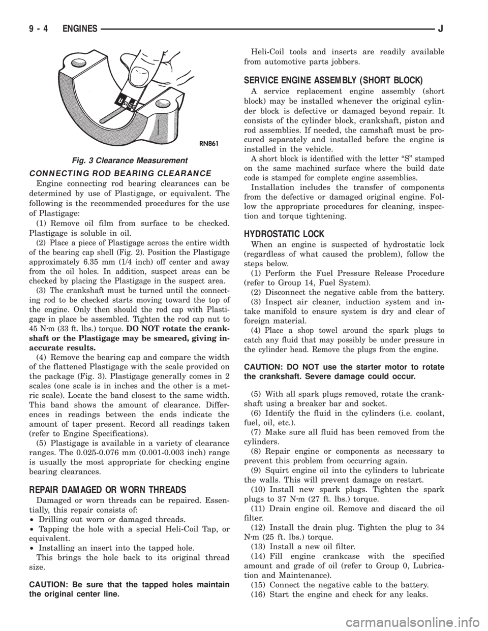
the package (Fig. 3). Plastigage generally comes in 2
scales (one scale is in inches and the other is a met-
ric scale). Locate the band closest to the same width.
This band shows the amount of clearance. Differ-
ences in readings between the ends indicate the
amount of taper present. Record all readings taken
(refer to Engine Specifications).
(5) Plastigage is available in a variety of clearance
ranges. The 0.025-0.076 mm (0.001-0.003 inch) range
is usually the most appropriate for checking engine
bearing clearances.
REPAIR DAMAGED OR WORN THREADS
Damaged or worn threads can be repaired. Essen-
tially, this repair consists of:
²Drilling out worn or damaged threads.
²Tapping the hole with a special Heli-Coil Tap, or
equivalent.
²Installing an insert into the tapped hole.
This brings the hole back to its original thread
size.
CAUTION: Be sure that the tapped holes maintain
the original center line.Heli-Coil tools and inserts are readily available
from automotive parts jobbers.
SERVICE ENGINE ASSEMBLY (SHORT BLOCK)
A service replacement engine assembly (short
block) may be installed whenever the original cylin-
der block is defective or damaged beyond repair. It
consists of the cylinder block, crankshaft, piston and
rod assemblies. If needed, the camshaft must be pro-
cured separately and installed before the engine is
installed in the vehicle.
A short block is identified with the letter ``S'' stamped
on the same machined surface where the build date
code is stamped for complete engine assemblies.
Installation includes the transfer of components
from the defective or damaged original engine. Fol-
low the appropriate procedures for cleaning, inspec-
tion and torque tightening.
HYDROSTATIC LOCK
When an engine is suspected of hydrostatic lock
(regardless of what caused the problem), follow the
steps below.
(1) Perform the Fuel Pressure Release Procedure
(refer to Group 14, Fuel System).
(2) Disconnect the negative cable from the battery.
(3) Inspect air cleaner, induction system and in-
take manifold to ensure system is dry and clear of
foreign material.
(4) Place a shop towel around the spark plugs to
catch any fluid that may possibly be under pressure in
the cylinder head. Remove the plugs from the engine.
CAUTION: DO NOT use the starter motor to rotate
the crankshaft. Severe damage could occur.
(5) With all spark plugs removed, rotate the crank-
shaft using a breaker bar and socket.
(6) Identify the fluid in the cylinders (i.e. coolant,
fuel, oil, etc.).
(7) Make sure all fluid has been removed from the
cylinders.
(8) Repair engine or components as necessary to
prevent this problem from occurring again.
(9) Squirt engine oil into the cylinders to lubricate
the walls. This will prevent damage on restart.
(10) Install new spark plugs. Tighten the spark
plugs to 37 Nzm (27 ft. lbs.) torque.
(11) Drain engine oil. Remove and discard the oil
filter.
(12) Install the drain plug. Tighten the plug to 34
Nzm (25 ft. lbs.) torque.
(13) Install a new oil filter.
(14) Fill engine crankcase with the specified
amount and grade of oil (refer to Group 0, Lubrica-
tion and Maintenance).
(15) Connect the negative cable to the battery.
(16) Start the engine and check for any leaks.
Fig. 3 Clearance Measurement
9 - 4 ENGINESJ
Page 1284 of 2158

ENGINE DIAGNOSIS
Engine diagnosis is helpful in determining the
causes of malfunctions not detected and remedied by
routine tune-ups.
These malfunctions may be classified as either per-
formance (e.g., engine idles rough and stalls) or me-
chanical (e.g., a strange noise).
Refer to the Service DiagnosisÐPerformance chart
and the Service DiagnosisÐMechanical chart for pos-
sible causes and corrections of malfunctions. Refer to
Group 14, Fuel System for the fuel system diagnosis.
GENERAL INFORMATION
Additional tests and diagnostic procedures may be
necessary for specific engine malfunctions that can
not be isolated with the Service Diagnosis charts. In-
formation concerning additional tests and diagnosis
is provided within the following diagnosis:
²Cylinder Compression Pressure Test.
²Cylinder Combustion Pressure Leakage Test.
²Engine Cylinder Head Gasket Failure Diagnosis.
²Intake Manifold Leakage Diagnosis.
INTAKE MANIFOLD LEAKAGE DIAGNOSIS
An intake manifold air leak is characterized by
lower than normal manifold vacuum. Also, one or
more cylinders may not be functioning.
WARNING: USE EXTREME CAUTION WHEN THE
ENGINE IS OPERATING. DO NOT STAND IN A DI-
RECT LINE WITH THE FAN. DO NOT PUT YOUR
HANDS NEAR THE PULLEYS, BELTS OR THE FAN.
DO NOT WEAR LOOSE CLOTHING.
METHOD 1
(1) Start the engine.
(2) Spray a small stream of water at the suspected
leak area.
(3) If a change in RPM'S, the area of the suspected
leak has been found.
(4) Repair as required.
CYLINDER COMPRESSION PRESSURE TEST
The results of a cylinder compression pressure test
can be utilized to diagnose several engine malfunc-
tions.
Ensure the battery is completely charged and the
engine starter motor is in good operating condition.
Otherwise the indicated compression pressures may
not be valid for diagnosis purposes.
(1) Clean the spark plug recesses with compressed
air.
(2) Remove the spark plugs.
(3) Secure the throttle in the wide-open position.
(4) Disconnect the ignition coil.(5) Insert a compression pressure gauge and rotate
the engine with the engine starter motor for three
revolutions.
(6) Record the compression pressure on the 3rd
revolution. Continue the test for the remaining cylin-
ders.
Refer to Engine Specifications for the correct en-
gine compression pressures.
ENGINE CYLINDER HEAD GASKET FAILURE
DIAGNOSIS
A leaking engine cylinder head gasket usually re-
sults in loss of power, loss of coolant and engine mis-
firing.
An engine cylinder head gasket leak can be located
between adjacent cylinders or between a cylinder and
the adjacent water jacket.
²An engine cylinder head gasket leaking between
adjacent cylinders is indicated by a loss of power
and/or engine misfire.
²An engine cylinder head gasket leaking between a
cylinder and an adjacent water jacket is indicated by
coolant foaming or overheating and loss of coolant.
CYLINDER-TO-CYLINDER LEAKAGE TEST
To determine if an engine cylinder head gasket is
leaking between adjacent cylinders; follow the proce-
dures outlined in Cylinder Compression Pressure
Test. An engine cylinder head gasket leaking between
adjacent cylinders will result in approximately a 50-
70% reduction in compression pressure.
CYLINDER-TO-WATER JACKET LEAKAGE
TEST
WARNING: USE EXTREME CAUTION WHEN THE
ENGINE IS OPERATING. DO NOT STAND IN A DI-
RECT LINE WITH THE FAN. DO NOT PUT YOUR
HANDS NEAR THE PULLEYS, BELTS OR THE FAN.
DO NOT WEAR LOOSE CLOTHING.
Remove the radiator cap.
Start the engine and allow it to warm up until the
engine thermostat opens.
If a large combustion/compression pressure leak ex-
ists, bubbles will be visible in the coolant.
If bubbles are not visible, install a radiator pres-
sure tester and pressurize the coolant system.
If a cylinder is leaking combustion pressure into
the water jacket, the tester pointer will pulsate with
every combustion stroke of the cylinder.
JENGINES 9 - 5
Page 1297 of 2158

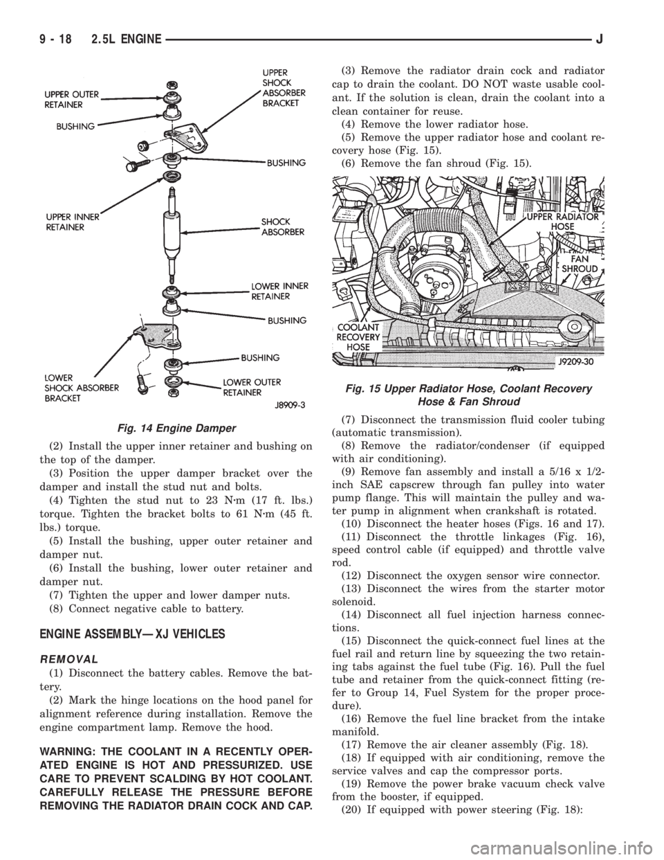
(2) Install the upper inner retainer and bushing on
the top of the damper.
(3) Position the upper damper bracket over the
damper and install the stud nut and bolts.
(4) Tighten the stud nut to 23 Nzm (17 ft. lbs.)
torque. Tighten the bracket bolts to 61 Nzm (45 ft.
lbs.) torque.
(5) Install the bushing, upper outer retainer and
damper nut.
(6) Install the bushing, lower outer retainer and
damper nut.
(7) Tighten the upper and lower damper nuts.
(8) Connect negative cable to battery.
ENGINE ASSEMBLYÐXJ VEHICLES
REMOVAL
(1) Disconnect the battery cables. Remove the bat-
tery.
(2) Mark the hinge locations on the hood panel for
alignment reference during installation. Remove the
engine compartment lamp. Remove the hood.
WARNING: THE COOLANT IN A RECENTLY OPER-
ATED ENGINE IS HOT AND PRESSURIZED. USE
CARE TO PREVENT SCALDING BY HOT COOLANT.
CAREFULLY RELEASE THE PRESSURE BEFORE
REMOVING THE RADIATOR DRAIN COCK AND CAP.(3) Remove the radiator drain cock and radiator
cap to drain the coolant. DO NOT waste usable cool-
ant. If the solution is clean, drain the coolant into a
clean container for reuse.
(4) Remove the lower radiator hose.
(5) Remove the upper radiator hose and coolant re-
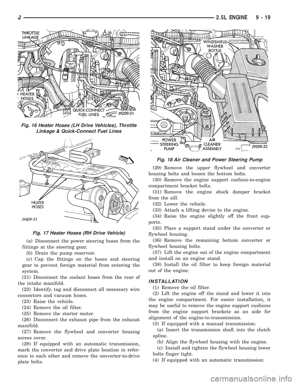
covery hose (Fig. 15).
(6) Remove the fan shroud (Fig. 15).
(7) Disconnect the transmission fluid cooler tubing
(automatic transmission).
(8) Remove the radiator/condenser (if equipped
with air conditioning).
(9) Remove fan assembly and install a 5/16 x 1/2-
inch SAE capscrew through fan pulley into water
pump flange. This will maintain the pulley and wa-
ter pump in alignment when crankshaft is rotated.
(10) Disconnect the heater hoses (Figs. 16 and 17).
(11) Disconnect the throttle linkages (Fig. 16),
speed control cable (if equipped) and throttle valve
rod.
(12) Disconnect the oxygen sensor wire connector.
(13) Disconnect the wires from the starter motor
solenoid.
(14) Disconnect all fuel injection harness connec-
tions.
(15) Disconnect the quick-connect fuel lines at the
fuel rail and return line by squeezing the two retain-
ing tabs against the fuel tube (Fig. 16). Pull the fuel
tube and retainer from the quick-connect fitting (re-
fer to Group 14, Fuel System for the proper proce-
dure).
(16) Remove the fuel line bracket from the intake
manifold.
(17) Remove the air cleaner assembly (Fig. 18).
(18) If equipped with air conditioning, remove the
service valves and cap the compressor ports.
(19) Remove the power brake vacuum check valve
from the booster, if equipped.
(20) If equipped with power steering (Fig. 18):
Fig. 14 Engine Damper
Fig. 15 Upper Radiator Hose, Coolant Recovery
Hose & Fan Shroud
9 - 18 2.5L ENGINEJ
Page 1298 of 2158

(a) Disconnect the power steering hoses from the
fittings at the steering gear.
(b) Drain the pump reservoir.
(c) Cap the fittings on the hoses and steering
gear to prevent foreign material from entering the
system.
(21) Disconnect the coolant hoses from the rear of
the intake manifold.
(22) Identify, tag and disconnect all necessary wire
connectors and vacuum hoses.
(23) Raise the vehicle.
(24) Remove the oil filter.
(25) Remove the starter motor.
(26) Disconnect the exhaust pipe from the exhaust
manifold.
(27) Remove the flywheel and converter housing
access cover.
(28) If equipped with an automatic transmission,
mark the converter and drive plate location in refer-
ence to each other and remove the converter-to-drive
plate bolts.(29) Remove the upper flywheel and converter
housing bolts and loosen the bottom bolts.
(30) Remove the engine support cushion-to-engine
compartment bracket bolts.
(31) Remove the engine shock damper bracket
from the sill.
(32) Lower the vehicle.
(33) Attach a lifting device to the engine.
(34) Raise the engine slightly off the front sup-
ports.
(35) Place a support stand under the converter or
flywheel housing.
(36) Remove the remaining bottom converter or
flywheel housing bolts.
(37) Lift the engine out of the engine compartment
and install on an engine stand.
(38) Install the oil filter to keep foreign material
out of the engine.
INSTALLATION
(1) Remove the oil filter.
(2) Lift the engine off the stand and lower it into
the engine compartment. For easier installation, it
may be useful to remove the engine support cushions
from the engine support brackets as an aide for
alignment of the engine-to-transmission.
(3) If equipped with a manual transmission:
(a) Insert the transmission shaft into the clutch
spline.
(b) Align the flywheel housing with the engine.
(c) Install and tighten the flywheel housing lower
bolts finger tight.
(4) If equipped with an automatic transmission:
Fig. 16 Heater Hoses (LH Drive Vehicles), Throttle
Linkage & Quick-Connect Fuel Lines
Fig. 17 Heater Hoses (RH Drive Vehicle)
Fig. 18 Air Cleaner and Power Steering Pump
J2.5L ENGINE 9 - 19