1995 JEEP YJ boot
[x] Cancel search: bootPage 216 of 2158
(8) Remove shift handle by pulling upward sharply
on handle. Then remove shift bezel (Fig. 7).
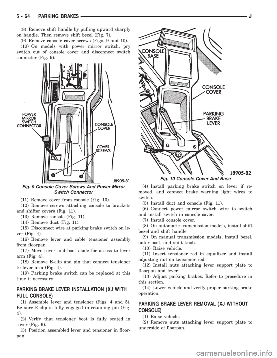
(9) Remove console cover screws (Figs. 9 and 10).
(10) On models with power mirror switch, pry
switch out of console cover and disconnect switch
connector (Fig. 9).
(11) Remove cover from console (Fig. 10).
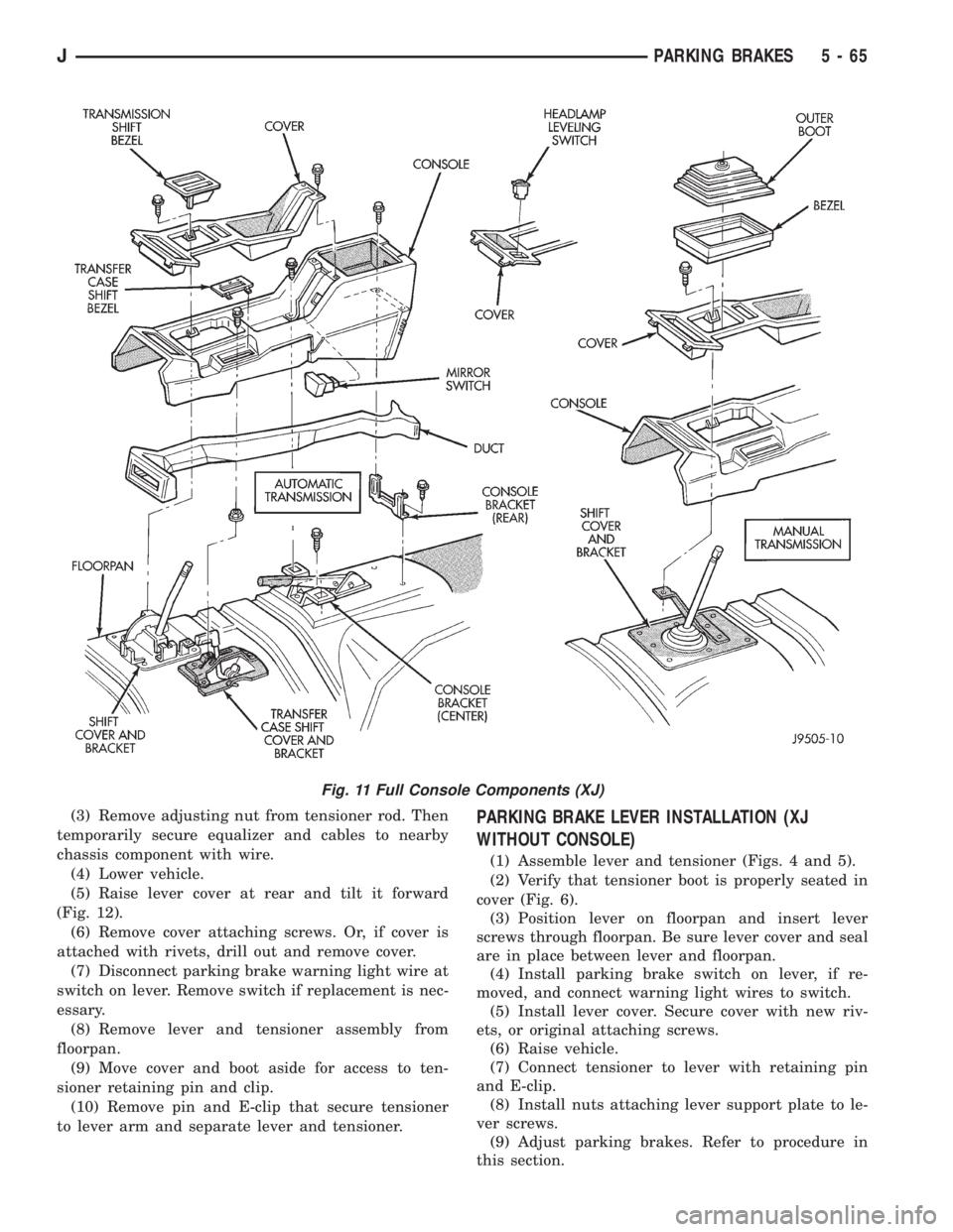
(12) Remove screws attaching console to brackets
and shifter covers (Fig. 11).
(13) Remove console (Fig. 11).
(14) Remove duct (Fig. 11).
(15) Disconnect wire at parking brake switch on le-
ver (Fig. 4).
(16) Remove lever and cable tensioner assembly
from floorpan.
(17) Move cover and boot aside for access to lever
arm (Fig. 4).
(18) Remove E-clip and pin that connect tensioner
to lever arm (Fig. 4).
(19) Parking brake switch can be replaced at this
time if necessary.
PARKING BRAKE LEVER INSTALLATION (XJ WITH
FULL CONSOLE)
(1) Assemble lever and tensioner (Figs. 4 and 5).
Be sure E-clip is fully engaged in retaining pin (Fig.
4).
(2) Verify that tensioner boot is fully seated in
cover (Fig. 6).
(3) Position assembled lever and tensioner in floor-
pan.(4) Install parking brake switch on lever if re-
moved, and connect brake warning light wires to
switch.
(5) Install duct and console (Fig. 11).
(6) Connect power mirror switch wire to switch
and install switch in console cover.
(7) Install console cover.
(8) On automatic transmission models, install shift
bezel and shift handle.
(9) On manual transmission models, install bezel,
outer boot, and shift knob.
(10) Raise vehicle.
(11) Insert tensioner rod in equalizer and install
adjusting nut on tensioner rod.
(12) Install nuts attaching lever support plate to
floorpan and lever.
(13) Adjust parking brakes. Refer to procedure in
this section.
(14) Lower vehicle and verify proper parking brake
operation.PARKING BRAKE LEVER REMOVAL (XJ WITHOUT
CONSOLE)
(1) Raise vehicle.
(2) Remove nuts attaching lever support plate to
underside of floorpan.
Fig. 9 Console Cover Screws And Power Mirror
Switch Connector
Fig. 10 Console Cover And Base
5 - 64 PARKING BRAKESJ
Page 217 of 2158
(3) Remove adjusting nut from tensioner rod. Then
temporarily secure equalizer and cables to nearby
chassis component with wire.
(4) Lower vehicle.
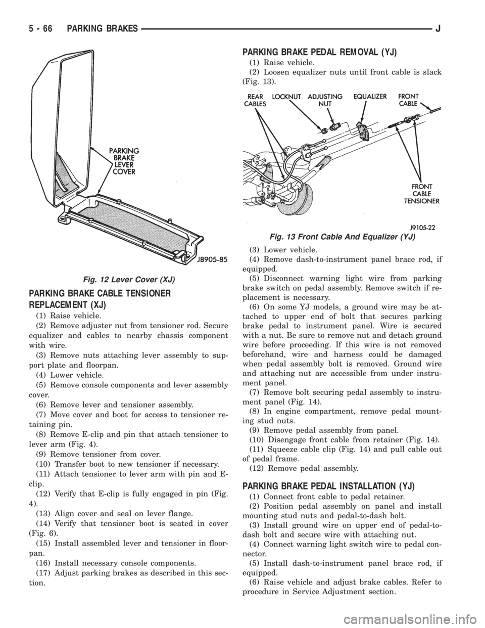
(5) Raise lever cover at rear and tilt it forward
(Fig. 12).
(6) Remove cover attaching screws. Or, if cover is
attached with rivets, drill out and remove cover.
(7) Disconnect parking brake warning light wire at
switch on lever. Remove switch if replacement is nec-
essary.
(8) Remove lever and tensioner assembly from
floorpan.
(9) Move cover and boot aside for access to ten-
sioner retaining pin and clip.
(10) Remove pin and E-clip that secure tensioner
to lever arm and separate lever and tensioner.PARKING BRAKE LEVER INSTALLATION (XJ
WITHOUT CONSOLE)
(1) Assemble lever and tensioner (Figs. 4 and 5).
(2) Verify that tensioner boot is properly seated in
cover (Fig. 6).
(3) Position lever on floorpan and insert lever
screws through floorpan. Be sure lever cover and seal
are in place between lever and floorpan.
(4) Install parking brake switch on lever, if re-
moved, and connect warning light wires to switch.
(5) Install lever cover. Secure cover with new riv-
ets, or original attaching screws.
(6) Raise vehicle.
(7) Connect tensioner to lever with retaining pin
and E-clip.
(8) Install nuts attaching lever support plate to le-
ver screws.
(9) Adjust parking brakes. Refer to procedure in
this section.
Fig. 11 Full Console Components (XJ)
JPARKING BRAKES 5 - 65
Page 218 of 2158
PARKING BRAKE CABLE TENSIONER
REPLACEMENT (XJ)
(1) Raise vehicle.
(2) Remove adjuster nut from tensioner rod. Secure
equalizer and cables to nearby chassis component
with wire.
(3) Remove nuts attaching lever assembly to sup-
port plate and floorpan.
(4) Lower vehicle.
(5) Remove console components and lever assembly
cover.
(6) Remove lever and tensioner assembly.
(7) Move cover and boot for access to tensioner re-
taining pin.
(8) Remove E-clip and pin that attach tensioner to
lever arm (Fig. 4).
(9) Remove tensioner from cover.
(10) Transfer boot to new tensioner if necessary.
(11) Attach tensioner to lever arm with pin and E-
clip.
(12) Verify that E-clip is fully engaged in pin (Fig.
4).
(13) Align cover and seal on lever flange.
(14) Verify that tensioner boot is seated in cover
(Fig. 6).
(15) Install assembled lever and tensioner in floor-
pan.
(16) Install necessary console components.
(17) Adjust parking brakes as described in this sec-
tion.
PARKING BRAKE PEDAL REMOVAL (YJ)
(1) Raise vehicle.
(2) Loosen equalizer nuts until front cable is slack
(Fig. 13).
(3) Lower vehicle.
(4) Remove dash-to-instrument panel brace rod, if
equipped.
(5) Disconnect warning light wire from parking
brake switch on pedal assembly. Remove switch if re-
placement is necessary.
(6) On some YJ models, a ground wire may be at-
tached to upper end of bolt that secures parking
brake pedal to instrument panel. Wire is secured
with a nut. Be sure to remove nut and detach ground
wire before proceeding. If this wire is not removed
beforehand, wire and harness could be damaged
when pedal assembly bolt is removed. Ground wire
and attaching nut are accessible from under instru-
ment panel.
(7) Remove bolt securing pedal assembly to instru-
ment panel (Fig. 14).
(8) In engine compartment, remove pedal mount-
ing stud nuts.
(9) Remove pedal assembly from panel.
(10) Disengage front cable from retainer (Fig. 14).
(11) Squeeze cable clip (Fig. 14) and pull cable out
of pedal frame.
(12) Remove pedal assembly.
PARKING BRAKE PEDAL INSTALLATION (YJ)
(1) Connect front cable to pedal retainer.
(2) Position pedal assembly on panel and install
mounting stud nuts and pedal-to-dash bolt.
(3) Install ground wire on upper end of pedal-to-
dash bolt and secure wire with attaching nut.
(4) Connect warning light switch wire to pedal con-
nector.
(5) Install dash-to-instrument panel brace rod, if
equipped.
(6) Raise vehicle and adjust brake cables. Refer to
procedure in Service Adjustment section.
Fig. 12 Lever Cover (XJ)
Fig. 13 Front Cable And Equalizer (YJ)
5 - 66 PARKING BRAKESJ
Page 334 of 2158

IGNITION SECONDARY CIRCUIT DIAGNOSIS
CHECKING FOR SPARK
CAUTION: When disconnecting a high voltage cable
from a spark plug or from the distributor cap, twist
the rubber boot slightly (1/2 turn) to break it loose
(Fig. 12). Grasp the boot (not the cable) and pull it
off with a steady, even force.
(1) Disconnect the ignition coil secondary cable
from center tower of the distributor cap. Hold the ca-
ble terminal approximately 12 mm (1/2 in.) from a
good engine ground (Fig. 13).
WARNING: BE VERY CAREFUL WHEN THE ENGINE
IS CRANKING. DO NOT PUT YOUR HANDS NEAR
THE PULLEYS, BELTS OR THE FAN. DO NOT WEAR
LOOSE FITTING CLOTHING.
(2) Rotate (crank) the engine with the starter mo-
tor and observe the cable terminal for a steady arc. If
steady arcing does not occur, inspect the secondary
coil cable. Refer to Spark Plug Cables in this group.
Also inspect the distributor cap and rotor for cracksor burn marks. Repair as necessary. If steady arcing
occurs, connect ignition coil cable to the distributor
cap.
(3) Remove a cable from one spark plug.
(4) Using insulated pliers, hold the cable terminal
approximately 12 mm (1/2 in.) from the engine cylin-
der head or block while rotating the engine with the
starter motor. Observe the spark plug cable terminal
for an arc. If steady arcing occurs, it can be expected
that the ignition secondary system is operating cor-
rectly.(note that if the ignition coil cable is re-
moved for this test, instead of a spark plug
cable, the spark intensity will be much higher.)
If steady arcing occurs at the spark plug cables, but
the engine will not start, connect the DRB scan tool.
Refer to the Powertrain Diagnostic Procedures ser-
vice manual.
FAILURE TO START TEST
To prevent unnecessary diagnostic time and wrong
test results, the previous Checking For Spark test
should be performed prior to this test.
WARNING: SET PARKING BRAKE OR BLOCK THE
DRIVE WHEELS BEFORE PROCEEDING WITH THIS
TEST.
(1) Unplug the ignition coil harness connector at
the coil (Fig. 14).
(2) Connect a set of small jumper wires (18 gauge
or smaller) between the disconnected harness termi-
nals and the ignition coil terminals. To determine po-
larity at connector and coil, refer to the Wiring
Diagrams section.
(3) Attach one lead of a voltmeter to the positive
(12 volt) jumper wire. Attach the negative side of
voltmeter to a good ground. Determine that sufficient
battery voltage (12.4 volts) is present for the starting
and ignition systems.
Fig. 12 Cable Removal
Fig. 13 Checking for SparkÐTypical
Fig. 14 Coil Harness ConnectorÐTypical (4.0L
Shown)
8D - 10 IGNITION SYSTEMSJ
Page 338 of 2158

temperature ranges. This depends upon the thick-
ness and length of the center electrodes porcelain in-
sulator.)
SPARK PLUG OVERHEATING
Overheating is indicated by a white or gray center
electrode insulator that also appears blistered (Fig.
25). The increase in electrode gap will be consider-
ably in excess of 0.001 inch per 1000 miles of opera-
tion. This suggests that a plug with a cooler heat
range rating should be used. Over advanced ignition
timing, detonation and cooling system malfunctions
can also cause spark plug overheating.
SPARK PLUG SECONDARY CABLES
TESTING
Spark plug cables are sometimes referred to as sec-
ondary ignition cables or secondary wires. The cables
transfer electrical current from the distributor to in-
dividual spark plugs at each cylinder. The spark plug
cables are of nonmetallic construction and have a
built in resistance. The cables provide suppression of
radio frequency emissions from the ignition system.Check the high-tension cable connections for good
contact at the ignition coil, distributor cap towers
and spark plugs. Terminals should be fully seated.
The terminals and spark plug covers should be in
good condition. Terminals should fit tightly to the ig-
nition coil, distributor cap and spark plugs. The
spark plug cover (boot) of the cable should fit tight
around the spark plug insulator. Loose cable connec-
tions can cause corrosion and increase resistance, re-
sulting in shorter cable service life.
Clean the high tension cables with a cloth moist-
ened with a nonflammable solvent and wipe dry.
Check for brittle or cracked insulation.
When testing secondary cables for damage with an
oscilloscope, follow the instructions of the equipment
manufacturer.
If an oscilloscope is not available, spark plug cables
may be tested as follows:
CAUTION: Do not leave any one spark plug cable
disconnected for longer than necessary during test-
ing. This may cause possible heat damage to the
catalytic converter. Total test time must not exceed
ten minutes.
With the engine not running, connect one end of a
test probe to a good ground. Start the engine and run
the other end of the test probe along the entire
length of all spark plug cables. If cables are cracked
or punctured, there will be a noticeable spark jump
from the damaged area to the test probe. The cable
running from the ignition coil to the distributor cap
can be checked in the same manner. Cracked, dam-
aged or faulty cables should be replaced with resis-
tance type cable. This can be identified by the words
ELECTRONIC SUPPRESSION printed on the cable
jacket.
Use an ohmmeter to test for open circuits, exces-
sive resistance or loose terminals. Remove the dis-
tributor cap from the distributor.Do not remove
cables from cap.Remove cable from spark plug.
Connect ohmmeter to spark plug terminal end of ca-
ble and to corresponding electrode in distributor cap.
Resistance should be 250 to 1000 Ohms per inch of
cable. If not, remove cable from distributor cap tower
and connect ohmmeter to the terminal ends of cable.
If resistance is not within specifications as found in
the Spark Plug Cable Resistance chart, replace the
cable. Test all spark plug cables in this manner.
Fig. 24 Preignition Damage
Fig. 25 Spark Plug Overheating
SPARK PLUG CABLE RESISTANCE
8D - 14 IGNITION SYSTEMSJ
Page 347 of 2158

(3) Remove ignition coil mounting bolts (nuts are
used on back side of bracket). Remove coil.
INSTALLATION
(1) Install ignition coil to bracket on cylinder block
with mounting bolts and nuts.
(2) Connect engine harness connector to coil.
(3) Connect ignition coil cable to ignition coil.
INTAKE MANIFOLD AIR TEMPERATURE SENSOR
For an operational description, diagnosis or remov-
al/ installation procedures, refer to Group 14, Fuel
Systems.
MANIFOLD ABSOLUTE PRESSURE (MAP) SENSOR
For an operational description, diagnosis and re-
moval/installation procedures, refer to Group 14,
Fuel System.
OXYGEN (O2S) SENSOR
For an operational description, diagnosis or remov-
al/ installation procedures, refer to Group 14, Fuel
Systems.
POWERTRAIN CONTROL MODULE (PCM)
The PCM was formerly referred to as the SBEC or
engine controller.
XJ MODELS
On XJ models, the PCM is located in the engine
compartment next to the air cleaner (Fig. 17).
REMOVAL
(1) Disconnect negative battery cable at battery.
(2) Loosen 60-way connector mounting screw until
connector can be disengaged from PCM.
(3) Pull 60-way connector straight back from PCM.
(4) Remove PCM mounting bolts.
(5) Remove PCM from vehicle.INSTALLATION
(1) Check the pins in the PCM 60-way electrical
connector for damage. Repair as necessary.
(2) Install PCM. Tighten mounting bolts to 1 Nzm
(9 in. lbs.) torque.
(3) Engage 60-way connector into PCM. Tighten
connector mounting screw to 4 Nzm (35 in. lbs.)
torque.
(4) Connect battery cable to battery.
YJ MODELS
On YJ models, the PCM is located in the engine
compartment behind the windshield washer fluid res-
ervoir (Fig. 18).
REMOVAL
(1) Disconnect negative battery cable at battery.
(2) Remove windshield washer fluid reservoir.
(3) Loosen 60-way connector mounting screw until
connector can be disengaged from PCM.
(4) Pull 60-way connector straight back from PCM.
(5) Remove PCM mounting bolts.
(6) Remove PCM from vehicle.
INSTALLATION
(1) Check the pins in the PCM 60-way electrical
connector for damage. Repair as necessary.
(2) Install PCM. Tighten mounting bolts to 1 Nzm
(9 in. lbs.) torque.
(3) Engage 60-way connector into PCM. Tighten
connector mounting screw to 4 Nzm (35 in. lbs.)
torque.
(4) Connect battery cable to battery.
(5) Install washer fluid reservoir.
SPARK PLUGS
PLUG REMOVAL
(1) Always remove spark plug or ignition coil ca-
bles by grasping at the cable boot (Fig. 19). Turn the
cable boot 1/2 turn and pull straight back in a steady
Fig. 17 PCM LocationÐXJ Models
Fig. 18 PCM LocationÐYJ Models
JIGNITION SYSTEMS 8D - 23
Page 348 of 2158
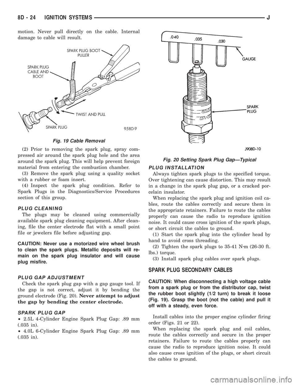
motion. Never pull directly on the cable. Internal
damage to cable will result.
(2) Prior to removing the spark plug, spray com-
pressed air around the spark plug hole and the area
around the spark plug. This will help prevent foreign
material from entering the combustion chamber.
(3) Remove the spark plug using a quality socket
with a rubber or foam insert.
(4) Inspect the spark plug condition. Refer to
Spark Plugs in the Diagnostics/Service Procedures
section of this group.
PLUG CLEANING
The plugs may be cleaned using commercially
available spark plug cleaning equipment. After clean-
ing, file the center electrode flat with a small point
file or jewelers file before adjusting gap.
CAUTION: Never use a motorized wire wheel brush
to clean the spark plugs. Metallic deposits will re-
main on the spark plug insulator and will cause
plug misfire.
PLUG GAP ADJUSTMENT
Check the spark plug gap with a gap gauge tool. If
the gap is not correct, adjust it by bending the
ground electrode (Fig. 20).Never attempt to adjust
the gap by bending the center electrode.
SPARK PLUG GAP
²2.5L 4-Cylinder Engine Spark Plug Gap: .89 mm
(.035 in).
²4.0L 6-Cylinder Engine Spark Plug Gap: .89 mm
(.035 in).
PLUG INSTALLATION
Always tighten spark plugs to the specified torque.
Over tightening can cause distortion. This may result
in a change in the spark plug gap, or a cracked por-
celain insulator.
When replacing the spark plug and ignition coil ca-
bles, route the cables correctly and secure them in
the appropriate retainers. Failure to route the cables
properly can cause the radio to reproduce ignition
noise. It could cause cross ignition of the spark plugs,
or short circuit the cables to ground.
(1) Start the spark plug into the cylinder head by
hand to avoid cross threading.
(2) Tighten the spark plugs to 35-41 Nzm (26-30 ft.
lbs.) torque.
(3) Install spark plug cables over spark plugs.
SPARK PLUG SECONDARY CABLES
CAUTION: When disconnecting a high voltage cable
from a spark plug or from the distributor cap, twist
the rubber boot slightly (1/2 turn) to break it loose
(Fig. 19). Grasp the boot (not the cable) and pull it
off with a steady, even force.
Install cables into the proper engine cylinder firing
order (Figs. 21 or 22).
When replacing the spark plug and coil cables,
route the cables correctly and secure in the proper
retainers. Failure to route the cables properly can
cause the radio to reproduce ignition noise. It could
also cause cross ignition of the plugs, or short circuit
the cables to ground.
Fig. 19 Cable Removal
Fig. 20 Setting Spark Plug GapÐTypical
8D - 24 IGNITION SYSTEMSJ
Page 440 of 2158
SERVICE PROCEDURES - XJ
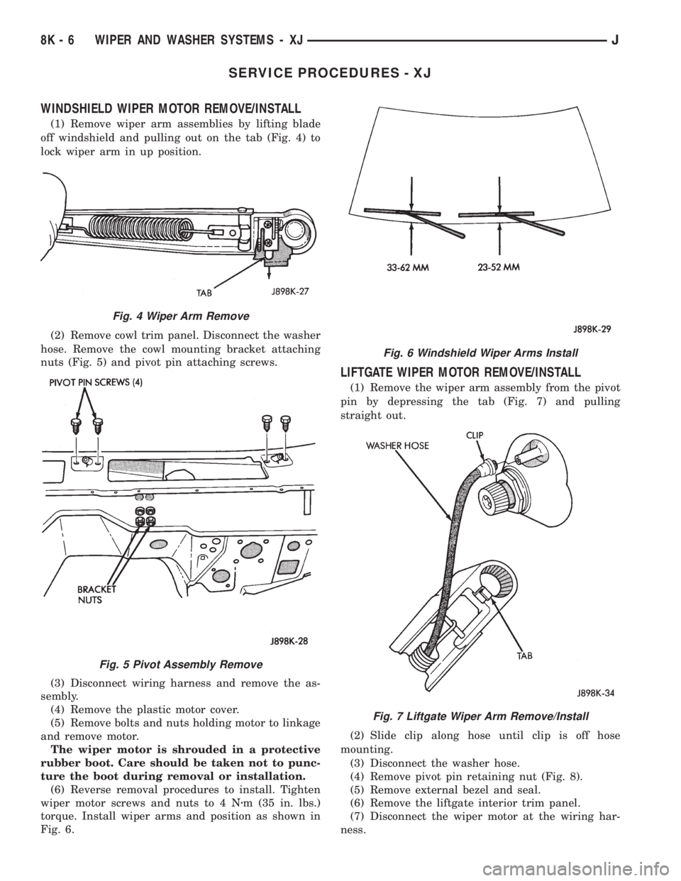
WINDSHIELD WIPER MOTOR REMOVE/INSTALL
(1) Remove wiper arm assemblies by lifting blade
off windshield and pulling out on the tab (Fig. 4) to
lock wiper arm in up position.
(2) Remove cowl trim panel. Disconnect the washer
hose. Remove the cowl mounting bracket attaching
nuts (Fig. 5) and pivot pin attaching screws.
(3) Disconnect wiring harness and remove the as-
sembly.
(4) Remove the plastic motor cover.
(5) Remove bolts and nuts holding motor to linkage
and remove motor.
The wiper motor is shrouded in a protective
rubber boot. Care should be taken not to punc-
ture the boot during removal or installation.
(6) Reverse removal procedures to install. Tighten
wiper motor screws and nuts to 4 Nzm (35 in. lbs.)
torque. Install wiper arms and position as shown in
Fig. 6.
LIFTGATE WIPER MOTOR REMOVE/INSTALL
(1) Remove the wiper arm assembly from the pivot
pin by depressing the tab (Fig. 7) and pulling
straight out.
(2) Slide clip along hose until clip is off hose
mounting.
(3) Disconnect the washer hose.
(4) Remove pivot pin retaining nut (Fig. 8).
(5) Remove external bezel and seal.
(6) Remove the liftgate interior trim panel.
(7) Disconnect the wiper motor at the wiring har-
ness.
Fig. 4 Wiper Arm Remove
Fig. 5 Pivot Assembly Remove
Fig. 6 Windshield Wiper Arms Install
Fig. 7 Liftgate Wiper Arm Remove/Install
8K - 6 WIPER AND WASHER SYSTEMS - XJJ