1995 JEEP YJ transmission fluid
[x] Cancel search: transmission fluidPage 1862 of 2158
MAINSHAFT ASSEMBLY
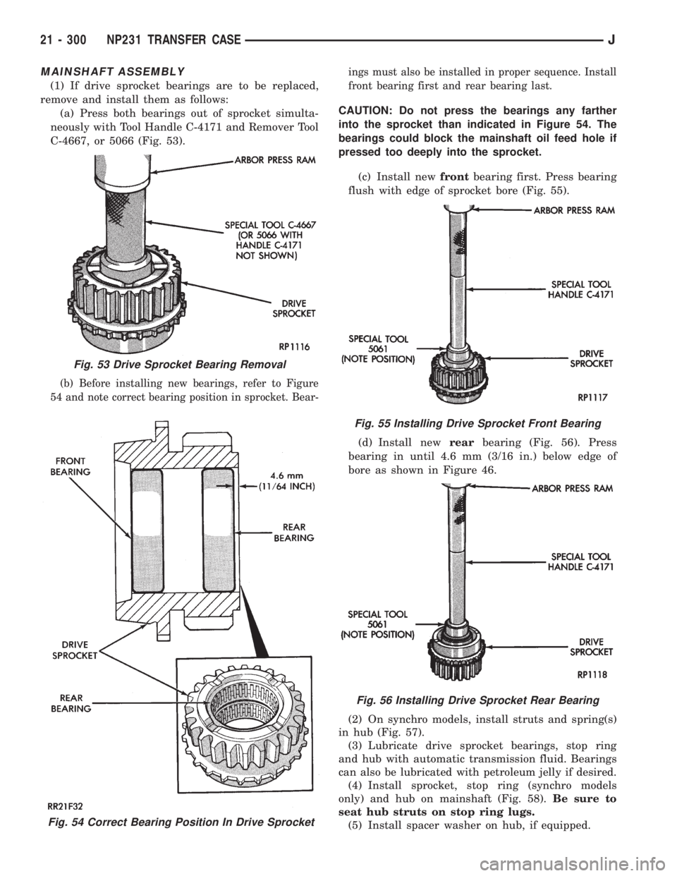
(1) If drive sprocket bearings are to be replaced,
remove and install them as follows:
(a) Press both bearings out of sprocket simulta-
neously with Tool Handle C-4171 and Remover Tool
C-4667, or 5066 (Fig. 53).
(b) Before installing new bearings, refer to Figure
54 and note correct bearing position in sprocket. Bear-ings must also be installed in proper sequence. Install
front bearing first and rear bearing last.
CAUTION: Do not press the bearings any farther
into the sprocket than indicated in Figure 54. The
bearings could block the mainshaft oil feed hole if
pressed too deeply into the sprocket.
(c) Install newfrontbearing first. Press bearing
flush with edge of sprocket bore (Fig. 55).
(d) Install newrearbearing (Fig. 56). Press
bearing in until 4.6 mm (3/16 in.) below edge of
bore as shown in Figure 46.
(2) On synchro models, install struts and spring(s)
in hub (Fig. 57).
(3) Lubricate drive sprocket bearings, stop ring
and hub with automatic transmission fluid. Bearings
can also be lubricated with petroleum jelly if desired.
(4) Install sprocket, stop ring (synchro models
only) and hub on mainshaft (Fig. 58).Be sure to
seat hub struts on stop ring lugs.
(5) Install spacer washer on hub, if equipped.
Fig. 54 Correct Bearing Position In Drive Sprocket
Fig. 53 Drive Sprocket Bearing Removal
Fig. 55 Installing Drive Sprocket Front Bearing
Fig. 56 Installing Drive Sprocket Rear Bearing
21 - 300 NP231 TRANSFER CASEJ
Page 1864 of 2158
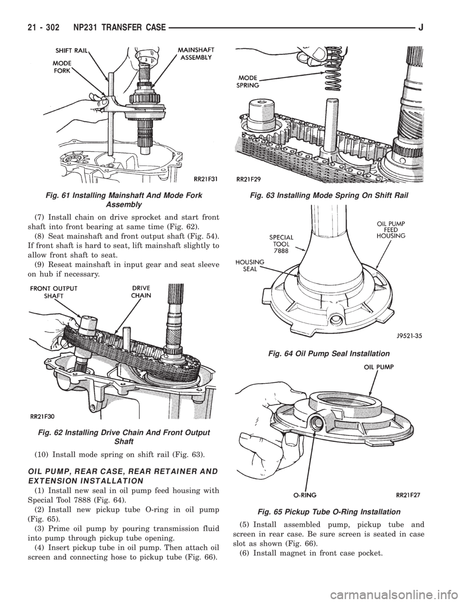
(7) Install chain on drive sprocket and start front
shaft into front bearing at same time (Fig. 62).
(8) Seat mainshaft and front output shaft (Fig. 54).
If front shaft is hard to seat, lift mainshaft slightly to
allow front shaft to seat.
(9) Reseat mainshaft in input gear and seat sleeve
on hub if necessary.
(10) Install mode spring on shift rail (Fig. 63).
OIL PUMP, REAR CASE, REAR RETAINER AND
EXTENSION INSTALLATION
(1) Install new seal in oil pump feed housing with
Special Tool 7888 (Fig. 64).
(2) Install new pickup tube O-ring in oil pump
(Fig. 65).
(3) Prime oil pump by pouring transmission fluid
into pump through pickup tube opening.
(4) Insert pickup tube in oil pump. Then attach oil
screen and connecting hose to pickup tube (Fig. 66).(5) Install assembled pump, pickup tube and
screen in rear case. Be sure screen is seated in case
slot as shown (Fig. 66).
(6) Install magnet in front case pocket.
Fig. 61 Installing Mainshaft And Mode Fork
Assembly
Fig. 62 Installing Drive Chain And Front Output
Shaft
Fig. 63 Installing Mode Spring On Shift Rail
Fig. 64 Oil Pump Seal Installation
Fig. 65 Pickup Tube O-Ring Installation
21 - 302 NP231 TRANSFER CASEJ
Page 1881 of 2158
Inspect the differential gears, thrust washers and
case halves. Replace the mainshaft gear if the gear
teeth or the brass ring on the underside of the gear
are damaged. Replace the differential as an assembly
if the gears, case halves, or the pins in the lower case
half are damaged.
Inspect the case halves, extension housing and re-
tainers for cracks, porosity, or damaged sealing sur-
faces. Inspect the shafts, gears, chain and shift
components for wear or damage.
Inspect all of the transfer case bearings for wear,
roughness, pitting, or galling. Replace worn or dam-
aged bearings as outlined in the assembly section.
TRANSFER CASE ASSEMBLY
(1) Lubricate transfer case components with auto-
matic transmission fluid or petroleum jelly (where in-
dicated) during assembly.
CAUTION: The bearing bores in various transfer
case components contain oil feed holes. Be sure re-
placement bearings do not block these feed holes.
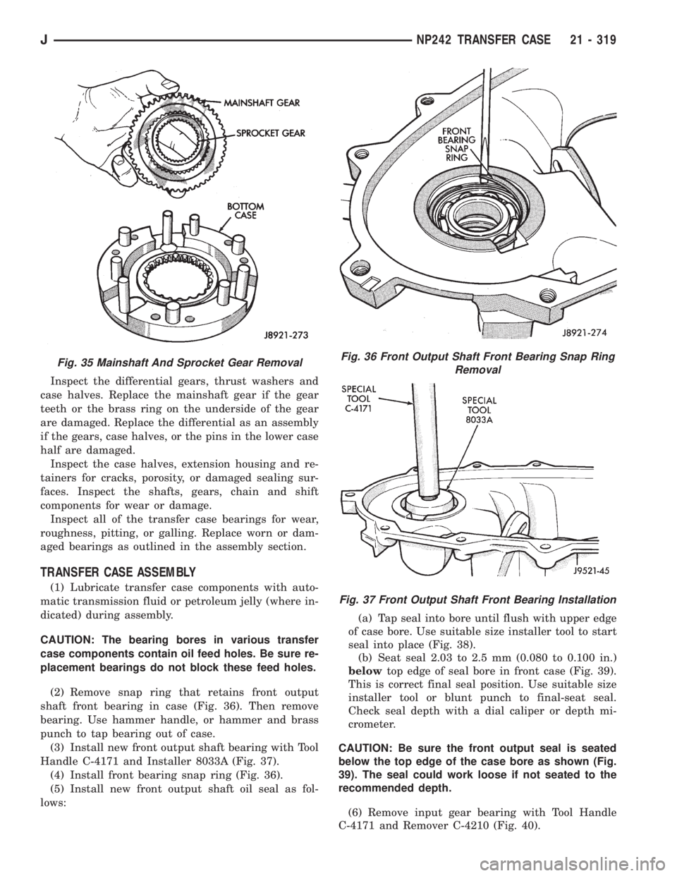
(2) Remove snap ring that retains front output
shaft front bearing in case (Fig. 36). Then remove
bearing. Use hammer handle, or hammer and brass
punch to tap bearing out of case.
(3) Install new front output shaft bearing with Tool
Handle C-4171 and Installer 8033A (Fig. 37).
(4) Install front bearing snap ring (Fig. 36).
(5) Install new front output shaft oil seal as fol-
lows:(a) Tap seal into bore until flush with upper edge
of case bore. Use suitable size installer tool to start
seal into place (Fig. 38).
(b) Seat seal 2.03 to 2.5 mm (0.080 to 0.100 in.)
belowtop edge of seal bore in front case (Fig. 39).
This is correct final seal position. Use suitable size
installer tool or blunt punch to final-seat seal.
Check seal depth with a dial caliper or depth mi-
crometer.
CAUTION: Be sure the front output seal is seated
below the top edge of the case bore as shown (Fig.
39). The seal could work loose if not seated to the
recommended depth.
(6) Remove input gear bearing with Tool Handle
C-4171 and Remover C-4210 (Fig. 40).
Fig. 35 Mainshaft And Sprocket Gear RemovalFig. 36 Front Output Shaft Front Bearing Snap Ring
Removal
Fig. 37 Front Output Shaft Front Bearing Installation
JNP242 TRANSFER CASE 21 - 319
Page 1883 of 2158
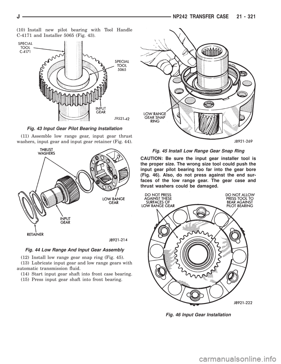
(10) Install new pilot bearing with Tool Handle
C-4171 and Installer 5065 (Fig. 43).
(11) Assemble low range gear, input gear thrust
washers, input gear and input gear retainer (Fig. 44).
(12) Install low range gear snap ring (Fig. 45).
(13) Lubricate input gear and low range gears with
automatic transmission fluid.
(14) Start input gear shaft into front case bearing.
(15) Press input gear shaft into front bearing.CAUTION: Be sure the input gear installer tool is
the proper size. The wrong size tool could push the
input gear pilot bearing too far into the gear bore
(Fig. 46). Also, do not press against the end sur-
faces of the low range gear. The gear case and
thrust washers could be damaged.
Fig. 43 Input Gear Pilot Bearing Installation
Fig. 44 Low Range And Input Gear Assembly
Fig. 45 Install Low Range Gear Snap Ring
Fig. 46 Input Gear Installation
JNP242 TRANSFER CASE 21 - 321
Page 1885 of 2158
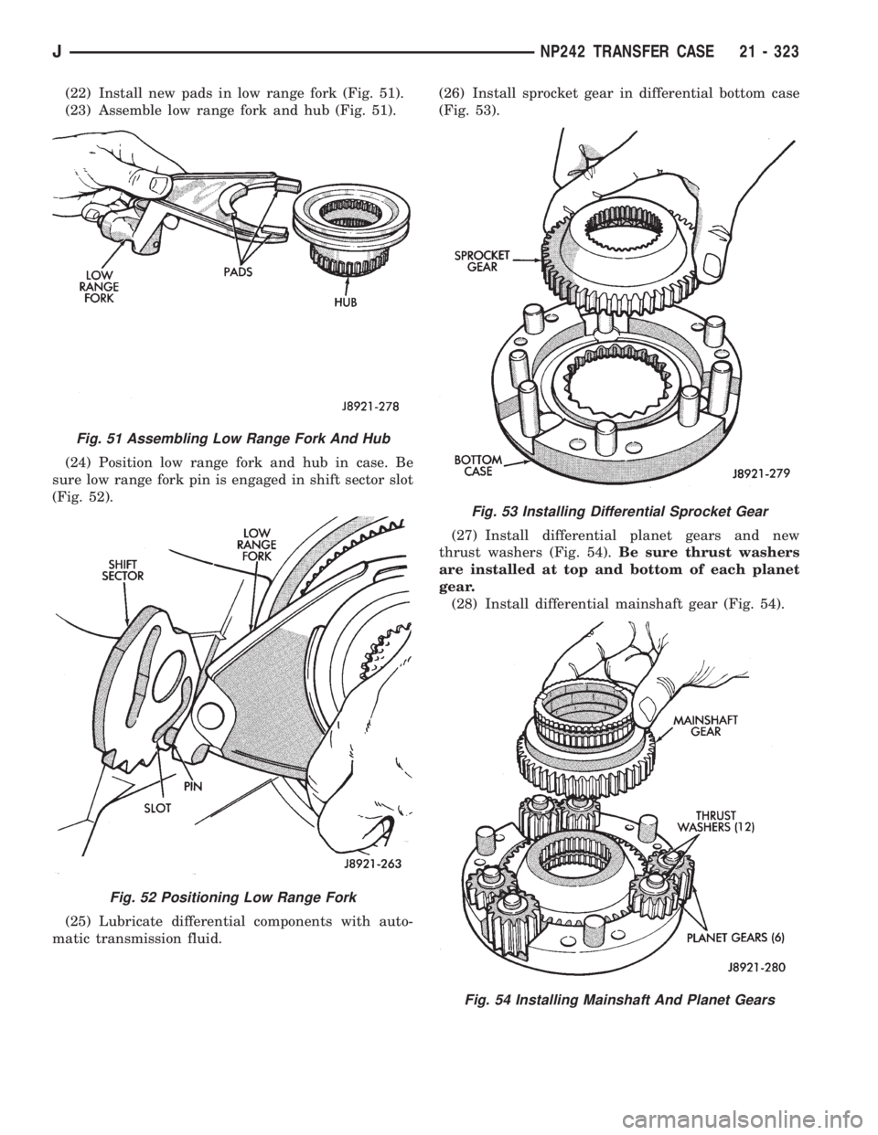
(22) Install new pads in low range fork (Fig. 51).
(23) Assemble low range fork and hub (Fig. 51).
(24) Position low range fork and hub in case. Be
sure low range fork pin is engaged in shift sector slot
(Fig. 52).
(25) Lubricate differential components with auto-
matic transmission fluid.(26) Install sprocket gear in differential bottom case
(Fig. 53).
(27) Install differential planet gears and new
thrust washers (Fig. 54).Be sure thrust washers
are installed at top and bottom of each planet
gear.
(28) Install differential mainshaft gear (Fig. 54).
Fig. 51 Assembling Low Range Fork And Hub
Fig. 52 Positioning Low Range Fork
Fig. 53 Installing Differential Sprocket Gear
Fig. 54 Installing Mainshaft And Planet Gears
JNP242 TRANSFER CASE 21 - 323
Page 1995 of 2158
TRAILER HITCH
TRAILER HITCHÐXJ
CLASS III HITCH
A class III weight-distributing/equalizer type hitch
can be used to tow a trailer:
²Having a maximum gross weight of 5,000 lbs/2250
kg.
²Having a maximum tongue weight of 750 lbs/332
kg).
The following vehicle basic equipment is required
for class III trailer towing:
²P205/75R15 or larger tires.
²Full size spare tire.
²Trailer sway control.
²Trailer tow wire harness and connector.
²Heavy duty turn signal flasher element.
²Heavy duty axle (with synthetic lubricant).
²Heavy duty cooling system.
²Heavy duty generator/battery.
²Auxiliary automatic transmission fluid cooler.
²I-6, 4.0L engine.
Wide-angle type door mirrors are recommended but
not required.
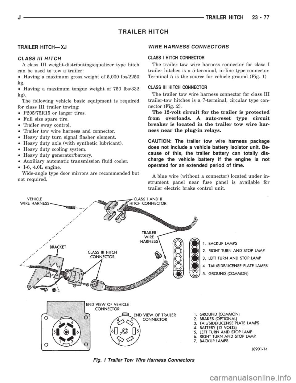
WIRE HARNESS CONNECTORS
CLASS I HITCH CONNECTOR
The trailer tow wire harness connector for class I
trailer hitches is a 5-terminal, in-line type connector.
Terminal 5 is the source for vehicle ground (Fig. 1)
CLASS III HITCH CONNECTOR
The trailer tow wire harness connector for class III
trailer-tow hitches is a 7-terminal, circular type con-
nector (Fig. 2).
The 12-volt circuit for the trailer is protected
from overloads. A auto-reset type circuit
breaker is located in the trailer tow wire har-
ness near the plug-in relays.
CAUTION: The trailer tow wire harness package
does not include a vehicle battery isolator unit. Be-
cause of this, the trailer battery can totally dis-
charge the vehicle battery if the engine is not
operated for an extended period of time.
A blue wire (without a connector) located under in-
strument panel near fuse panel is available for
trailer electric brake control unit.
Fig. 1 Trailer Tow Wire Harness Connectors
JTRAILER HITCH 23 - 77
Page 2107 of 2158
A/C RECIRCULATING DOOR VACUUM MOTOR
REPLACEMENT
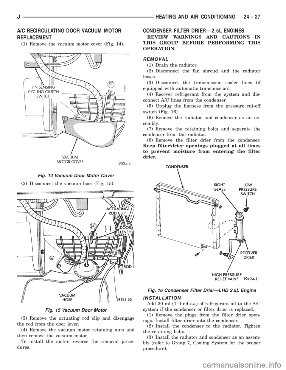
(1) Remove the vacuum motor cover (Fig. 14).
(2) Disconnect the vacuum hose (Fig. 15).
(3) Remove the actuating rod clip and disengage
the rod from the door lever.
(4) Remove the vacuum motor retaining nuts and
then remove the vacuum motor.
To install the motor, reverse the removal proce-
dures.
CONDENSER FILTER DRIERÐ2.5L ENGINES
REVIEW WARNINGS AND CAUTIONS IN
THIS GROUP BEFORE PERFORMING THIS
OPERATION.
REMOVAL
(1) Drain the radiator.
(2) Disconnect the fan shroud and the radiator
hoses.
(3) Disconnect the transmission cooler lines (if
equipped with automatic transmission).
(4) Recover refrigerant from the system and dis-
connect A/C lines from the condenser.
(5) Unplug the harness from the pressure cut-off
switch (Fig. 16).
(6) Remove the radiator and condenser as an as-
sembly.
(7) Remove the retaining bolts and separate the
condenser from the radiator.
(8) Remove the filter drier from the condenser.
Keep filter/drier openings plugged at all times
to prevent moisture from entering the filter
drier.
INSTALLATION
Add 30 ml (1 fluid oz.) of refrigerant oil to the A/C
system if the condenser or filter drier is replaced.
(1) Remove the plugs from the filter drier open-
ings. Install filter drier into the condenser.
(2) Install the condenser to the radiator. Tighten
the retaining bolts.
(3) Install the radiator and condenser as an assem-
bly (refer to Group 7, Cooling System for the proper
procedure).
Fig. 14 Vacuum Door Motor Cover
Fig. 15 Vacuum Door Motor
Fig. 16 Condenser Filter DrierÐLHD 2.5L Engine
JHEATING AND AIR CONDITIONING 24 - 27
Page 2108 of 2158
(4) Plug the harness into the low pressure switch
(Fig. 16).
(5) Connect the A/C hoses to the condenser.
(6) Connect the transmission cooler lines (if
equipped with automatic transmission).
(7) Connect the fan shroud and the radiator hoses.
(8) Fill coolant system (Refer to cooling for proper
procedure).
(9) Evacuate and charge the A/C system.
CONDENSERÐ4.0L ENGINES
REVIEW WARNINGS AND CAUTIONS IN
THIS GROUP BEFORE PERFORMING THIS
OPERATION.
REMOVAL
(1) Recover refrigerant from the system.
(2) Remove the upper radiator support.
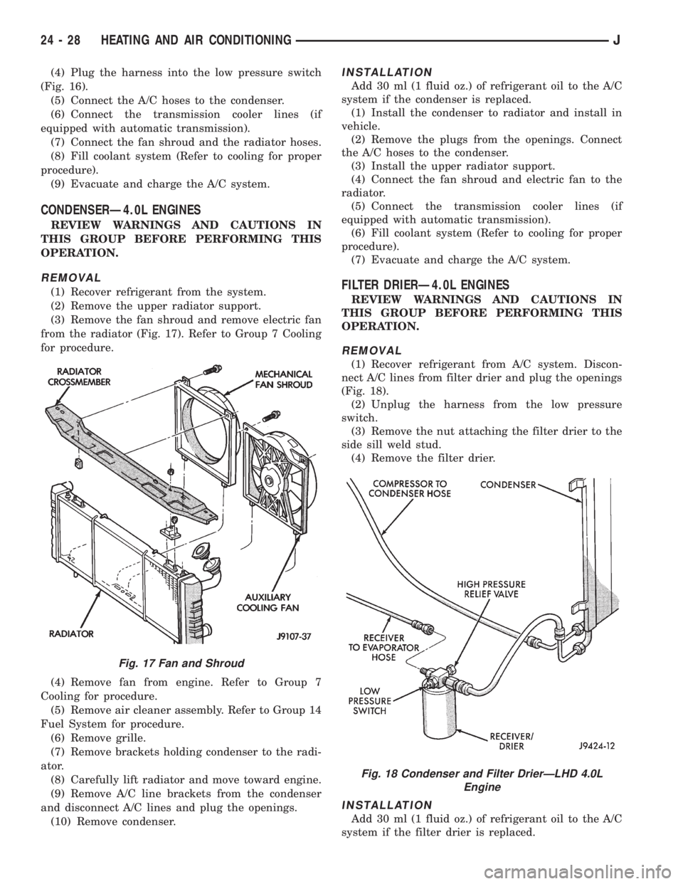
(3) Remove the fan shroud and remove electric fan
from the radiator (Fig. 17). Refer to Group 7 Cooling
for procedure.
(4) Remove fan from engine. Refer to Group 7
Cooling for procedure.
(5) Remove air cleaner assembly. Refer to Group 14
Fuel System for procedure.
(6) Remove grille.
(7) Remove brackets holding condenser to the radi-
ator.
(8) Carefully lift radiator and move toward engine.
(9) Remove A/C line brackets from the condenser
and disconnect A/C lines and plug the openings.
(10) Remove condenser.
INSTALLATION
Add 30 ml (1 fluid oz.) of refrigerant oil to the A/C
system if the condenser is replaced.
(1) Install the condenser to radiator and install in
vehicle.
(2) Remove the plugs from the openings. Connect
the A/C hoses to the condenser.
(3) Install the upper radiator support.
(4) Connect the fan shroud and electric fan to the
radiator.
(5) Connect the transmission cooler lines (if
equipped with automatic transmission).
(6) Fill coolant system (Refer to cooling for proper
procedure).
(7) Evacuate and charge the A/C system.
FILTER DRIERÐ4.0L ENGINES
REVIEW WARNINGS AND CAUTIONS IN
THIS GROUP BEFORE PERFORMING THIS
OPERATION.
REMOVAL
(1) Recover refrigerant from A/C system. Discon-
nect A/C lines from filter drier and plug the openings
(Fig. 18).
(2) Unplug the harness from the low pressure
switch.
(3) Remove the nut attaching the filter drier to the
side sill weld stud.
(4) Remove the filter drier.
INSTALLATION
Add 30 ml (1 fluid oz.) of refrigerant oil to the A/C
system if the filter drier is replaced.
Fig. 17 Fan and Shroud
Fig. 18 Condenser and Filter DrierÐLHD 4.0L
Engine
24 - 28 HEATING AND AIR CONDITIONINGJ