1995 JEEP YJ wheel torque
[x] Cancel search: wheel torquePage 1938 of 2158
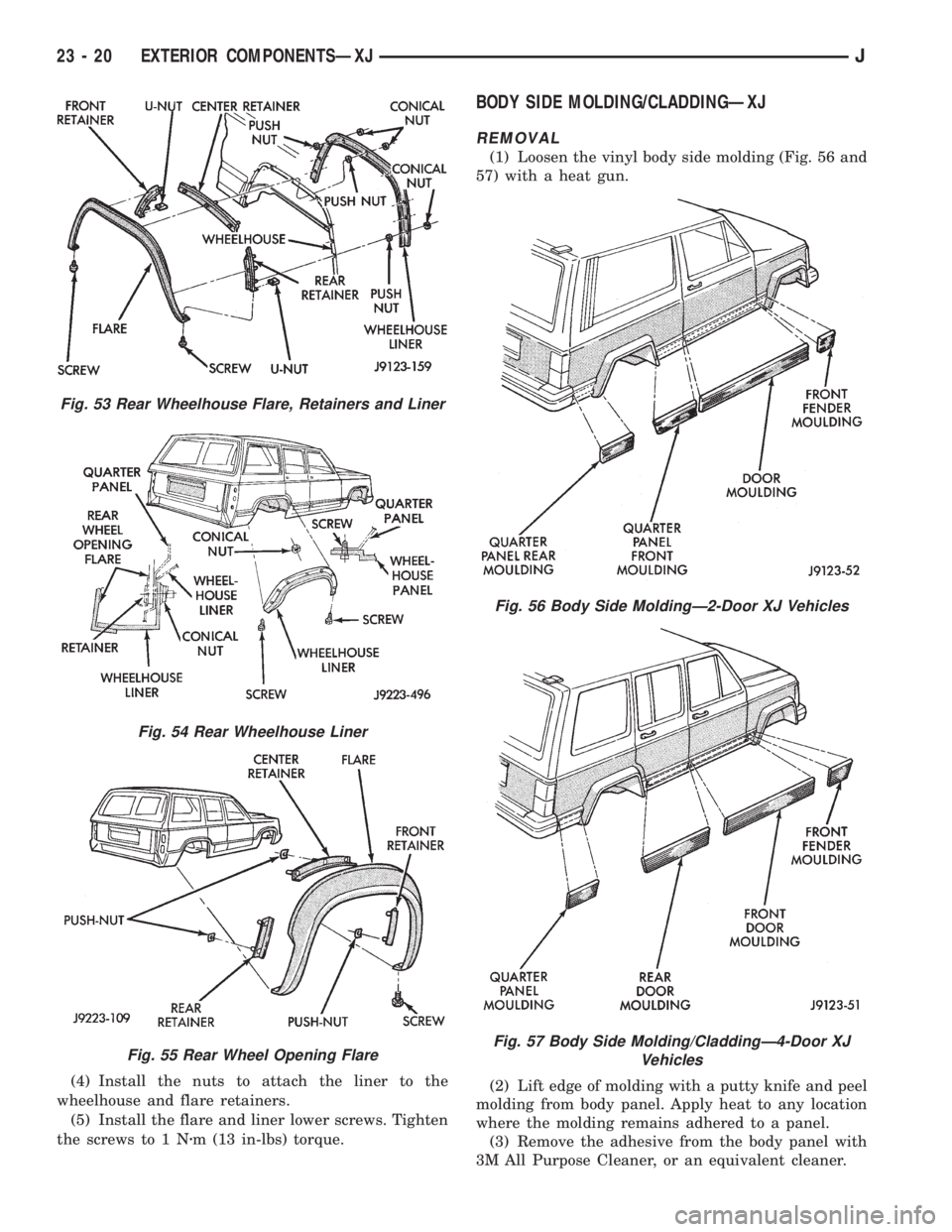
(4) Install the nuts to attach the liner to the
wheelhouse and flare retainers.
(5) Install the flare and liner lower screws. Tighten
the screws to 1 Nzm (13 in-lbs) torque.
BODY SIDE MOLDING/CLADDINGÐXJ
REMOVAL
(1) Loosen the vinyl body side molding (Fig. 56 and
57) with a heat gun.
(2) Lift edge of molding with a putty knife and peel
molding from body panel. Apply heat to any location
where the molding remains adhered to a panel.
(3) Remove the adhesive from the body panel with
3M All Purpose Cleaner, or an equivalent cleaner.
Fig. 53 Rear Wheelhouse Flare, Retainers and Liner
Fig. 54 Rear Wheelhouse Liner
Fig. 55 Rear Wheel Opening Flare
Fig. 56 Body Side MoldingÐ2-Door XJ Vehicles
Fig. 57 Body Side Molding/CladdingÐ4-Door XJ
Vehicles
23 - 20 EXTERIOR COMPONENTSÐXJJ
Page 1998 of 2158
INTERIOR COMPONENTS
INDEX
page page
Assist HandleÐXJ........................ 89
B/C-Pillar and Liftgate Pillar Trim CoversÐXJ.... 88
Bucket Seat Cushion and CoverÐXJ........... 81
Bucket Seat PlatformÐXJ................... 82
Bucket Seatback Cover and FrameÐXJ........ 81
Cargo BarrierÐXJ........................ 101
Cargo LampÐXJ......................... 94
Carpets and Floor MatsÐXJ................. 99
Dome LampÐXJ......................... 93
Front Bucket SeatsÐXJ.................... 81
Front Carpet/MatÐXJ...................... 99
Front Inner Scuff Plate/Cowl Side Trim PanelÐXJ . 86
Front Shoulder Belt/BuckleÐXJ............... 90
Full Floor ConsoleÐXJ..................... 95
HeadlinerÐXJ............................ 92
I/P Ash Receiver Tray LampÐXJ.............. 80
Instrument Cluster BezelÐXJ................ 80
Interior Trim Panels and Scuff PlatesÐXJ....... 84
Jack StorageÐXJ......................... 97
Keyless Entry ReceiverÐXJ................. 93Mini-Console with Floor ShiftÐXJ............. 94
Mini-Floor ConsoleÐXJ..................... 94
Outer Scuff PlatesÐXJ..................... 89
Overhead ConsoleÐXJ..................... 93
Parking Brake Handle CoverÐXJ............. 94
Quarter and Wheelhouse Trim PanelsÐXJ...... 87
Quarter Trim Panel ExtensionÐXJ............. 87
Rear Carpet/MatÐXJ..................... 100
Rear Seat Cushion CoverÐXJ............... 82
Rear Seat CushionÐXJ.................... 82
Rear Seatback CoverÐXJ................... 84
Rear Seatback Latch Striker and BumperÐXJ.... 84
Rear SeatbackÐXJ........................ 83
Rear Shoulder/Lap Belt/BuckleÐXJ............ 91
Sound BarÐXJ........................... 94
Spare Tire/Wheel Holddown and Floor
BracketsÐXJ........................... 98
SunvisorsÐXJ........................... 93
Windshield Side MoldingÐXJ................ 86
INSTRUMENT CLUSTER BEZELÐXJ
REMOVAL
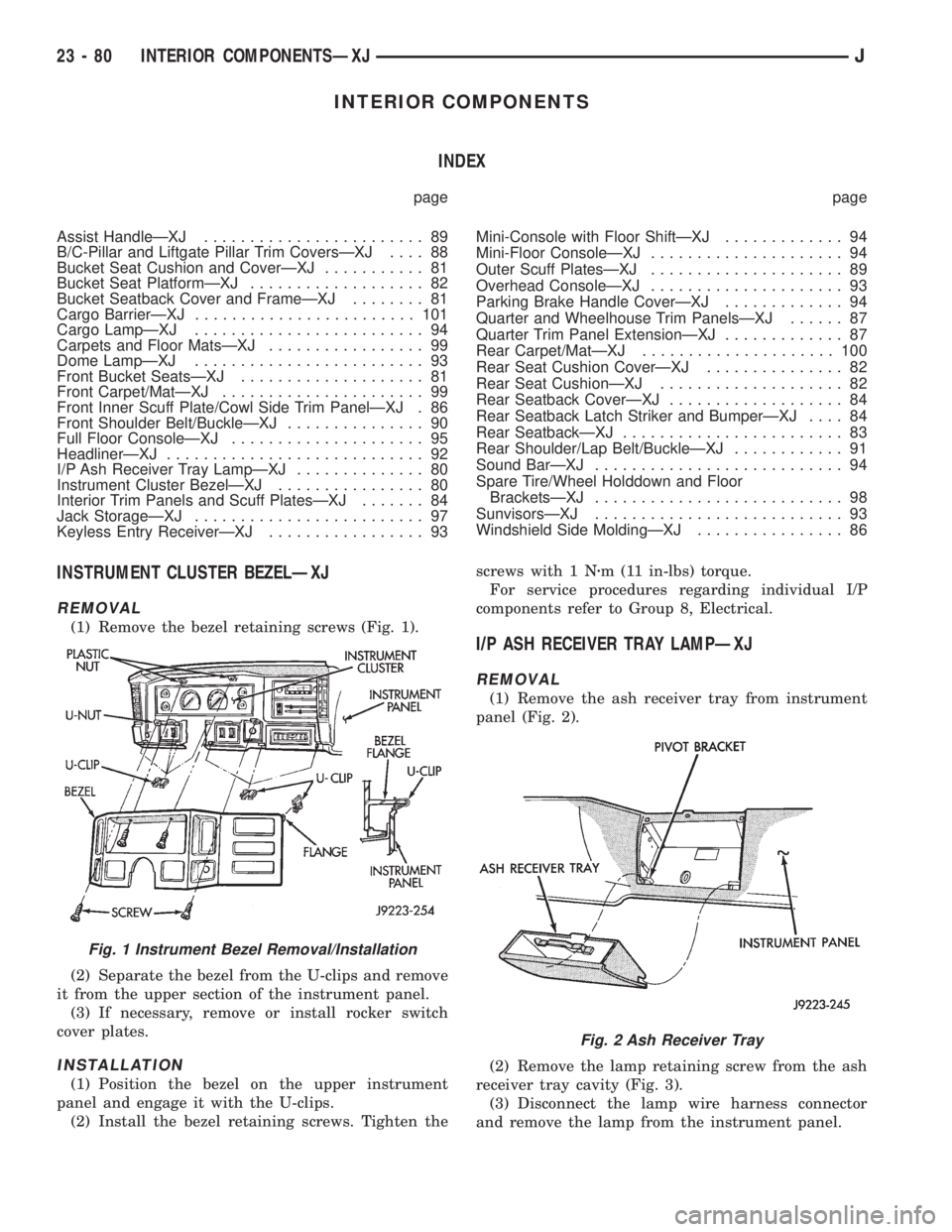
(1) Remove the bezel retaining screws (Fig. 1).
(2) Separate the bezel from the U-clips and remove
it from the upper section of the instrument panel.
(3) If necessary, remove or install rocker switch
cover plates.
INSTALLATION
(1) Position the bezel on the upper instrument
panel and engage it with the U-clips.
(2) Install the bezel retaining screws. Tighten thescrews with 1 Nzm (11 in-lbs) torque.
For service procedures regarding individual I/P
components refer to Group 8, Electrical.
I/P ASH RECEIVER TRAY LAMPÐXJ
REMOVAL
(1) Remove the ash receiver tray from instrument
panel (Fig. 2).
(2) Remove the lamp retaining screw from the ash
receiver tray cavity (Fig. 3).
(3) Disconnect the lamp wire harness connector
and remove the lamp from the instrument panel.
Fig. 1 Instrument Bezel Removal/Installation
Fig. 2 Ash Receiver Tray
23 - 80 INTERIOR COMPONENTSÐXJJ
Page 2001 of 2158
INSTALLATION
(1) Position the replacement cover on the cushion.
(2) Compress the cover and attach the retaining
clips to the front and rear wire retainers.
(3) Install the serrated retainers at the ends of the
cover.
(4) Install the seat cushion in the vehicle. If neces-
sary, refer to the installation procedure.
REAR SEATBACKÐXJ
REMOVAL
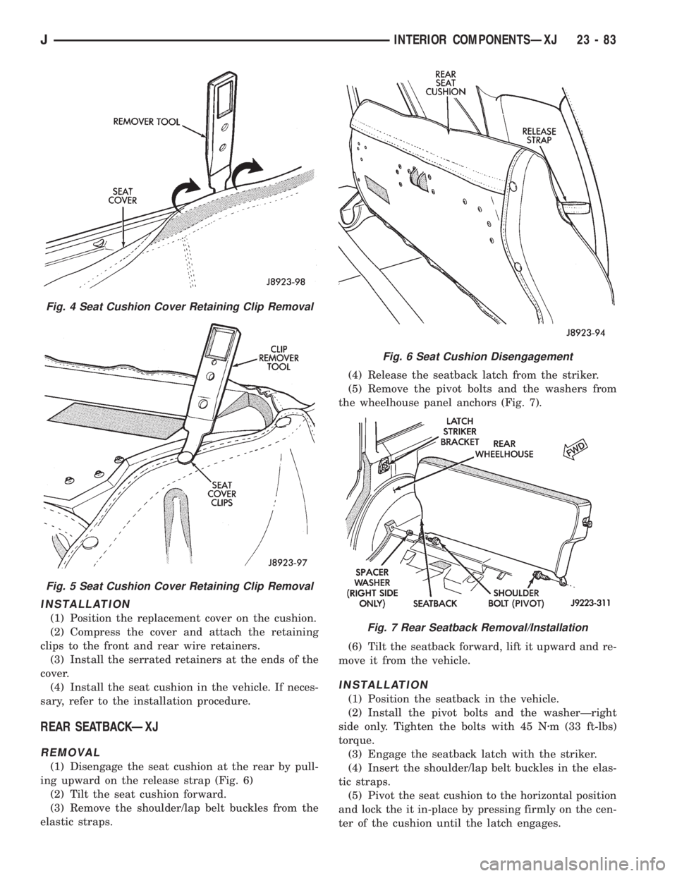
(1) Disengage the seat cushion at the rear by pull-
ing upward on the release strap (Fig. 6)
(2) Tilt the seat cushion forward.
(3) Remove the shoulder/lap belt buckles from the
elastic straps.(4) Release the seatback latch from the striker.
(5) Remove the pivot bolts and the washers from
the wheelhouse panel anchors (Fig. 7).
(6) Tilt the seatback forward, lift it upward and re-
move it from the vehicle.
INSTALLATION
(1) Position the seatback in the vehicle.
(2) Install the pivot bolts and the washerÐright
side only. Tighten the bolts with 45 Nzm (33 ft-lbs)
torque.
(3) Engage the seatback latch with the striker.
(4) Insert the shoulder/lap belt buckles in the elas-
tic straps.
(5) Pivot the seat cushion to the horizontal position
and lock the it in-place by pressing firmly on the cen-
ter of the cushion until the latch engages.
Fig. 4 Seat Cushion Cover Retaining Clip Removal
Fig. 5 Seat Cushion Cover Retaining Clip Removal
Fig. 6 Seat Cushion Disengagement
Fig. 7 Rear Seatback Removal/Installation
JINTERIOR COMPONENTSÐXJ 23 - 83
Page 2005 of 2158
(2) Install the headliner front trim molding, the
cowl side trim panel and the inner scuff plate in the
interior of the vehicle. Tighten the retaining screw to
1Nzm (11 in-lbs) torque.
QUARTER TRIM PANEL EXTENSIONÐXJ
REMOVAL
(1) Remove the retaining screws and the inner
scuff plate from the door sill.
(2) Remove the retaining screws and serrated re-
tainers, and remove the panel extension from the
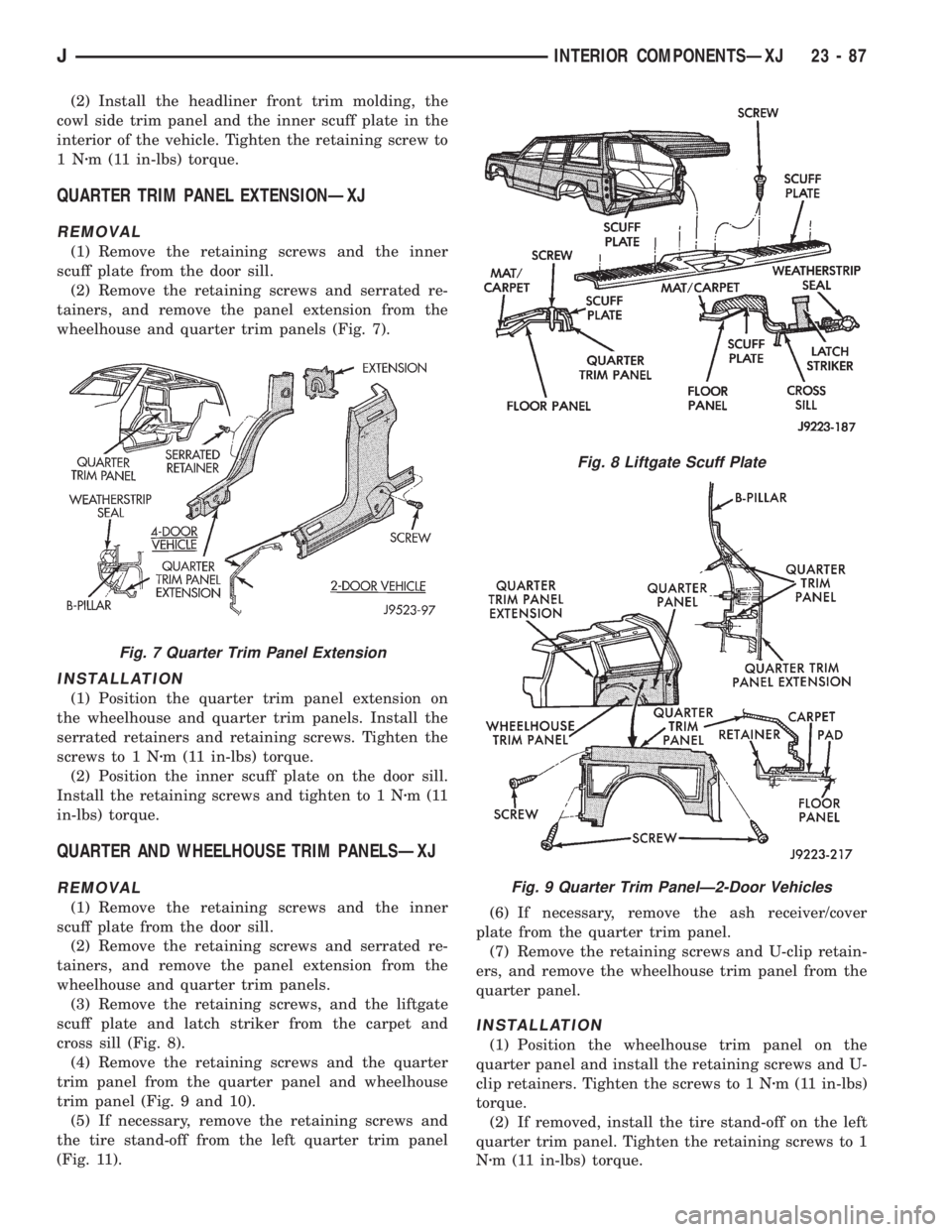
wheelhouse and quarter trim panels (Fig. 7).
INSTALLATION
(1) Position the quarter trim panel extension on
the wheelhouse and quarter trim panels. Install the
serrated retainers and retaining screws. Tighten the
screws to 1 Nzm (11 in-lbs) torque.
(2) Position the inner scuff plate on the door sill.
Install the retaining screws and tighten to 1 Nzm(11
in-lbs) torque.
QUARTER AND WHEELHOUSE TRIM PANELSÐXJ
REMOVAL
(1) Remove the retaining screws and the inner
scuff plate from the door sill.
(2) Remove the retaining screws and serrated re-
tainers, and remove the panel extension from the
wheelhouse and quarter trim panels.
(3) Remove the retaining screws, and the liftgate
scuff plate and latch striker from the carpet and
cross sill (Fig. 8).
(4) Remove the retaining screws and the quarter
trim panel from the quarter panel and wheelhouse
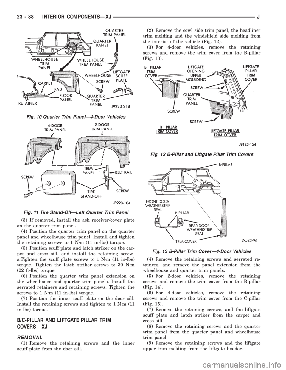
trim panel (Fig. 9 and 10).
(5) If necessary, remove the retaining screws and
the tire stand-off from the left quarter trim panel
(Fig. 11).(6) If necessary, remove the ash receiver/cover
plate from the quarter trim panel.
(7) Remove the retaining screws and U-clip retain-
ers, and remove the wheelhouse trim panel from the
quarter panel.
INSTALLATION
(1) Position the wheelhouse trim panel on the
quarter panel and install the retaining screws and U-
clip retainers. Tighten the screws to 1 Nzm (11 in-lbs)
torque.
(2) If removed, install the tire stand-off on the left
quarter trim panel. Tighten the retaining screws to 1
Nzm (11 in-lbs) torque.
Fig. 7 Quarter Trim Panel Extension
Fig. 8 Liftgate Scuff Plate
Fig. 9 Quarter Trim PanelÐ2-Door Vehicles
JINTERIOR COMPONENTSÐXJ 23 - 87
Page 2006 of 2158
(3) If removed, install the ash receiver/cover plate
on the quarter trim panel.
(4) Position the quarter trim panel on the quarter
panel and wheelhouse trim panel. Install and tighten
the retaining screws to 1 Nzm (11 in-lbs) torque.
(5) Position scuff plate and latch striker on the car-
pet and cross sill, and install the retaining screw-
s.Tighten the scuff plate screws to 1 Nzm (11 in-lbs)
torque. Tighten the latch striker screws to 30 Nzm
(22 ft-lbs) torque.
(6) Position the quarter trim panel extension on
the wheelhouse and quarter trim panels. Install the
serrated retainers and retaining screws. Tighten the
screws to 1 Nzm (11 in-lbs) torque.
(7) Position the inner scuff plate on the door sill.
Install the retaining screws and tighten to 1 Nzm(11
in-lbs) torque.
B/C-PILLAR AND LIFTGATE PILLAR TRIM
COVERSÐXJ
REMOVAL
(1) Remove the retaining screws and the inner
scuff plate from the door sill.(2) Remove the cowl side trim panel, the headliner
trim molding and the windshield side molding from
the interior of the vehicle (Fig. 12).
(3) For 4-door vehicles, remove the retaining
screws and remove the trim cover from the B-pillar
(Fig. 13).
(4) Remove the retaining screws and serrated re-
tainers, and remove the panel extension from the
wheelhouse and quarter trim panels.
(5) For 2-door vehicles, remove the retaining
screws and remove the trim cover from the B-pillar
(Fig. 14).
(6) For 4-door vehicles, remove the retaining
screws and remove the trim cover from the C-pillar
(Fig. 15).
(7) Remove the retaining screws, and the liftgate
scuff plate and latch striker from the carpet and
cross sill.
(8) Remove the retaining screws and the quarter
trim panel from the quarter panel and wheelhouse
trim panel.
(9) Remove the retaining screws and the liftgate
upper trim molding from the liftgate header.
Fig. 10 Quarter Trim PanelÐ4-Door Vehicles
Fig. 11 Tire Stand-OffÐLeft Quarter Trim Panel
Fig. 12 B-Pillar and Liftgate Pillar Trim Covers
Fig. 13 B-Pillar Trim CoverÐ4-Door Vehicles
23 - 88 INTERIOR COMPONENTSÐXJJ
Page 2007 of 2158
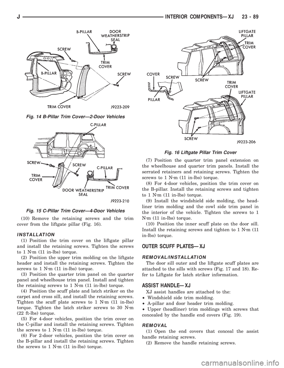
(10) Remove the retaining screws and the trim
cover from the liftgate pillar (Fig. 16).
INSTALLATION
(1) Position the trim cover on the liftgate pillar
and install the retaining screws. Tighten the screws
to1Nzm (11 in-lbs) torque.
(2) Position the upper trim molding on the liftgate
header and install the retaining screws. Tighten the
screws to 1 Nzm (11 in-lbs) torque.
(3) Position the quarter trim panel on the quarter
panel and wheelhouse trim panel. Install and tighten
the retaining screws to 1 Nzm (11 in-lbs) torque.
(4) Position the scuff plate and latch striker on the
carpet and cross sill, and install the retaining screws.
Tighten the scuff plate screws to 1 Nzm (11 in-lbs)
torque. Tighten the latch striker screws to 30 Nzm
(22 ft-lbs) torque.
(5) For 4-door vehicles, position the trim cover on
the C-pillar and install the retaining screws. Tighten
the screws to 1 Nzm (11 in-lbs) torque.
(6) For 2-door vehicles, position the trim cover on
the B-pillar and install the retaining screws. Tighten
the screws to 1 Nzm (11 in-lbs) torque.(7) Position the quarter trim panel extension on
the wheelhouse and quarter trim panels. Install the
serrated retainers and retaining screws. Tighten the
screws to 1 Nzm (11 in-lbs) torque.
(8) For 4-door vehicles, position the trim cover on
the B-pillar. Install the retaining screws and tighten
to1Nzm (11 in-lbs) torque.
(9) Install the windshield side molding, the head-
liner trim molding and the cowl side trim panel in
the interior of the vehicle. Tighten the screws to 1
Nzm (11 in-lbs) torque.
(10) Position the inner scuff plate on the door sill.
Install the retaining screws and tighten to 1 Nzm(11
in-lbs) torque.
OUTER SCUFF PLATESÐXJ
REMOVAL/INSTALLATION
The door sill outer and the liftgate scuff plates are
attached to the sills with screws (Fig. 17 and 18). Re-
fer to Liftgate for latch striker information.
ASSIST HANDLEÐXJ
XJ assist handles are attached to the:
²Windshield side trim molding.
²A-pillar and door header trim molding.
²Upper (headliner) trim moldings with screws that
concealed by the handle end covers (Fig. 19).
REMOVAL
(1) Open the end covers that conceal the assist
handle retaining screws.
(2) Remove the handle retaining screws.
Fig. 14 B-Pillar Trim CoverÐ2-Door Vehicles
Fig. 15 C-Pillar Trim CoverÐ4-Door Vehicles
Fig. 16 Liftgate Pillar Trim Cover
JINTERIOR COMPONENTSÐXJ 23 - 89
Page 2016 of 2158
SPARE TIRE/WHEEL HOLDDOWN AND FLOOR
BRACKETSÐXJ
REMOVAL
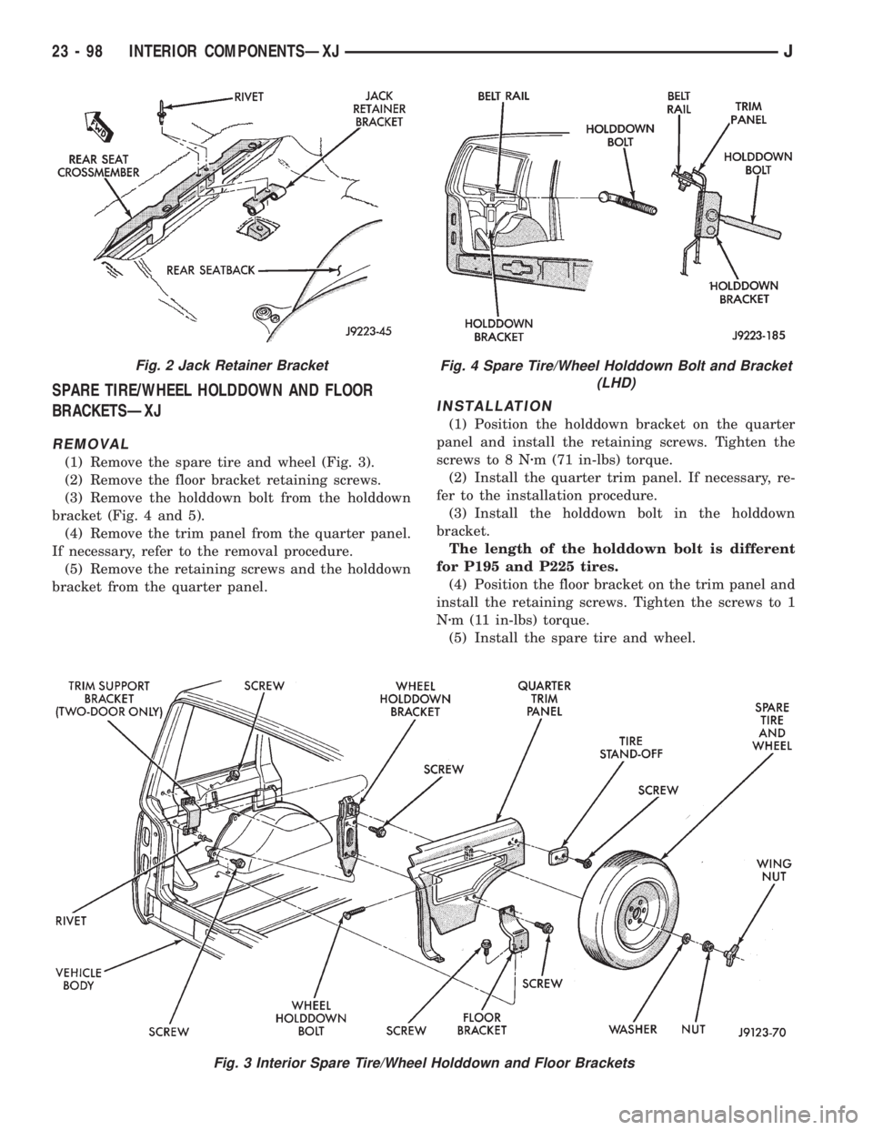
(1) Remove the spare tire and wheel (Fig. 3).
(2) Remove the floor bracket retaining screws.
(3) Remove the holddown bolt from the holddown
bracket (Fig. 4 and 5).
(4) Remove the trim panel from the quarter panel.
If necessary, refer to the removal procedure.
(5) Remove the retaining screws and the holddown
bracket from the quarter panel.
INSTALLATION
(1) Position the holddown bracket on the quarter
panel and install the retaining screws. Tighten the
screws to 8 Nzm (71 in-lbs) torque.
(2) Install the quarter trim panel. If necessary, re-
fer to the installation procedure.
(3) Install the holddown bolt in the holddown
bracket.
The length of the holddown bolt is different
for P195 and P225 tires.
(4) Position the floor bracket on the trim panel and
install the retaining screws. Tighten the screws to 1
Nzm (11 in-lbs) torque.
(5) Install the spare tire and wheel.
Fig. 3 Interior Spare Tire/Wheel Holddown and Floor Brackets
Fig. 2 Jack Retainer BracketFig. 4 Spare Tire/Wheel Holddown Bolt and Bracket
(LHD)
23 - 98 INTERIOR COMPONENTSÐXJJ
Page 2018 of 2158
REAR CARPET/MATÐXJ
REMOVAL
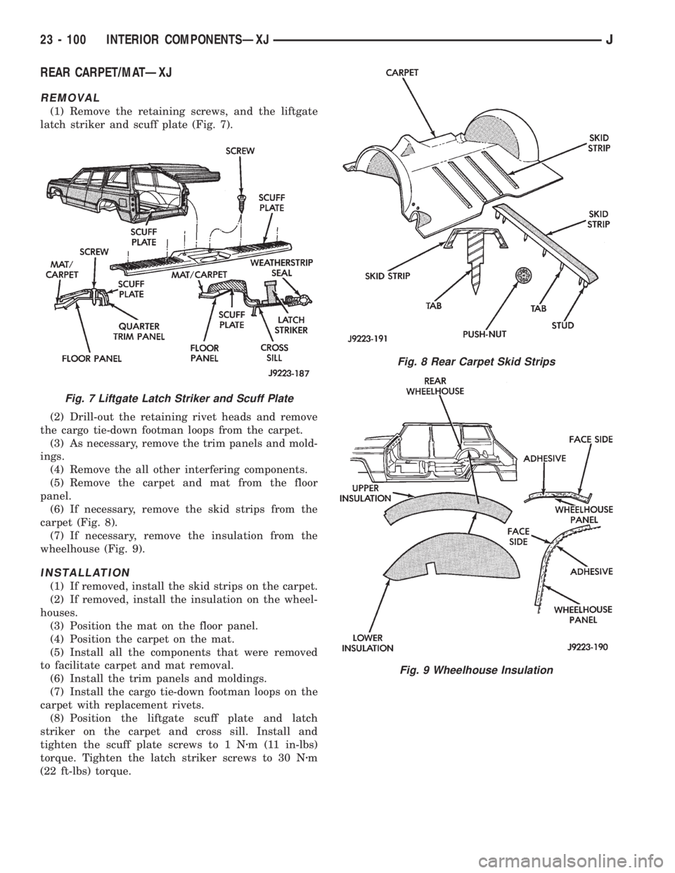
(1) Remove the retaining screws, and the liftgate
latch striker and scuff plate (Fig. 7).
(2) Drill-out the retaining rivet heads and remove
the cargo tie-down footman loops from the carpet.
(3) As necessary, remove the trim panels and mold-
ings.
(4) Remove the all other interfering components.
(5) Remove the carpet and mat from the floor
panel.
(6) If necessary, remove the skid strips from the
carpet (Fig. 8).
(7) If necessary, remove the insulation from the
wheelhouse (Fig. 9).
INSTALLATION
(1) If removed, install the skid strips on the carpet.
(2) If removed, install the insulation on the wheel-
houses.
(3) Position the mat on the floor panel.
(4) Position the carpet on the mat.
(5) Install all the components that were removed
to facilitate carpet and mat removal.
(6) Install the trim panels and moldings.
(7) Install the cargo tie-down footman loops on the
carpet with replacement rivets.
(8) Position the liftgate scuff plate and latch
striker on the carpet and cross sill. Install and
tighten the scuff plate screws to 1 Nzm (11 in-lbs)
torque. Tighten the latch striker screws to 30 Nzm
(22 ft-lbs) torque.
Fig. 7 Liftgate Latch Striker and Scuff Plate
Fig. 8 Rear Carpet Skid Strips
Fig. 9 Wheelhouse Insulation
23 - 100 INTERIOR COMPONENTSÐXJJ