1995 JEEP YJ automatic transmission
[x] Cancel search: automatic transmissionPage 1871 of 2158
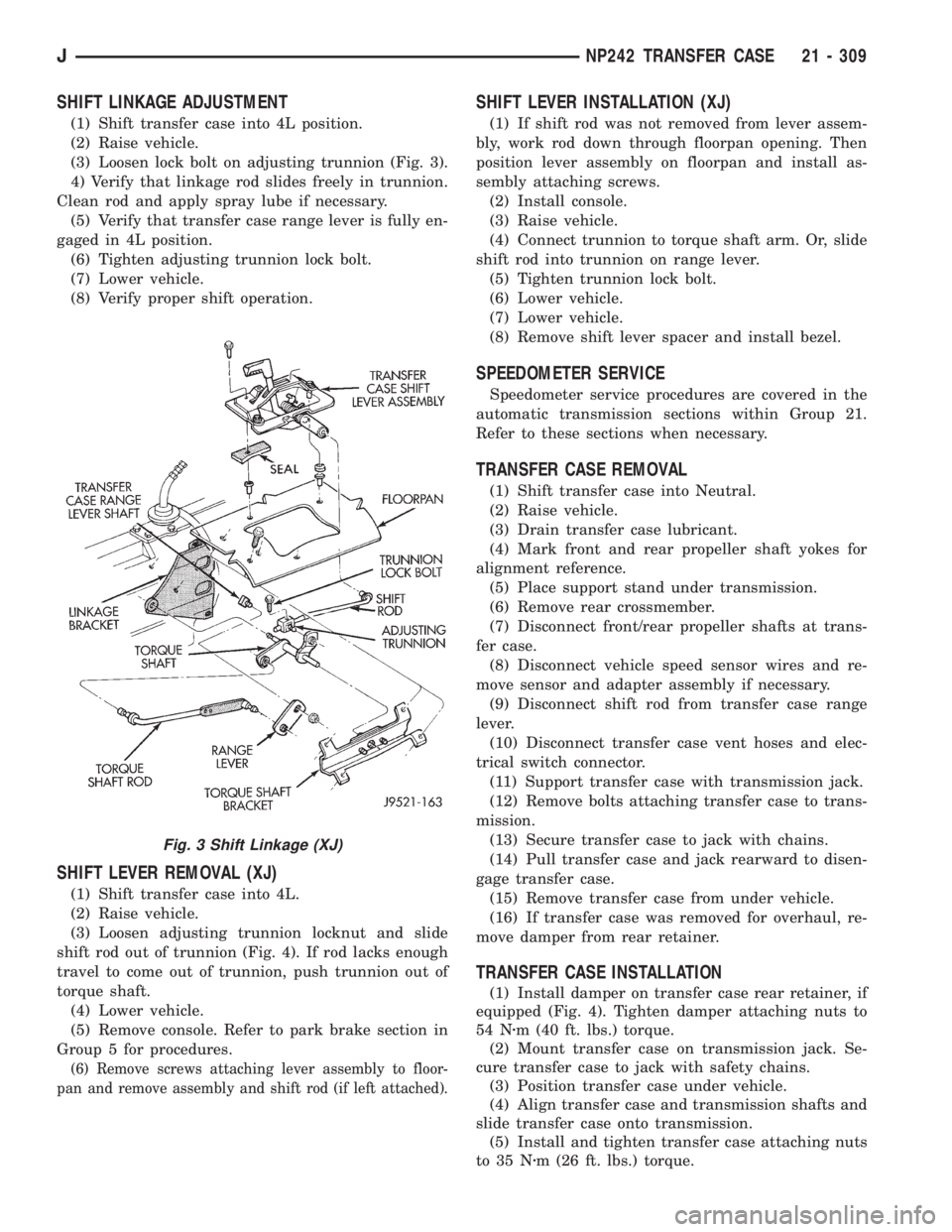
SHIFT LINKAGE ADJUSTMENT
(1) Shift transfer case into 4L position.
(2) Raise vehicle.
(3) Loosen lock bolt on adjusting trunnion (Fig. 3).
4) Verify that linkage rod slides freely in trunnion.
Clean rod and apply spray lube if necessary.
(5) Verify that transfer case range lever is fully en-
gaged in 4L position.
(6) Tighten adjusting trunnion lock bolt.
(7) Lower vehicle.
(8) Verify proper shift operation.
SHIFT LEVER REMOVAL (XJ)
(1) Shift transfer case into 4L.
(2) Raise vehicle.
(3) Loosen adjusting trunnion locknut and slide
shift rod out of trunnion (Fig. 4). If rod lacks enough
travel to come out of trunnion, push trunnion out of
torque shaft.
(4) Lower vehicle.
(5) Remove console. Refer to park brake section in
Group 5 for procedures.
(6) Remove screws attaching lever assembly to floor-
pan and remove assembly and shift rod (if left attached).
SHIFT LEVER INSTALLATION (XJ)
(1) If shift rod was not removed from lever assem-
bly, work rod down through floorpan opening. Then
position lever assembly on floorpan and install as-
sembly attaching screws.
(2) Install console.
(3) Raise vehicle.
(4) Connect trunnion to torque shaft arm. Or, slide
shift rod into trunnion on range lever.
(5) Tighten trunnion lock bolt.
(6) Lower vehicle.
(7) Lower vehicle.
(8) Remove shift lever spacer and install bezel.
SPEEDOMETER SERVICE
Speedometer service procedures are covered in the
automatic transmission sections within Group 21.
Refer to these sections when necessary.
TRANSFER CASE REMOVAL
(1) Shift transfer case into Neutral.
(2) Raise vehicle.
(3) Drain transfer case lubricant.
(4) Mark front and rear propeller shaft yokes for
alignment reference.
(5) Place support stand under transmission.
(6) Remove rear crossmember.
(7) Disconnect front/rear propeller shafts at trans-
fer case.
(8) Disconnect vehicle speed sensor wires and re-
move sensor and adapter assembly if necessary.
(9) Disconnect shift rod from transfer case range
lever.
(10) Disconnect transfer case vent hoses and elec-
trical switch connector.
(11) Support transfer case with transmission jack.
(12) Remove bolts attaching transfer case to trans-
mission.
(13) Secure transfer case to jack with chains.
(14) Pull transfer case and jack rearward to disen-
gage transfer case.
(15) Remove transfer case from under vehicle.
(16) If transfer case was removed for overhaul, re-
move damper from rear retainer.
TRANSFER CASE INSTALLATION
(1) Install damper on transfer case rear retainer, if
equipped (Fig. 4). Tighten damper attaching nuts to
54 Nzm (40 ft. lbs.) torque.
(2) Mount transfer case on transmission jack. Se-
cure transfer case to jack with safety chains.
(3) Position transfer case under vehicle.
(4) Align transfer case and transmission shafts and
slide transfer case onto transmission.
(5) Install and tighten transfer case attaching nuts
to 35 Nzm (26 ft. lbs.) torque.
Fig. 3 Shift Linkage (XJ)
JNP242 TRANSFER CASE 21 - 309
Page 1883 of 2158
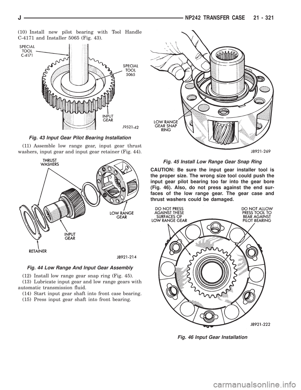
(10) Install new pilot bearing with Tool Handle
C-4171 and Installer 5065 (Fig. 43).
(11) Assemble low range gear, input gear thrust
washers, input gear and input gear retainer (Fig. 44).
(12) Install low range gear snap ring (Fig. 45).
(13) Lubricate input gear and low range gears with
automatic transmission fluid.
(14) Start input gear shaft into front case bearing.
(15) Press input gear shaft into front bearing.CAUTION: Be sure the input gear installer tool is
the proper size. The wrong size tool could push the
input gear pilot bearing too far into the gear bore
(Fig. 46). Also, do not press against the end sur-
faces of the low range gear. The gear case and
thrust washers could be damaged.
Fig. 43 Input Gear Pilot Bearing Installation
Fig. 44 Low Range And Input Gear Assembly
Fig. 45 Install Low Range Gear Snap Ring
Fig. 46 Input Gear Installation
JNP242 TRANSFER CASE 21 - 321
Page 1995 of 2158
TRAILER HITCH
TRAILER HITCHÐXJ
CLASS III HITCH
A class III weight-distributing/equalizer type hitch
can be used to tow a trailer:
²Having a maximum gross weight of 5,000 lbs/2250
kg.
²Having a maximum tongue weight of 750 lbs/332
kg).
The following vehicle basic equipment is required
for class III trailer towing:
²P205/75R15 or larger tires.
²Full size spare tire.
²Trailer sway control.
²Trailer tow wire harness and connector.
²Heavy duty turn signal flasher element.
²Heavy duty axle (with synthetic lubricant).
²Heavy duty cooling system.
²Heavy duty generator/battery.
²Auxiliary automatic transmission fluid cooler.
²I-6, 4.0L engine.
Wide-angle type door mirrors are recommended but
not required.
WIRE HARNESS CONNECTORS
CLASS I HITCH CONNECTOR
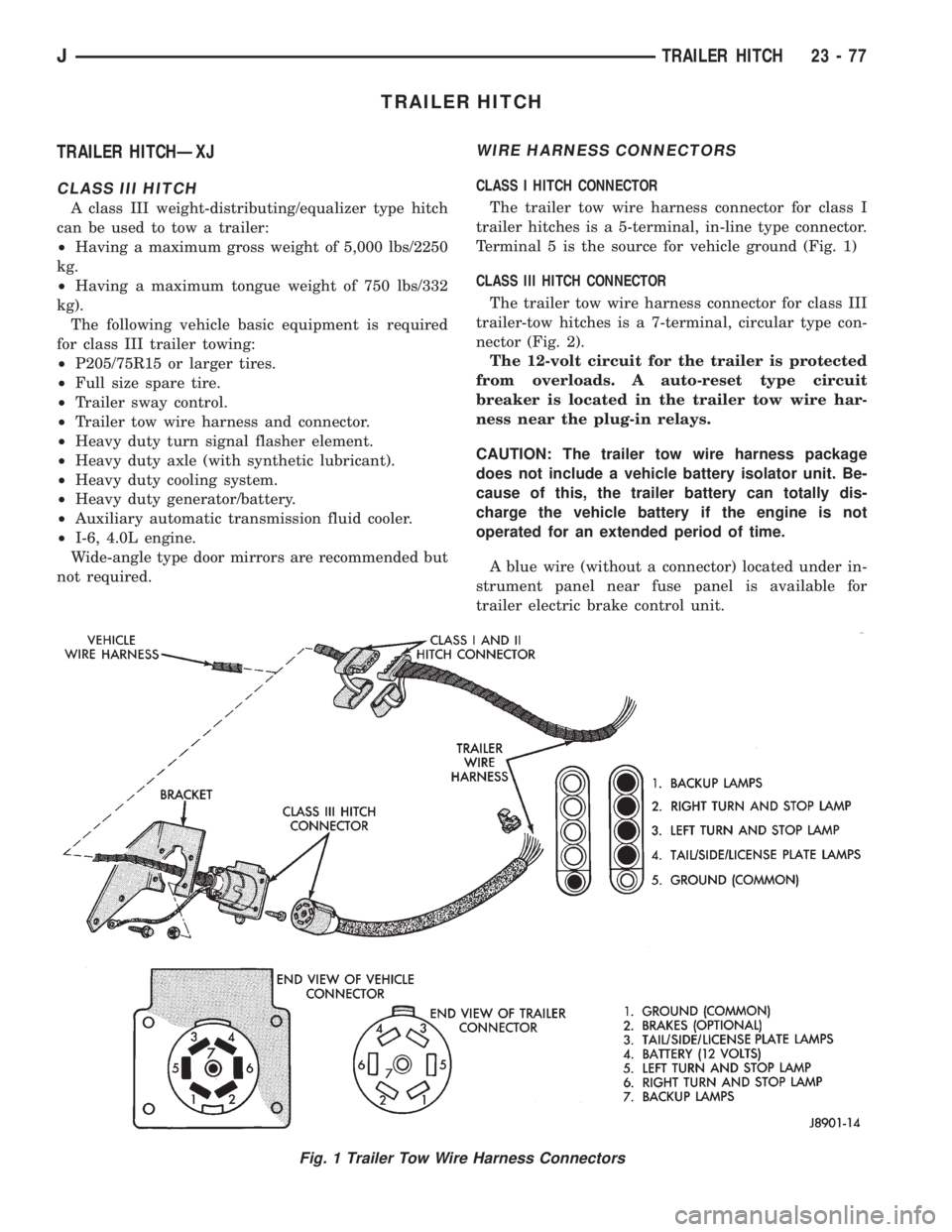
The trailer tow wire harness connector for class I
trailer hitches is a 5-terminal, in-line type connector.
Terminal 5 is the source for vehicle ground (Fig. 1)
CLASS III HITCH CONNECTOR
The trailer tow wire harness connector for class III
trailer-tow hitches is a 7-terminal, circular type con-
nector (Fig. 2).
The 12-volt circuit for the trailer is protected
from overloads. A auto-reset type circuit
breaker is located in the trailer tow wire har-
ness near the plug-in relays.
CAUTION: The trailer tow wire harness package
does not include a vehicle battery isolator unit. Be-
cause of this, the trailer battery can totally dis-
charge the vehicle battery if the engine is not
operated for an extended period of time.
A blue wire (without a connector) located under in-
strument panel near fuse panel is available for
trailer electric brake control unit.
Fig. 1 Trailer Tow Wire Harness Connectors
JTRAILER HITCH 23 - 77
Page 2012 of 2158
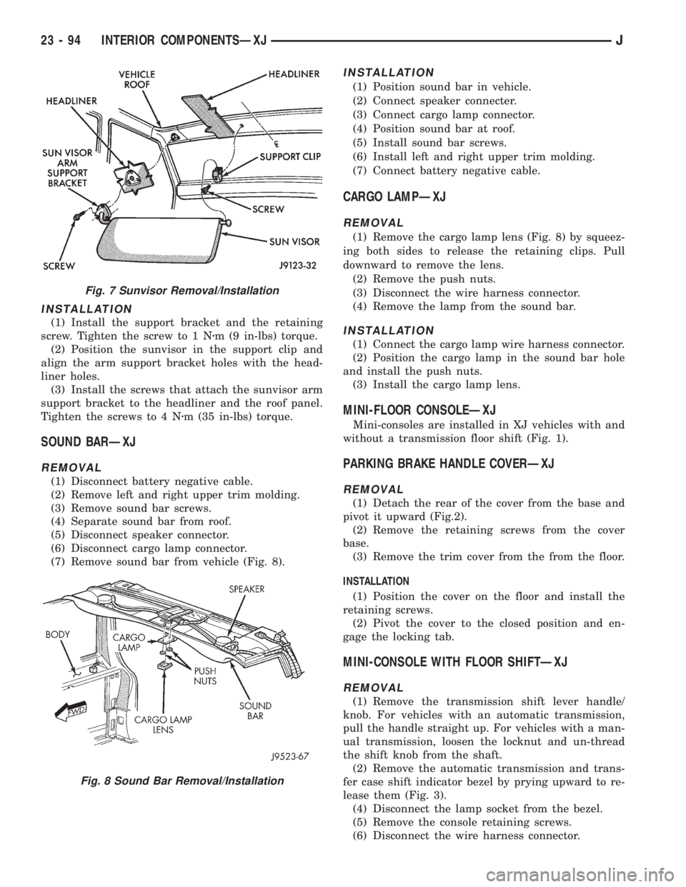
INSTALLATION
(1) Install the support bracket and the retaining
screw. Tighten the screw to 1 Nzm (9 in-lbs) torque.
(2) Position the sunvisor in the support clip and
align the arm support bracket holes with the head-
liner holes.
(3) Install the screws that attach the sunvisor arm
support bracket to the headliner and the roof panel.
Tighten the screws to 4 Nzm (35 in-lbs) torque.
SOUND BARÐXJ
REMOVAL
(1) Disconnect battery negative cable.
(2) Remove left and right upper trim molding.
(3) Remove sound bar screws.
(4) Separate sound bar from roof.
(5) Disconnect speaker connector.
(6) Disconnect cargo lamp connector.
(7) Remove sound bar from vehicle (Fig. 8).
INSTALLATION
(1) Position sound bar in vehicle.
(2) Connect speaker connecter.
(3) Connect cargo lamp connector.
(4) Position sound bar at roof.
(5) Install sound bar screws.
(6) Install left and right upper trim molding.
(7) Connect battery negative cable.
CARGO LAMPÐXJ
REMOVAL
(1) Remove the cargo lamp lens (Fig. 8) by squeez-
ing both sides to release the retaining clips. Pull
downward to remove the lens.
(2) Remove the push nuts.
(3) Disconnect the wire harness connector.
(4) Remove the lamp from the sound bar.
INSTALLATION
(1) Connect the cargo lamp wire harness connector.
(2) Position the cargo lamp in the sound bar hole
and install the push nuts.
(3) Install the cargo lamp lens.
MINI-FLOOR CONSOLEÐXJ
Mini-consoles are installed in XJ vehicles with and
without a transmission floor shift (Fig. 1).
PARKING BRAKE HANDLE COVERÐXJ
REMOVAL
(1) Detach the rear of the cover from the base and
pivot it upward (Fig.2).
(2) Remove the retaining screws from the cover
base.
(3) Remove the trim cover from the from the floor.
INSTALLATION
(1) Position the cover on the floor and install the
retaining screws.
(2) Pivot the cover to the closed position and en-
gage the locking tab.
MINI-CONSOLE WITH FLOOR SHIFTÐXJ
REMOVAL
(1) Remove the transmission shift lever handle/
knob. For vehicles with an automatic transmission,
pull the handle straight up. For vehicles with a man-
ual transmission, loosen the locknut and un-thread
the shift knob from the shaft.
(2) Remove the automatic transmission and trans-
fer case shift indicator bezel by prying upward to re-
lease them (Fig. 3).
(4) Disconnect the lamp socket from the bezel.
(5) Remove the console retaining screws.
(6) Disconnect the wire harness connector.
Fig. 7 Sunvisor Removal/Installation
Fig. 8 Sound Bar Removal/Installation
23 - 94 INTERIOR COMPONENTSÐXJJ
Page 2013 of 2158
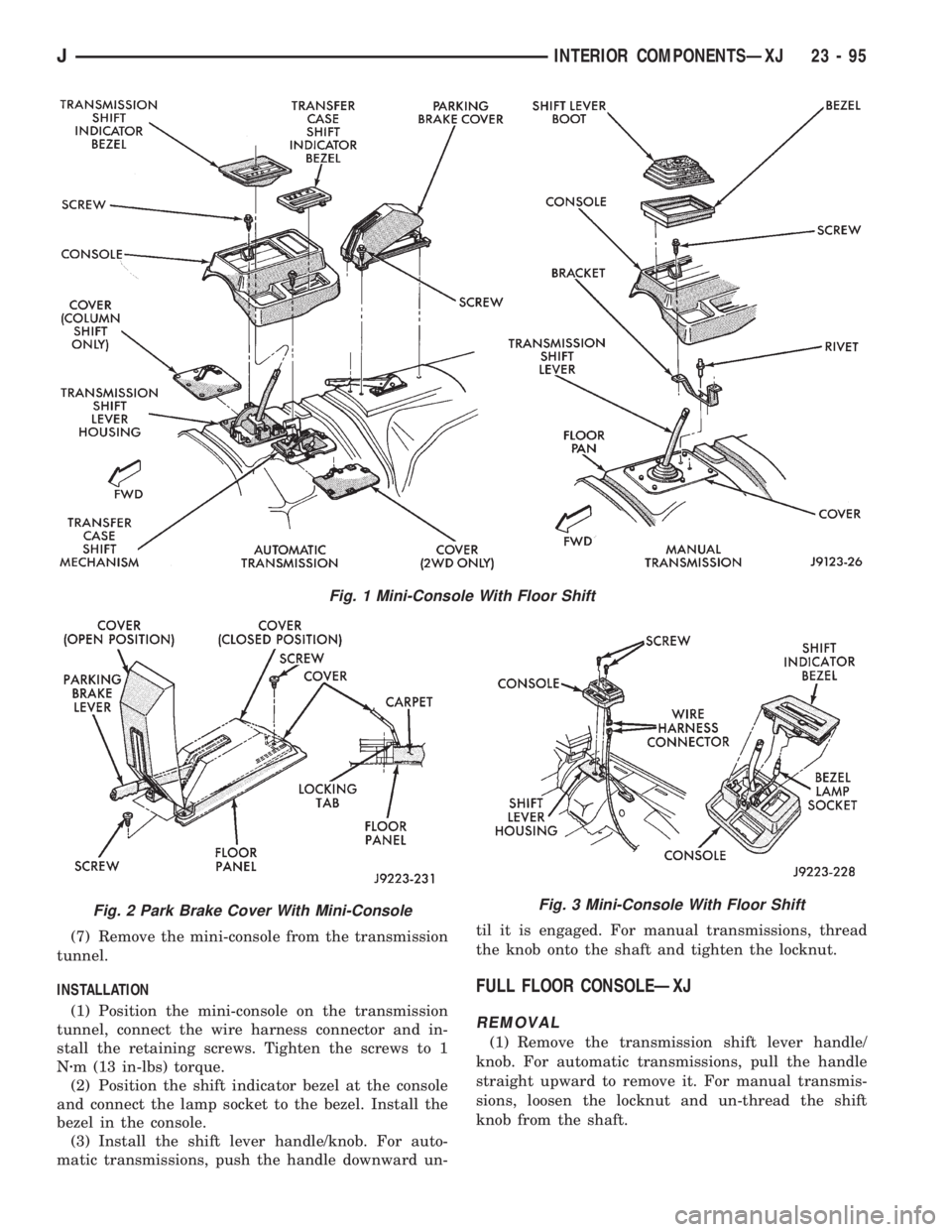
(7) Remove the mini-console from the transmission
tunnel.
INSTALLATION
(1) Position the mini-console on the transmission
tunnel, connect the wire harness connector and in-
stall the retaining screws. Tighten the screws to 1
Nzm (13 in-lbs) torque.
(2) Position the shift indicator bezel at the console
and connect the lamp socket to the bezel. Install the
bezel in the console.
(3) Install the shift lever handle/knob. For auto-
matic transmissions, push the handle downward un-til it is engaged. For manual transmissions, thread
the knob onto the shaft and tighten the locknut.
FULL FLOOR CONSOLEÐXJ
REMOVAL
(1) Remove the transmission shift lever handle/
knob. For automatic transmissions, pull the handle
straight upward to remove it. For manual transmis-
sions, loosen the locknut and un-thread the shift
knob from the shaft.
Fig. 1 Mini-Console With Floor Shift
Fig. 2 Park Brake Cover With Mini-ConsoleFig. 3 Mini-Console With Floor Shift
JINTERIOR COMPONENTSÐXJ 23 - 95
Page 2014 of 2158
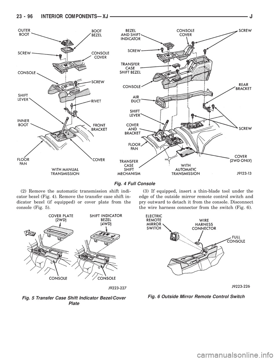
(2) Remove the automatic transmission shift indi-
cator bezel (Fig. 4). Remove the transfer case shift in-
dicator bezel (if equipped) or cover plate from the
console (Fig. 5).(3) If equipped, insert a thin-blade tool under the
edge of the outside mirror remote control switch and
pry outward to detach it from the console. Disconnect
the wire harness connector from the switch (Fig. 6).
Fig. 4 Full Console
Fig. 5 Transfer Case Shift Indicator Bezel/Cover
PlateFig. 6 Outside Mirror Remote Control Switch
23 - 96 INTERIOR COMPONENTSÐXJJ
Page 2107 of 2158
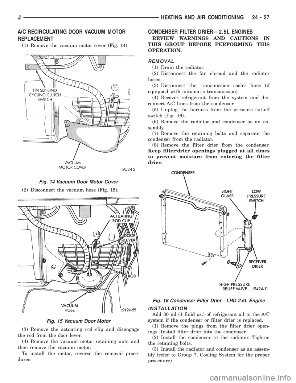
A/C RECIRCULATING DOOR VACUUM MOTOR
REPLACEMENT
(1) Remove the vacuum motor cover (Fig. 14).
(2) Disconnect the vacuum hose (Fig. 15).
(3) Remove the actuating rod clip and disengage
the rod from the door lever.
(4) Remove the vacuum motor retaining nuts and
then remove the vacuum motor.
To install the motor, reverse the removal proce-
dures.
CONDENSER FILTER DRIERÐ2.5L ENGINES
REVIEW WARNINGS AND CAUTIONS IN
THIS GROUP BEFORE PERFORMING THIS
OPERATION.
REMOVAL
(1) Drain the radiator.
(2) Disconnect the fan shroud and the radiator
hoses.
(3) Disconnect the transmission cooler lines (if
equipped with automatic transmission).
(4) Recover refrigerant from the system and dis-
connect A/C lines from the condenser.
(5) Unplug the harness from the pressure cut-off
switch (Fig. 16).
(6) Remove the radiator and condenser as an as-
sembly.
(7) Remove the retaining bolts and separate the
condenser from the radiator.
(8) Remove the filter drier from the condenser.
Keep filter/drier openings plugged at all times
to prevent moisture from entering the filter
drier.
INSTALLATION
Add 30 ml (1 fluid oz.) of refrigerant oil to the A/C
system if the condenser or filter drier is replaced.
(1) Remove the plugs from the filter drier open-
ings. Install filter drier into the condenser.
(2) Install the condenser to the radiator. Tighten
the retaining bolts.
(3) Install the radiator and condenser as an assem-
bly (refer to Group 7, Cooling System for the proper
procedure).
Fig. 14 Vacuum Door Motor Cover
Fig. 15 Vacuum Door Motor
Fig. 16 Condenser Filter DrierÐLHD 2.5L Engine
JHEATING AND AIR CONDITIONING 24 - 27
Page 2108 of 2158
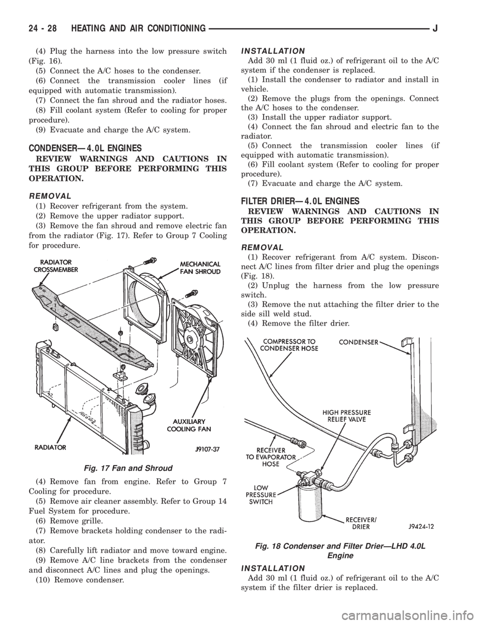
(4) Plug the harness into the low pressure switch
(Fig. 16).
(5) Connect the A/C hoses to the condenser.
(6) Connect the transmission cooler lines (if
equipped with automatic transmission).
(7) Connect the fan shroud and the radiator hoses.
(8) Fill coolant system (Refer to cooling for proper
procedure).
(9) Evacuate and charge the A/C system.
CONDENSERÐ4.0L ENGINES
REVIEW WARNINGS AND CAUTIONS IN
THIS GROUP BEFORE PERFORMING THIS
OPERATION.
REMOVAL
(1) Recover refrigerant from the system.
(2) Remove the upper radiator support.
(3) Remove the fan shroud and remove electric fan
from the radiator (Fig. 17). Refer to Group 7 Cooling
for procedure.
(4) Remove fan from engine. Refer to Group 7
Cooling for procedure.
(5) Remove air cleaner assembly. Refer to Group 14
Fuel System for procedure.
(6) Remove grille.
(7) Remove brackets holding condenser to the radi-
ator.
(8) Carefully lift radiator and move toward engine.
(9) Remove A/C line brackets from the condenser
and disconnect A/C lines and plug the openings.
(10) Remove condenser.
INSTALLATION
Add 30 ml (1 fluid oz.) of refrigerant oil to the A/C
system if the condenser is replaced.
(1) Install the condenser to radiator and install in
vehicle.
(2) Remove the plugs from the openings. Connect
the A/C hoses to the condenser.
(3) Install the upper radiator support.
(4) Connect the fan shroud and electric fan to the
radiator.
(5) Connect the transmission cooler lines (if
equipped with automatic transmission).
(6) Fill coolant system (Refer to cooling for proper
procedure).
(7) Evacuate and charge the A/C system.
FILTER DRIERÐ4.0L ENGINES
REVIEW WARNINGS AND CAUTIONS IN
THIS GROUP BEFORE PERFORMING THIS
OPERATION.
REMOVAL
(1) Recover refrigerant from A/C system. Discon-
nect A/C lines from filter drier and plug the openings
(Fig. 18).
(2) Unplug the harness from the low pressure
switch.
(3) Remove the nut attaching the filter drier to the
side sill weld stud.
(4) Remove the filter drier.
INSTALLATION
Add 30 ml (1 fluid oz.) of refrigerant oil to the A/C
system if the filter drier is replaced.
Fig. 17 Fan and Shroud
Fig. 18 Condenser and Filter DrierÐLHD 4.0L
Engine
24 - 28 HEATING AND AIR CONDITIONINGJ