Page 1559 of 2158
(4) Remove pressure and return line bracket at
belt tensioner (Fig. 5).
INSTALLATION
(1) Wipe hose ends, pump and gear unions clean.(2) Install pressure and return line on the pump
and gear (Fig. 2, 3, 4).
(3) Align the pressure and return line bracket to
the tensioner bracket. Install the screw. Tighten the
screw to 28 Nzm (21 ft. lbs.) torque.
Fig. 4 Fluid Lines At Pump
Fig. 5 Pressure And Return Line Routing
Fig. 3 Pressure And Return Lines
JSTEERING 19 - 75
Page 1560 of 2158
(4) Tighten fittings at pump and gear to 28 Nzm
(21 ft. lbs.) torque.
(5) After installation, add power steering fluid, in-
spect and test for fluid leaks.
PUMP REPLACEMENT
REMOVAL
(1) Remove and cap pressure and return lines from
pump. Refer to Pressure and Return Line Replace-
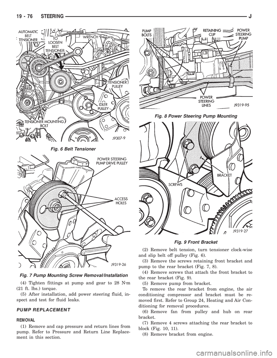
ment in this section.(2) Remove belt tension, turn tensioner clock-wise
and slip belt off pulley (Fig. 6).
(3) Remove the screws retaining front bracket and
pump to the rear bracket (Fig. 7, 8).
(4) Remove screws that attach the front bracket to
the rear bracket (Fig. 9).
(5) Remove pump from bracket.
To remove the rear bracket from engine, the air
conditioning compressor and bracket must be re-
moved first. Refer to Group 24, Heating and Air Con-
ditioning for removal procedures.
(6) Remove fan from pulley and hub on rear
bracket.
(7) Remove 4 screws attaching the rear bracket to
block (Fig. 10, 11).
(8) Remove bracket from engine.
Fig. 6 Belt Tensioner
Fig. 7 Pump Mounting Screw Removal/Installation
Fig. 8 Power Steering Pump Mounting
Fig. 9 Front Bracket
19 - 76 STEERINGJ
Page 1561 of 2158
INSTALLATION
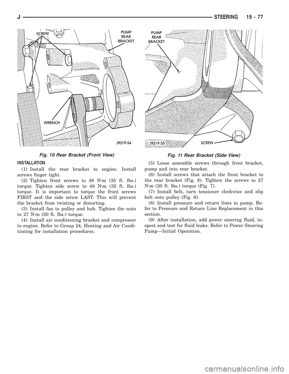
(1) Install the rear bracket to engine. Install
screws finger tight.
(2) Tighten front screws to 48 Nzm (35 ft. lbs.)
torque. Tighten side screw to 48 Nzm (35 ft. lbs.)
torque. It is important to torque the front screws
FIRST and the side screw LAST. This will prevent
the bracket from twisting or distorting.
(3) Install fan to pulley and hub. Tighten the nuts
to 27 Nzm (20 ft. lbs.) torque.
(4) Install air conditioning bracket and compressor
to engine. Refer to Group 24, Heating and Air Condi-
tioning for installation procedures.(5) Loose assemble screws through front bracket,
pump and into rear bracket.
(6) Install screws that attach the front bracket to
the rear bracket (Fig. 8). Tighten the screws to 27
Nzm (20 ft. lbs.) torque (Fig. 7).
(7) Install belt, turn tensioner clockwise and slip
belt onto pulley (Fig. 6).
(8) Install pressure and return lines to pump. Re-
fer to Pressure and Return Line Replacement in this
section.
(9) After installation, add power steering fluid, in-
spect and test for fluid leaks. Refer to Power Steering
PumpÐInitial Operation.
Fig. 11 Rear Bracket (Side View)Fig. 10 Rear Bracket (Front View)
JSTEERING 19 - 77
Page 1917 of 2158
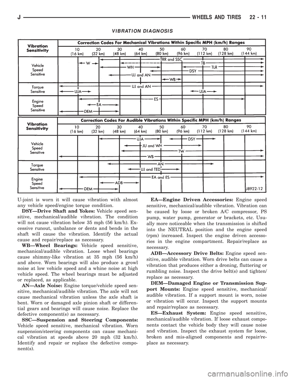
U-joint is worn it will cause vibration with almost
any vehicle speed/engine torque condition.
DSYÐDrive Shaft and Yokes:Vehicle speed sen-
sitive, mechanical/audible vibration. The condition
will not cause vibration below 35 mph (56 km/h). Ex-
cessive runout, unbalance or dents and bends in the
shaft will cause the vibration. Identify the actual
cause and repair/replace as necessary.
WBÐWheel Bearings:Vehicle speed sensitive,
mechanical/audible vibration. Loose wheel bearings
cause shimmy-like vibration at 35 mph (56 km/h)
and above. Worn bearings will also produce a growl
noise at low vehicle speed and a whine noise at high
vehicle speed. The wheel bearings must be adjusted
or replaced, as applicable.
ANÐAxle Noise:Engine torque/vehicle speed sen-
sitive, mechanical/audible vibration. The axle will not
cause mechanical vibration unless the axle shaft is
bent. Worn or damaged axle pinion shaft or differen-
tial gears and bearings will cause noise. Replace the
defective component(s) as necessary.
SSCÐSuspension and Steering Components:
Vehicle speed sensitive, mechanical vibration. Worn
suspension/steering components can cause mechani-
cal vibration at speeds above 20 mph (32 km/h).
Identify and repair or replace the defective compo-
nent(s).EAÐEngine Driven Accessories:Engine speed
sensitive, mechanical/audible vibration. Vibration can
be caused by loose or broken A/C compressor, PS
pump, water pump, generator or brackets, etc. Usu-
ally more noticeable when the transmission is shifted
into the NEUTRAL position and the engine speed
(rpm) increased. Inspect the engine driven accesso-
ries in the engine compartment. Repair/replace as
necessary.
ADBÐAccessory Drive Belts:Engine speed sen-
sitive, audible vibration. Worn drive belts can cause a
vibration that produces either a droning, fluttering or
rumbling noise. Inspect the drive belt(s) and tighten/
replace as necessary.
DEMÐDamaged Engine or Transmission Sup-
port Mounts:Engine speed sensitive, mechanical/
audible vibration. If a support mount is worn, noise
or vibration will occur. Inspect the support mounts
and repair/replace as necessary.
ESÐExhaust System:Engine speed sensitive,
mechanical/audible vibration. If loose exhaust compo-
nents contact the vehicle body they will cause noise
and vibration. Inspect the exhaust system for loose,
broken and mis-aligned components and repair/re-
place as necessary.
VIBRATION DIAGNOSIS
JWHEELS AND TIRES 22 - 11
Page 1961 of 2158
(4) Tighten the regulator-to-glass screw to 4 Nzm
(36 in-lbs) torque.
(5) Install the glass channel bottom screw (Fig.
17). Tighten screw to 9 Nzm (7 ft-lbs) torque.(6) Attach the door waterdam to the door inner
panel with sealant.
(7) Install the trim panel.
FRONT DOOR WINDOW GLASSÐXJ
REMOVAL
(1) Remove the door trim panel and waterdam.
(2) Remove the window glass channel hardware,
beltline molding and weatherstrip seals (Fig. 25 and
26).
(3) Remove the glass channel bottom screw.
(4) Remove the regulator-to-window glass screw,
bushing and retainer (Fig. 20).
(5) Lift the glass upward and out of the door.
Fig. 21 Manual Regulator InstallationÐUpper Rivets
Fig. 22 Manual Regulator InstallationÐLower Rivets
and Glass Retaining Screw
Fig. 23 Power Regulator InstallationÐUpper Rivets
Fig. 24 Power Regulator InstallationÐLower Rivets
Fig. 25 Front Door Beltline Molding and
Weatherstrip Seals
JDOORSÐXJ 23 - 43
Page 1962 of 2158
INSTALLATION
(1) Position the glass in the door and install the
regulator-to-glass retainer, bushing and screw.
(2) Tighten the screw to 4 Nzm (36 in-lbs) torque.
(3) Install the channel bottom screw. Tighten the
screw to 9 Nzm (7 ft-lbs) torque.
(4) Install the channel hardware, beltline molding
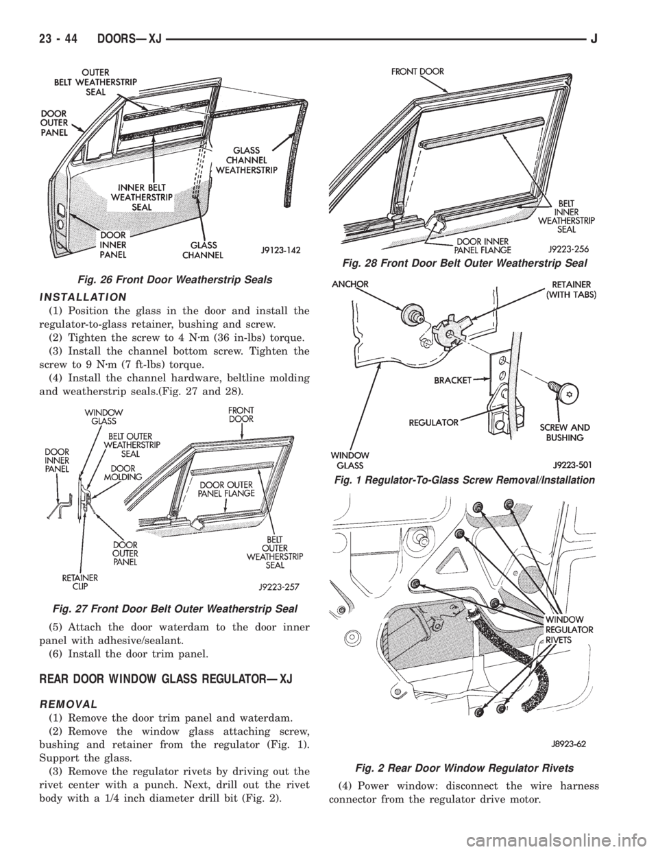
and weatherstrip seals.(Fig. 27 and 28).
(5) Attach the door waterdam to the door inner
panel with adhesive/sealant.
(6) Install the door trim panel.
REAR DOOR WINDOW GLASS REGULATORÐXJ
REMOVAL
(1) Remove the door trim panel and waterdam.
(2) Remove the window glass attaching screw,
bushing and retainer from the regulator (Fig. 1).
Support the glass.
(3) Remove the regulator rivets by driving out the
rivet center with a punch. Next, drill out the rivet
body with a 1/4 inch diameter drill bit (Fig. 2).(4) Power window: disconnect the wire harness
connector from the regulator drive motor.
Fig. 26 Front Door Weatherstrip Seals
Fig. 27 Front Door Belt Outer Weatherstrip Seal
Fig. 28 Front Door Belt Outer Weatherstrip Seal
Fig. 1 Regulator-To-Glass Screw Removal/Installation
Fig. 2 Rear Door Window Regulator Rivets
23 - 44 DOORSÐXJJ
Page 1963 of 2158
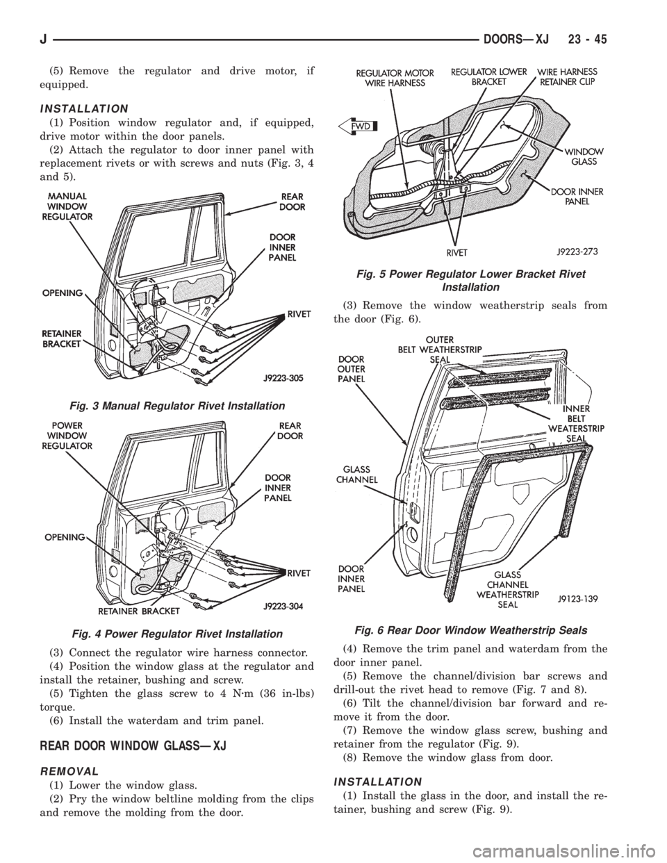
(5) Remove the regulator and drive motor, if
equipped.
INSTALLATION
(1) Position window regulator and, if equipped,
drive motor within the door panels.
(2) Attach the regulator to door inner panel with
replacement rivets or with screws and nuts (Fig. 3, 4
and 5).
(3) Connect the regulator wire harness connector.
(4) Position the window glass at the regulator and
install the retainer, bushing and screw.
(5) Tighten the glass screw to 4 Nzm (36 in-lbs)
torque.
(6) Install the waterdam and trim panel.
REAR DOOR WINDOW GLASSÐXJ
REMOVAL
(1) Lower the window glass.
(2) Pry the window beltline molding from the clips
and remove the molding from the door.(3) Remove the window weatherstrip seals from
the door (Fig. 6).
(4) Remove the trim panel and waterdam from the
door inner panel.
(5) Remove the channel/division bar screws and
drill-out the rivet head to remove (Fig. 7 and 8).
(6) Tilt the channel/division bar forward and re-
move it from the door.
(7) Remove the window glass screw, bushing and
retainer from the regulator (Fig. 9).
(8) Remove the window glass from door.INSTALLATION
(1) Install the glass in the door, and install the re-
tainer, bushing and screw (Fig. 9).
Fig. 3 Manual Regulator Rivet Installation
Fig. 4 Power Regulator Rivet Installation
Fig. 5 Power Regulator Lower Bracket Rivet
Installation
Fig. 6 Rear Door Window Weatherstrip Seals
JDOORSÐXJ 23 - 45
Page 1964 of 2158
(2) Tighten the glass attaching screw 6 Nzm (53 in-
lbs) torque.(3) Install the window glass channel/division bar in
the door.
(4) Install the window glass channel/division bar
screws and rivet. Tighten the screws to 6 Nzm(5ft-
lbs) torque.
(5) Install the window glass channel and belt
weatherstrip seals (Fig. 10 and 11).
(6) Install the window beltline molding.
(7) Install the door waterdam and trim panel.
REAR DOOR STATIONARY WINDOW GLASSÐXJ
REMOVAL
(1) Lower the window glass.
(2) Pry the window beltline molding away from the
clips and remove the molding from the door.
Fig. 7 Window Channel/Division Bar Screws and
Rivet
Fig. 8 Window Channel/Division Bar Rivet
Fig. 9 Regulator-To-Glass Screw Removal/
Installation
Fig. 10 Glass Channel Weatherstrip Seal
Fig. 11 Belt Weatherstrip Seals
23 - 46 DOORSÐXJJ