1995 JEEP YJ differential
[x] Cancel search: differentialPage 175 of 2158
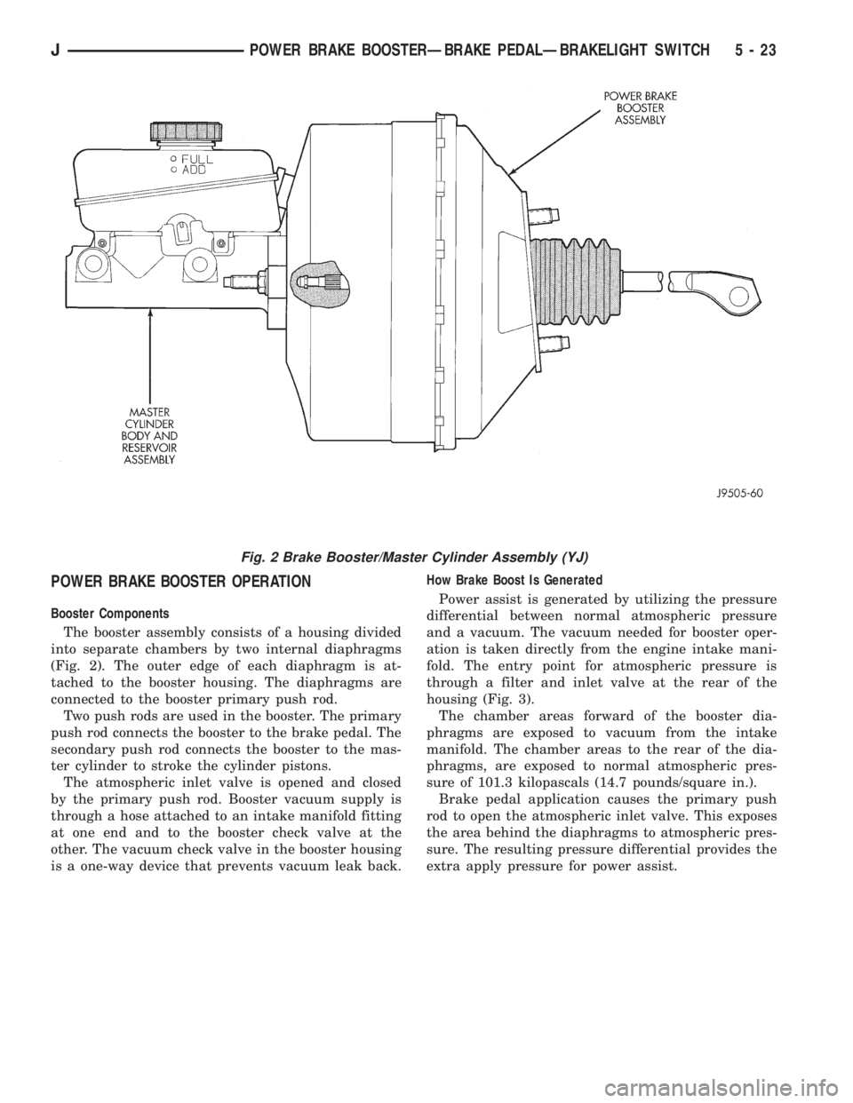
POWER BRAKE BOOSTER OPERATION
Booster Components
The booster assembly consists of a housing divided
into separate chambers by two internal diaphragms
(Fig. 2). The outer edge of each diaphragm is at-
tached to the booster housing. The diaphragms are
connected to the booster primary push rod.
Two push rods are used in the booster. The primary
push rod connects the booster to the brake pedal. The
secondary push rod connects the booster to the mas-
ter cylinder to stroke the cylinder pistons.
The atmospheric inlet valve is opened and closed
by the primary push rod. Booster vacuum supply is
through a hose attached to an intake manifold fitting
at one end and to the booster check valve at the
other. The vacuum check valve in the booster housing
is a one-way device that prevents vacuum leak back.How Brake Boost Is Generated
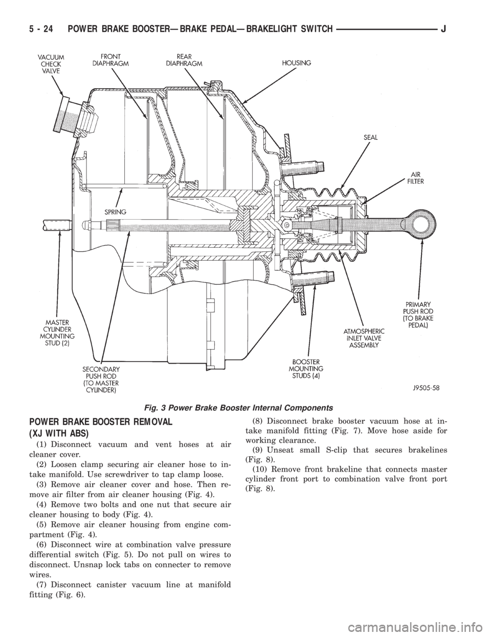
Power assist is generated by utilizing the pressure
differential between normal atmospheric pressure
and a vacuum. The vacuum needed for booster oper-
ation is taken directly from the engine intake mani-
fold. The entry point for atmospheric pressure is
through a filter and inlet valve at the rear of the
housing (Fig. 3).
The chamber areas forward of the booster dia-
phragms are exposed to vacuum from the intake
manifold. The chamber areas to the rear of the dia-
phragms, are exposed to normal atmospheric pres-
sure of 101.3 kilopascals (14.7 pounds/square in.).
Brake pedal application causes the primary push
rod to open the atmospheric inlet valve. This exposes
the area behind the diaphragms to atmospheric pres-
sure. The resulting pressure differential provides the
extra apply pressure for power assist.
Fig. 2 Brake Booster/Master Cylinder Assembly (YJ)
JPOWER BRAKE BOOSTERÐBRAKE PEDALÐBRAKELIGHT SWITCH 5 - 23
Page 176 of 2158
POWER BRAKE BOOSTER REMOVAL
(XJ WITH ABS)
(1) Disconnect vacuum and vent hoses at air
cleaner cover.
(2) Loosen clamp securing air cleaner hose to in-
take manifold. Use screwdriver to tap clamp loose.
(3) Remove air cleaner cover and hose. Then re-
move air filter from air cleaner housing (Fig. 4).
(4) Remove two bolts and one nut that secure air
cleaner housing to body (Fig. 4).
(5) Remove air cleaner housing from engine com-
partment (Fig. 4).
(6) Disconnect wire at combination valve pressure
differential switch (Fig. 5). Do not pull on wires to
disconnect. Unsnap lock tabs on connecter to remove
wires.
(7) Disconnect canister vacuum line at manifold
fitting (Fig. 6).(8) Disconnect brake booster vacuum hose at in-
take manifold fitting (Fig. 7). Move hose aside for
working clearance.
(9) Unseat small S-clip that secures brakelines
(Fig. 8).
(10) Remove front brakeline that connects master
cylinder front port to combination valve front port
(Fig. 8).
Fig. 3 Power Brake Booster Internal Components
5 - 24 POWER BRAKE BOOSTERÐBRAKE PEDALÐBRAKELIGHT SWITCHJ
Page 177 of 2158
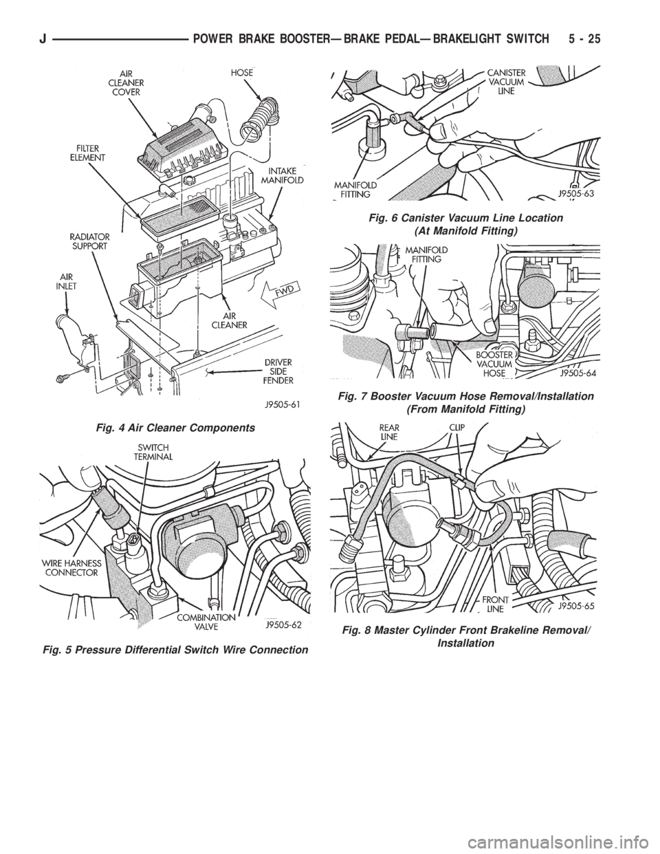
Fig. 4 Air Cleaner Components
Fig. 5 Pressure Differential Switch Wire Connection
Fig. 6 Canister Vacuum Line Location
(At Manifold Fitting)
Fig. 7 Booster Vacuum Hose Removal/Installation
(From Manifold Fitting)
Fig. 8 Master Cylinder Front Brakeline Removal/
Installation
JPOWER BRAKE BOOSTERÐBRAKE PEDALÐBRAKELIGHT SWITCH 5 - 25
Page 181 of 2158
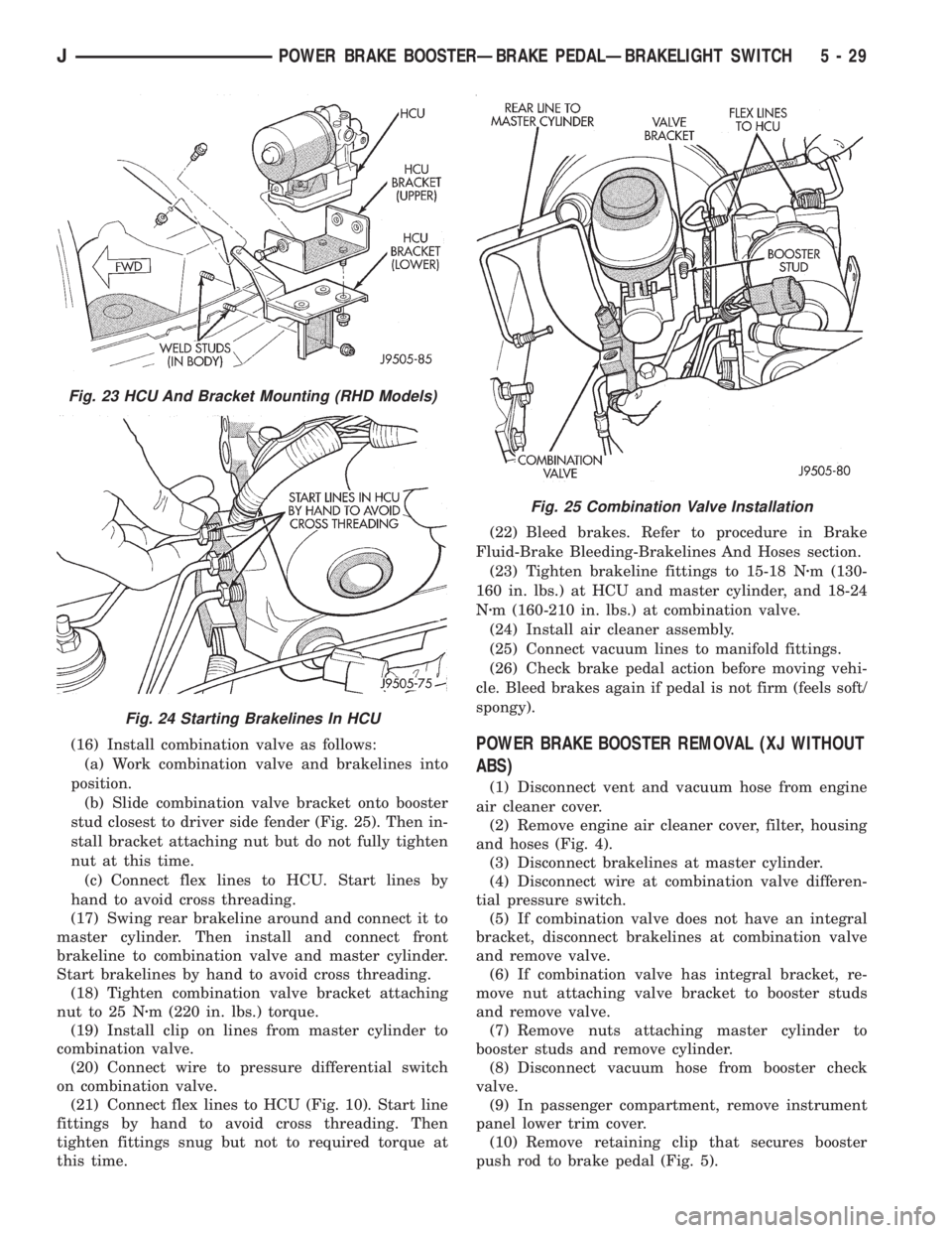
(16) Install combination valve as follows:
(a) Work combination valve and brakelines into
position.
(b) Slide combination valve bracket onto booster
stud closest to driver side fender (Fig. 25). Then in-
stall bracket attaching nut but do not fully tighten
nut at this time.
(c) Connect flex lines to HCU. Start lines by
hand to avoid cross threading.
(17) Swing rear brakeline around and connect it to
master cylinder. Then install and connect front
brakeline to combination valve and master cylinder.
Start brakelines by hand to avoid cross threading.
(18) Tighten combination valve bracket attaching
nut to 25 Nzm (220 in. lbs.) torque.
(19) Install clip on lines from master cylinder to
combination valve.
(20) Connect wire to pressure differential switch
on combination valve.
(21) Connect flex lines to HCU (Fig. 10). Start line
fittings by hand to avoid cross threading. Then
tighten fittings snug but not to required torque at
this time.(22) Bleed brakes. Refer to procedure in Brake
Fluid-Brake Bleeding-Brakelines And Hoses section.
(23) Tighten brakeline fittings to 15-18 Nzm (130-
160 in. lbs.) at HCU and master cylinder, and 18-24
Nzm (160-210 in. lbs.) at combination valve.
(24) Install air cleaner assembly.
(25) Connect vacuum lines to manifold fittings.
(26) Check brake pedal action before moving vehi-
cle. Bleed brakes again if pedal is not firm (feels soft/
spongy).POWER BRAKE BOOSTER REMOVAL (XJ WITHOUT
ABS)
(1) Disconnect vent and vacuum hose from engine
air cleaner cover.
(2) Remove engine air cleaner cover, filter, housing
and hoses (Fig. 4).
(3) Disconnect brakelines at master cylinder.
(4) Disconnect wire at combination valve differen-
tial pressure switch.
(5) If combination valve does not have an integral
bracket, disconnect brakelines at combination valve
and remove valve.
(6) If combination valve has integral bracket, re-
move nut attaching valve bracket to booster studs
and remove valve.
(7) Remove nuts attaching master cylinder to
booster studs and remove cylinder.
(8) Disconnect vacuum hose from booster check
valve.
(9) In passenger compartment, remove instrument
panel lower trim cover.
(10) Remove retaining clip that secures booster
push rod to brake pedal (Fig. 5).
Fig. 23 HCU And Bracket Mounting (RHD Models)
Fig. 24 Starting Brakelines In HCU
Fig. 25 Combination Valve Installation
JPOWER BRAKE BOOSTERÐBRAKE PEDALÐBRAKELIGHT SWITCH 5 - 29
Page 186 of 2158

MASTER CYLINDER/POWER BRAKE BOOSTER
A 25 mm bore master cylinder and 205 mm (8.07
in.) dual diaphragm power brake booster are used for
all ABS applications (Fig. 2).
The master cylinder has a removable plastic reser-
voir which is the only serviceable component. The
cylinder body and pistons are not repairable and are
serviced as an assembly. The check valve and grom-
met are the only serviceable parts on the booster.
The booster itself is only serviced as an assembly.
COMBINATION VALVE
A combination valve is used with the ABS system
(Fig. 2). The valve contains a front/rear brake pres-
sure differential switch and rear brake proportioning
valve. The combination valve is connected between
the master cylinder and HCU.
The pressure differential switch is connected to the
red brake warning light. The switch is actuated by
movement of the switch valve. The switch monitors
fluid pressure in the separate front/rear brake hy-
draulic circuits.
A decrease or loss of fluid pressure in either hy-
draulic circuit will cause the switch valve to shuttle
forward or rearward in response to the pressure dif-
ferential. Movement of the switch valve will push the
switch plunger upward. This closes the switch inter-
nal contacts completing the electrical circuit to the
red warning light. The switch valve remains in an
actuated position until the fault is repaired.
The rear proportioning valve is used to balance front-
rear brake action.
ELECTRONIC CONTROL UNIT (ECU)
A separate electronic control unit (ECU) operates
the ABS system (Fig. 3). The ECU is separate from
other vehicle electrical circuits. ECU voltage source
is through the ignition switch in the Run position.The ECU is located under the instrument panel in
the passenger compartment. On YJ models, it is just
above the heater plenum in line with the glove box.
In left hand drive XJ models, it at the right side of
the steering column. In right hand drive models, it is
near the cowl panel
The ECU contains dual microprocessors. A logic
block in each microprocessor receives identical sensor
signals. These signals are processed and compared si-
multaneously.
The ECU contains a self check program that illu-
minates the ABS warning light when a system fault
is detected. Faults are stored in a diagnostic program
memory and are accessible with the DRB scan tool.
ABS faults remain in memory until cleared, or un-
til after the vehicle is started approximately 50
times. Stored faults arenoterased if the battery is
disconnected.
WHEEL SPEED SENSORS
A speed sensor is used at each wheel. The sensors
convert wheel speed into an electrical signal. This
signal is transmitted to the antilock ECU.
A gear type tone ring serves as the trigger mecha-
nism for each sensor. The tone rings are mounted at
the outboard ends of the front and rear axle shafts.
Different sensors are used at the front and rear
wheels (Fig. 4). The front/rear sensors have the same
electrical values but are not interchangeable.
Fig. 2 ABS Master Cylinder-Booster-Combination
Valve-HCU
Fig. 3 Antilock ECU
5 - 34 ABS OPERATION AND SERVICEJ
Page 1632 of 2158
30RH/32RH TRANSMISSION DIAGNOSIS
INDEX
page page
Air Pressure Test......................... 74
Analyzing the Road Test.................... 71
Converter Housing Leak Diagnosis............ 75
Converter Stall Test........................ 74
Diagnosis Guides and Charts................ 77
Effects of Incorrect Fluid Level............... 71
Fluid Level Check......................... 70Gearshift Cable/Linkage Adjustment........... 71
General Information....................... 70
Hydraulic Pressure Test.................... 72
Preliminary Diagnosis...................... 70
Road Test............................... 71
Transmission Throttle Valve Cable Adjustment.... 71
GENERAL INFORMATION
Automatic transmission problems are generally a
result of:
²poor engine performance
²incorrect fluid level
²incorrect throttle valve cable adjustment
²incorrect band adjustment
²incorrect hydraulic control pressure adjustments
²hydraulic component malfunctions
²mechanical component malfunctions.
Begin diagnosis by checking the easily accessible
items such as fluid level, fluid condition and control
linkage adjustment. A road test will determine if fur-
ther diagnosis is necessary.
Procedures outlined in this section should be per-
formed in the following sequence to realize the most
accurate results:
²Preliminary diagnosis
²Check fluid level and condition
²Check control linkage Adjustment
²Road test
²Stall test
²Hydraulic pressure test
²Air pressure tests
²Leak test
²Analyze test results and consult diagnosis charts
PRELIMINARY DIAGNOSIS
Two basic procedures are required. One procedure
for vehicles that are driveable and an alternate pro-
cedure for disabled vehicles (will not back up or move
forward).
Vehicle Is Driveable
(1) Check fluid level and condition.
(2) Adjust throttle cable and gearshift linkage if
complaint was based on delayed, erratic, or harsh
shifts.
(3) Road test vehicle and note transmission operat-
ing characteristics.(4) Perform stall test if complaint is based on slug-
gish, low speed acceleration or abnormal throttle
opening needed to maintain normal speeds with
properly tuned engine.
(5) Perform hydraulic pressure tests.
(6) Perform air pressure test to check clutch-band
operation.
Vehicle Is Disabled
(1) Check fluid level and condition.
(2) Check for broken, disconnected throttle linkage.
(3) Check for cracked, leaking cooler lines, or loose,
missing pressure port plugs.
(4) Raise vehicle, start engine, shift transmission
into gear and note following:
(a) If propeller shafts turn but wheels do not,
problem is with differential or axle shafts.
(b) If propeller shafts do not turn and transmis-
sion is noisy, stop engine. Remove oil pan, and
check for debris. If pan is clear, remove transmis-
sion and check for damaged drive plate, converter,
oil pump or input shaft.
(c) If propeller shafts do not turn and transmis-
sion is not noisy, perform hydraulic pressure test to
determine if problem is a hydraulic or mechanical.
FLUID LEVEL CHECK
Transmission fluid level should be checked monthly
under normal operation. If the vehicle is used for
trailer towing or similar heavy load hauling, check
fluid level and condition weekly.
Fluid level is checked with the engine running at
curb idle speed, the transmission in Neutral and the
transmission fluid at normal operating temperature.
FLUID LEVEL CHECK PROCEDURE
(1) Transmission fluid must be at normal operating
temperature for accurate fluid level check. Drive ve-
hicle if necessary to bring fluid temperature up to
normal hot operating temperature of 82ÉC (180ÉF).
(2) Position vehicle on level surface. This is ex-
tremely important for accurate fluid level check.
(3) Start and run engine at curb idle speed.
21 - 70 30RH/32RH TRANSMISSION DIAGNOSISJ
Page 1869 of 2158
NP242 TRANSFER CASE
INDEX
page page
General Information....................... 307
Operating Ranges........................ 307
Overhaul Cleaning and Inspection............ 318
Recommended Lubricant/Capacity/Fill Level..... 307
Shift Lever Installation (XJ)................. 309
Shift Lever Removal (XJ)................... 309
Shift Linkage Adjustment................... 309
Shift Mechanism......................... 307Speedometer Service..................... 309
Transfer Case Assembly................... 319
Transfer Case Changes.................... 307
Transfer Case Disassembly and Overhaul...... 310
Transfer Case Identification................. 307
Transfer Case Installation.................. 309
Transfer Case Removal.................... 309
GENERAL INFORMATION
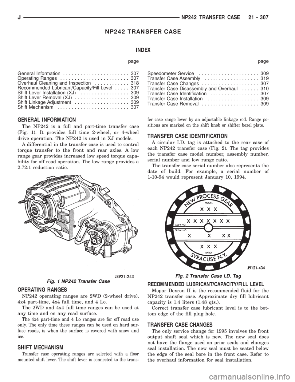
The NP242 is a full and part-time transfer case
(Fig. 1). It provides full time 2-wheel, or 4-wheel
drive operation. The NP242 is used in XJ models.
A differential in the transfer case is used to control
torque transfer to the front and rear axles. A low
range gear provides increased low speed torque capa-
bility for off road operation. The low range provides a
2.72:1 reduction ratio.
OPERATING RANGES
NP242 operating ranges are 2WD (2-wheel drive),
4x4 part-time, 4x4 full time, and 4 Lo.
The 2WD and 4x4 full time ranges can be used at
any time and on any road surface.
The 4x4 part-time and 4 Lo ranges are for off road use
only. The only time these ranges can be used on hard sur-
face roads, is when the surface is covered with snow and
ice.
SHIFT MECHANISM
Transfer case operating ranges are selected with a floor
mounted shift lever. The shift lever is connected to the trans-fer case range lever by an adjustable linkage rod. Range po-
sitions are marked on the shift knob or shifter bezel plate.
TRANSFER CASE IDENTIFICATION
A circular I.D. tag is attached to the rear case of
each NP242 transfer case (Fig. 2). The tag provides
the transfer case model number, assembly number,
serial number and low range ratio.
The transfer case serial number also represents the
date of build. For example, a serial number of
1-10-94 would represent January 10, 1994.
RECOMMENDED LUBRICANT/CAPACITY/FILL LEVEL
Mopar Dexron II is the recommended fluid for the
NP242 transfer case. Approximate dry fill lubricant
capacity is 1.4 liters (1.48 qts.).
Correct transfer case lubricant level is to the bot-
tom edge of the fill plug hole.
TRANSFER CASE CHANGES
The only service change for 1995 involves the front
output shaft seal which is new. The new seal does
not have the flange used on prior seals and changes
seal installation. The new seal must be seated below
the edge of the seal bore in the front case. Refer to
the overhaul information for seal installation.
Fig. 1 NP242 Transfer Case
Fig. 2 Transfer Case I.D. Tag
JNP242 TRANSFER CASE 21 - 307
Page 1877 of 2158
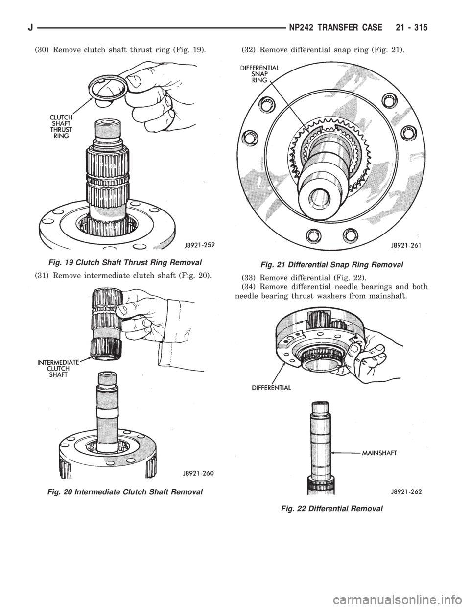
(30) Remove clutch shaft thrust ring (Fig. 19).
(31) Remove intermediate clutch shaft (Fig. 20).(32) Remove differential snap ring (Fig. 21).
(33) Remove differential (Fig. 22).
(34) Remove differential needle bearings and both
needle bearing thrust washers from mainshaft.
Fig. 19 Clutch Shaft Thrust Ring Removal
Fig. 20 Intermediate Clutch Shaft Removal
Fig. 21 Differential Snap Ring Removal
Fig. 22 Differential Removal
JNP242 TRANSFER CASE 21 - 315