1995 JEEP XJ ignition lock
[x] Cancel search: ignition lockPage 30 of 2158
²Do not allow passengers to ride in a vehicle being
towed.
²Always observe state and local laws regarding tow-
ing regulations.²Do not tow a vehicle in a manner that could jeop-
ardize the safety of the operator, pedestrians or other
motorists.
²Do not attach tow chains, T-hooks, J-hooks, or a
tow sling to a bumper, steering linkage, drive shafts
or a non-reinforced frame hole.
GROUND CLEARANCE AND RAMP ANGLE
GROUND CLEARANCE
CAUTION: If vehicle is towed with wheels removed,
install lug nuts to retain brake drums.
A towed vehicle should be raised until lifted wheels
are a minimum 100 mm (4 in) from the ground. Be
sure there is adequate ground clearance at the oppo-
site end of the vehicle, especially when towing over
rough terrain or steep rises in the road. If necessary,
remove the wheels from the lifted end of the vehicle
and lower the vehicle closer to the ground, to in-
crease the ground clearance at the opposite end of
the vehicle. Install lug nuts on wheel attaching studs
to retain brake drums.
FLAT-BED TOWING RAMP ANGLE
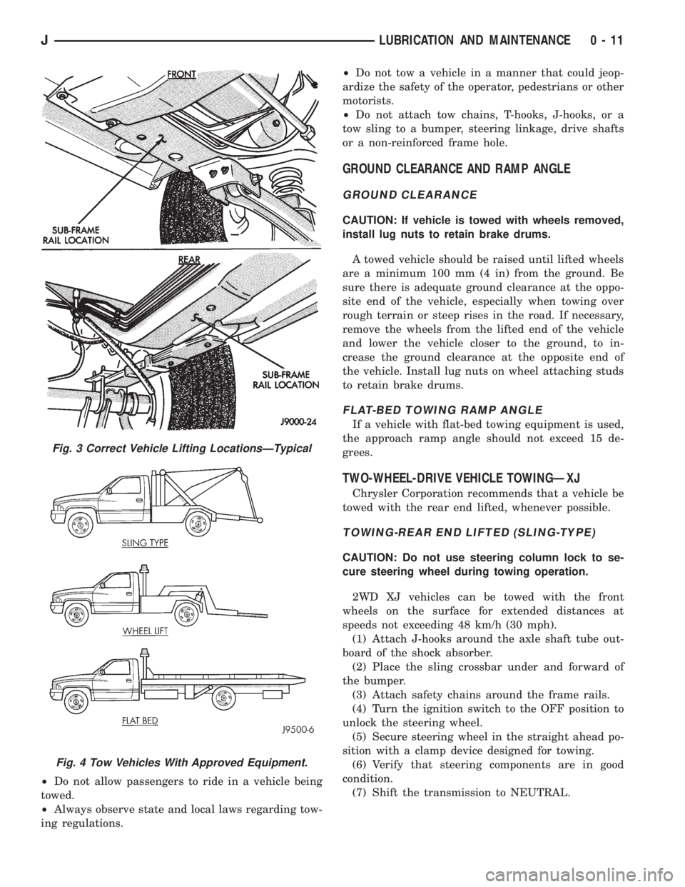
If a vehicle with flat-bed towing equipment is used,
the approach ramp angle should not exceed 15 de-
grees.
TWO-WHEEL-DRIVE VEHICLE TOWINGÐXJ
Chrysler Corporation recommends that a vehicle be
towed with the rear end lifted, whenever possible.
TOWING-REAR END LIFTED (SLING-TYPE)
CAUTION: Do not use steering column lock to se-
cure steering wheel during towing operation.
2WD XJ vehicles can be towed with the front
wheels on the surface for extended distances at
speeds not exceeding 48 km/h (30 mph).
(1) Attach J-hooks around the axle shaft tube out-
board of the shock absorber.
(2) Place the sling crossbar under and forward of
the bumper.
(3) Attach safety chains around the frame rails.
(4) Turn the ignition switch to the OFF position to
unlock the steering wheel.
(5) Secure steering wheel in the straight ahead po-
sition with a clamp device designed for towing.
(6) Verify that steering components are in good
condition.
(7) Shift the transmission to NEUTRAL.
Fig. 3 Correct Vehicle Lifting LocationsÐTypical
Fig. 4 Tow Vehicles With Approved Equipment.
JLUBRICATION AND MAINTENANCE 0 - 11
Page 31 of 2158
TOWING-FRONT END LIFTED (SLING-TYPE)
CAUTION: Many vehicles are equipped with air
dams, spoilers, and/or ground effect panels. To
avoid component damage, a wheel-lift towing vehi-
cle or a flat-bed hauling vehicle is recommended.
If a 2WD XJ vehicle cannot be towed with the rear
wheels lifted, it can be towed with the front wheels
lifted.
(1) Attach a J-hook to the disabled vehicle at the
left side of the axle.
(2) Position the sling crossbar close to the J-hook
and below the front bumper.
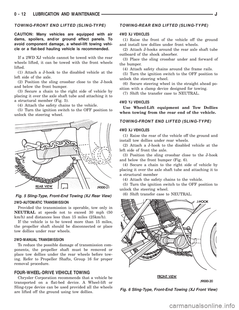
(3) Secure a chain to the right side of vehicle by
placing it over the axle shaft tube and attaching it to
a structural member (Fig. 5).
(4) Attach the safety chains to the vehicle.
(5) Turn the ignition switch to the OFF position to
unlock the steering wheel.
2WD-AUTOMATIC TRANSMISSION
Provided the transmission is operable, tow only in
NEUTRALat speeds not to exceed 30 mph (50
km/h) and distances less than 15 miles (25km/h).
If the vehicle is to be towed more than 15 miles,
the propeller shaft should be disconnected or place
tow dollies under rear wheels.
2WD-MANUAL TRANSMISSION
To reduce the possible damage of transmission com-
ponents, the propeller shaft must be removed or
place tow dollies under the rear wheels before tow-
ing. Refer to Propeller Shafts, Group 16 for proper
removal procedure.
FOUR-WHEEL-DRIVE VEHICLE TOWING
Chrysler Corporation recommends that a vehicle be
transported on a flat-bed device. A Wheel-lift or
Sling-type device can be used provided all the wheels
are lifted off the ground using tow dollies.
TOWING-REAR END LIFTED (SLING-TYPE)
4WD XJ VEHICLES
(1) Raise the front of the vehicle off the ground
and install tow dollies under front wheels.
(2) Attach J-hooks around the rear axle shaft tube
outboard of the shock absorber.
(3) Place the sling crossbar under and forward of
the bumper.
(4) Attach safety chains around the frame rails.
(5) Turn the ignition switch to the OFF position to
unlock the steering wheel.
(6) Secure steering wheel in the straight ahead po-
sition with a clamp device designed for towing.
(7) Shift the transfer case to NEUTRAL.
4WD YJ VEHICLES
Use Wheel-Lift equipment and Tow Dollies
when towing from the rear end of the vehicle.
TOWING-FRONT END LIFTED (SLING-TYPE)
4WD XJ VEHICLES
(1) Raise the rear of the vehicle off the ground and
install tow dollies under rear wheels.
(2) Attach a J-hook to the disabled vehicle at the
left side of front the axle.
(3) Position the sling crossbar close to the J-hook
and below the front bumper (Fig. 6).
(4) Secure a chain to the right side of vehicle by
placing it over the axle shaft tube and attaching it to
a structural member
(4) Attach the safety chains to the vehicle.
(5) Turn the ignition switch to the OFF position to
unlock the steering wheel.
(6) Shift transfer case to NEUTRAL.
Fig. 5 Sling-Type, Front-End Towing (XJ Rear View)
Fig. 6 Sling-Type, Front-End Towing (XJ Front View)
0 - 12 LUBRICATION AND MAINTENANCEJ
Page 32 of 2158
4WD YJ VEHICLES
(1) Raise the rear of the vehicle off the ground and
install tow dollies under rear wheels.
CAUTION: Use tow chains with T-hooks for con-
necting to the disabled vehicle's frame rails. Never
use J-hooks.
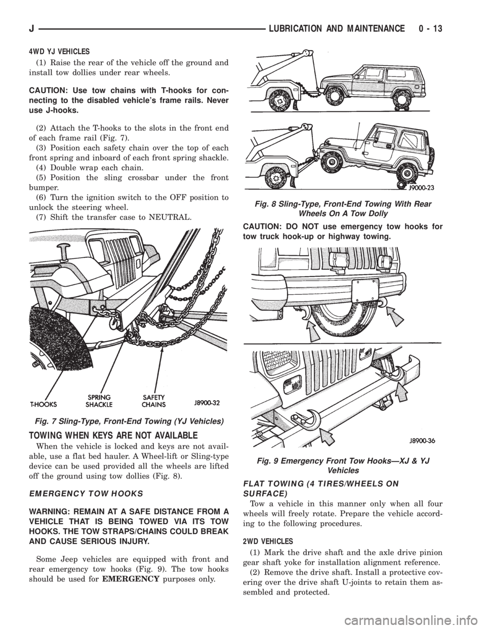
(2) Attach the T-hooks to the slots in the front end
of each frame rail (Fig. 7).
(3) Position each safety chain over the top of each
front spring and inboard of each front spring shackle.
(4) Double wrap each chain.
(5) Position the sling crossbar under the front
bumper.
(6) Turn the ignition switch to the OFF position to
unlock the steering wheel.
(7) Shift the transfer case to NEUTRAL.
TOWING WHEN KEYS ARE NOT AVAILABLE
When the vehicle is locked and keys are not avail-
able, use a flat bed hauler. A Wheel-lift or Sling-type
device can be used provided all the wheels are lifted
off the ground using tow dollies (Fig. 8).
EMERGENCY TOW HOOKS
WARNING: REMAIN AT A SAFE DISTANCE FROM A
VEHICLE THAT IS BEING TOWED VIA ITS TOW
HOOKS. THE TOW STRAPS/CHAINS COULD BREAK
AND CAUSE SERIOUS INJURY.
Some Jeep vehicles are equipped with front and
rear emergency tow hooks (Fig. 9). The tow hooks
should be used forEMERGENCYpurposes only.CAUTION: DO NOT use emergency tow hooks for
tow truck hook-up or highway towing.
FLAT TOWING (4 TIRES/WHEELS ON
SURFACE)
Tow a vehicle in this manner only when all four
wheels will freely rotate. Prepare the vehicle accord-
ing to the following procedures.
2WD VEHICLES
(1) Mark the drive shaft and the axle drive pinion
gear shaft yoke for installation alignment reference.
(2) Remove the drive shaft. Install a protective cov-
ering over the drive shaft U-joints to retain them as-
sembled and protected.
Fig. 7 Sling-Type, Front-End Towing (YJ Vehicles)
Fig. 8 Sling-Type, Front-End Towing With Rear
Wheels On A Tow Dolly
Fig. 9 Emergency Front Tow HooksÐXJ & YJ
Vehicles
JLUBRICATION AND MAINTENANCE 0 - 13
Page 33 of 2158
(3) Cover the open end of the transmission exten-
sion housing.
4WD VEHICLESÐXJ
(1) Shift transfer case lever to NEUTRAL.
(2) Place ignition switch in the unlocked position.
4WD VEHICLESÐYJ
CAUTION: Follow these steps to be certain that the
transfer case is fully in N (NEUTRAL) and that the
axle is completely disengaged before flat towing to
prevent damage to internal parts.
(1) Shift transfer case into 2H and check that the
4WD light goes out.
(2) Start engine and drive the vehicle 3 mm (10 ft.)
rearward and then 3 mm (10 ft.) forward to make
sure the axle is disengaged.(3) Shift transmission to Neutral.
(4) Turn off engine with the ignition key in the un-
locked OFF position.
(5) Shift transfer case lever from 2H to N (NEU-
TRAL) position.
(6) Shift manual transmission into gear or auto-
matic transmission into P (PARK).
WARNING: WITH THE TRANSFER CASE IN NEU-
TRAL POSITION, THE VEHICLE COULD ROLL UN-
EXPECTEDLY. THE PARKING BRAKE SHOULD
ALWAYS BE APPLIED BEFORE THE TOW BAR IS
ATTACHED.
(7) Attach vehicle to the tow vehicle with tow bar.
CAUTION: Do not use a bumper mounted clamp-on
tow bar, damage to bumper face bar may occur.
0 - 14 LUBRICATION AND MAINTENANCEJ
Page 50 of 2158

(5) Inspect the reservoir rubber diaphragm seal for
cracks, cuts and distortion.
(6) Inspect the brake fluid tubing fittings and the
master cylinder housing for indications of fluid leak-
age. Repair as necessary.
(7) Install the brake fluid reservoir cover.
ANTI-LOCK BRAKE SYSTEMÐXJ VEHICLES
The anti-lock brake system fluid reservoir for XJ
Vehicles is located in the engine compartment at the
left side of the dash panel.
(1) Turn the ignition switch ON and allow the
pump motor to operate until it automatically de-en-
ergizes.
(2) Clean the cover before removing it.
CAUTION: Over-filling could cause fluid overflow
and possible reservoir damage when the pump mo-
tor energizes.
(3) The brake fluid level should be no lower than
the ADD indicator on the side of the reservoir (Fig.
8). If not, add brake fluid as necessary. Raise the
fluid level to the FULL indicator only. Do not over-fill
the reservoir.
(4) Turn the ignition switch OFF.
BRAKE SYSTEM INSPECTION
A brake system inspection should be included with
all brake service procedures, and also each time the
vehicle is lubricated.
(1) Inspect the brake pads and linings for excessive
wear, cracks, charred surfaces and broken rivets.
(2) Inspect brake pads and linings for contamina-
tion from brake fluid, and/or other fluids.
(3) Replace the brake pads linings if they are worn
to within 0.78 mm (1/32 in) of the rivet head.
(4) Operate the rear brake self-adjuster lever and
pivot. Test the operation of the self-adjuster screw for
ease of movement.
(5) Inspect the self-adjuster components for wear
or damage.
(6) Inspect the disc brake caliper dust boot for
damage and indications of brake fluid leakage. In-
spect the bushings and pins for corrosion, tears and a
binding condition.
(7) Pull the rear wheel cylinder dust boot back to
expose the wheel cylinder housing. Inspect for fluid
leaks. Inspect the pistons and cylinder bores.
(8) Inspect the brake differential warning valve
and housing for indications of leakage.
BRAKE FLUID HOSES/TUBING
The rubber brake fluid hoses should be inspected
for:
²Correct length
²Severe surface cracking
²Swelling
²Pulling
²Scuffing
²Excessively worn areas
If the hose has cracks or abrasions in the rub-
ber cover, the hose should be replaced.
(1) Inspect all the hoses for kinks, a distorted con-
dition and fluid leakage.
(2) Inspect the hose and tubing routing under the
vehicle. Verify that no hose/tubing is rubbing against
any exhaust or other underbody components.
PARKING BRAKE
(1) Engage the parking brake pedal and then re-
lease it.
(2) Test it for smooth operation and vehicle-holding
capability.
(3) Inspect the parking brake cables.
(4) With the parking brake released, the rear
wheels should
rotate without restriction. Adjust the parking brake
cable tension, if necessary (Fig. 9 and 10).
(5) Repair any parking brake malfunctions.
BRAKE OPERATIONAL TEST
(1) Drive the vehicle and test for proper brake ac-
tion.
Fig. 7 Reservoir Fluid LevelÐYJ (2.5L)
Fig. 8 Reservoir Fluid LevelÐYJ-XJ and Anti-Lock
Brake System
JLUBRICATION AND MAINTENANCE 0 - 31
Page 185 of 2158

ABS OPERATION AND SERVICE
INDEX
page page
ABS Component Serviceability............... 37
ABS Diagnostic Connector.................. 35
ABS Operation in Antilock Braking Mode........ 36
ABS Operation in Normal Braking Mode........ 35
ABS System Power-Up and Initialization........ 35
Acceleration Switch........................ 35
Acceleration Switch Installation............... 39
Acceleration Switch Operation................ 37
Acceleration Switch Removal................ 39
Combination Valve........................ 34
ECU Installation (XJ Models)................. 40
ECU Operation........................... 37
ECU Removal (XJ Models).................. 40
ECU Removal/Installation (YJ Models).......... 41
Electronic Control Unit (ECU)................ 34
Front Wheel Sensor Installation............... 38
Front Wheel Sensor Removal................ 38HCU Installation (XJ)....................... 43
HCU Installation (YJ)....................... 44
HCU Operation........................... 36
HCU Removal (XJ)........................ 41
HCU Removal (YJ)........................ 44
Hydraulic Control Unit (HCU)................. 33
Ignition Switch........................... 35
Master Cylinder/Power Brake Booster.......... 34
Rear Wheel Sensor Installation and Adjustment . . . 38
Rear Wheel Sensor Removal................ 38
Speed Sensor Air Gap..................... 37
System Description........................ 33
System Relays........................... 35
System Warning Light...................... 35
Wheel Speed Sensor Operation.............. 37
Wheel Speed Sensors..................... 34
SYSTEM DESCRIPTION
The Jeep antilock brake system (ABS) is an elec-
tronically operated, all wheel brake control system.
The system is designed to prevent wheel lockup
and maintain steering control during periods of high
wheel slip when braking. Preventing lockup is accom-
plished by modulating fluid pressure to the wheel
brake units.
The hydraulic system is a three channel design.
The front wheel brakes are controlled individually
and the rear wheel brakes in tandem (Fig. 1). The
ABS electrical system is separate from other electri-
cal circuits in the vehicle. A specially programmed
electronic control unit (ECU) operates the system
components.
ABS system major components include:
²hydraulic control unit (HCU)
²electronic control unit (ECU)
²wheel speed sensors and axle shaft tone rings
²acceleration switch
²main relay and pump motor relay
²ABS warning light
²pump motor sensor
HYDRAULIC CONTROL UNIT (HCU)
The hydraulic control unit (HCU) consists of a
valve body, pump body, accumulators, pump motor,
and wire harnesses (Fig. 2).
The pump, motor, and accumulators are combined
into an assembly attached to the valve body. The ac-
cumulators store the extra fluid released to the sys-
tem for ABS mode operation. The pump provides the
fluid volume needed and is operated by a DC type
motor. The motor is controlled by the ECU.The valve body contains the solenoid valves. The
valves modulate brake pressure during antilock brak-
ing and are controlled by the ECU.
The HCU provides three channel pressure control
to the front and rear brakes. One channel controls
the rear wheel brakes in tandem. The two remaining
channels control the front wheel brakes individually.
During antilock braking, the solenoid valves are
opened and closed as needed. The valves are not static.
They are cycled rapidly and continuously to modulate
pressure and control wheel slip and deceleration.
Fig. 1 Jeep ABS System
JABS OPERATION AND SERVICE 5 - 33
Page 186 of 2158

MASTER CYLINDER/POWER BRAKE BOOSTER
A 25 mm bore master cylinder and 205 mm (8.07
in.) dual diaphragm power brake booster are used for
all ABS applications (Fig. 2).
The master cylinder has a removable plastic reser-
voir which is the only serviceable component. The
cylinder body and pistons are not repairable and are
serviced as an assembly. The check valve and grom-
met are the only serviceable parts on the booster.
The booster itself is only serviced as an assembly.
COMBINATION VALVE
A combination valve is used with the ABS system
(Fig. 2). The valve contains a front/rear brake pres-
sure differential switch and rear brake proportioning
valve. The combination valve is connected between
the master cylinder and HCU.
The pressure differential switch is connected to the
red brake warning light. The switch is actuated by
movement of the switch valve. The switch monitors
fluid pressure in the separate front/rear brake hy-
draulic circuits.
A decrease or loss of fluid pressure in either hy-
draulic circuit will cause the switch valve to shuttle
forward or rearward in response to the pressure dif-
ferential. Movement of the switch valve will push the
switch plunger upward. This closes the switch inter-
nal contacts completing the electrical circuit to the
red warning light. The switch valve remains in an
actuated position until the fault is repaired.
The rear proportioning valve is used to balance front-
rear brake action.
ELECTRONIC CONTROL UNIT (ECU)
A separate electronic control unit (ECU) operates
the ABS system (Fig. 3). The ECU is separate from
other vehicle electrical circuits. ECU voltage source
is through the ignition switch in the Run position.The ECU is located under the instrument panel in
the passenger compartment. On YJ models, it is just
above the heater plenum in line with the glove box.
In left hand drive XJ models, it at the right side of
the steering column. In right hand drive models, it is
near the cowl panel
The ECU contains dual microprocessors. A logic
block in each microprocessor receives identical sensor
signals. These signals are processed and compared si-
multaneously.
The ECU contains a self check program that illu-
minates the ABS warning light when a system fault
is detected. Faults are stored in a diagnostic program
memory and are accessible with the DRB scan tool.
ABS faults remain in memory until cleared, or un-
til after the vehicle is started approximately 50
times. Stored faults arenoterased if the battery is
disconnected.
WHEEL SPEED SENSORS
A speed sensor is used at each wheel. The sensors
convert wheel speed into an electrical signal. This
signal is transmitted to the antilock ECU.
A gear type tone ring serves as the trigger mecha-
nism for each sensor. The tone rings are mounted at
the outboard ends of the front and rear axle shafts.
Different sensors are used at the front and rear
wheels (Fig. 4). The front/rear sensors have the same
electrical values but are not interchangeable.
Fig. 2 ABS Master Cylinder-Booster-Combination
Valve-HCU
Fig. 3 Antilock ECU
5 - 34 ABS OPERATION AND SERVICEJ
Page 187 of 2158

ABS DIAGNOSTIC CONNECTOR
The ABS diagnostic connector is inside the vehicle.
The connector is the access point for the DRB scan
tool.
On XJ models, the connector is located under the
instrument panel to the right of the steering column.
On some models, the connecter may be tucked under
the carpeting on the transmission tunnel. The con-
necter is a black, 6-way type.
On YJ models, the connector is under the instru-
ment panel by the the driver side kick panel. The
connecter is a black, 6 or 8-way type.
The DRB scan tool kit contains adapter cords for
both types of connecter. Use the appropriate cord for
test hookup.
ACCELERATION SWITCH
An acceleration switch (Fig. 5), provides an addi-
tional vehicle deceleration reference during 4-wheel
drive operation. The switch is monitored by the an-
tilock ECU at all times. The switch reference signal
is utilized by the ECU when all wheels are deceler-
ating at the same speed.
SYSTEM RELAYS
The ABS system has two relays, which are the
main and motor pump relays. The motor pump relay
is used for the motor pump only. The main relay is
used for the solenoid valves and ECU. The main re-
lay is connected to the ECU at the power control re-
lay terminal. The pump motor relay starts/stops the
pump motor when signaled by the ECU.
IGNITION SWITCH
The antilock ECU and warning light are in standby
mode with the ignition switch in Off or Accessory po-
sition. No operating voltage is supplied to the system
components.A 12 volt power feed is supplied to the ECU and
warning light when the ignition switch is in the Run
position.
SYSTEM WARNING LIGHT
The amber ABS warning light is in circuit with the
ECU and operates independently of the red brake
warning light.
The ABS light indicates antilock system condition.
The light illuminates (flashes) at start-up for the self
check. The light goes out when the self check pro-
gram determines system operation is normal.
ABS SYSTEM POWER-UP AND INITIALIZATION
battery voltage is supplied to the ECU ignition ter-
minal when the ignition switch is turned to Run po-
sition. The ECU performs a system initialization
procedure at this point. Initialization consists of a
static and dynamic self check of system electrical
components.
The static check occurs after the ignition switch is
turned to Run position. The dynamic check occurs
when vehicle road speed reaches approximately 10
kph (6 mph). During the dynamic check, the ECU
briefly cycles the pump and solenoids to verify oper-
ation.
If an ABS component exhibits a fault during initial-
ization, the ECU illuminates the amber warning
light and registers a fault code in the microprocessor
memory.
ABS OPERATION IN NORMAL BRAKING MODE
The ECU monitors wheel speed sensor inputs con-
tinuously while the vehicle is in motion. However,
the ECU will not activate any ABS components as
long as sensor inputs and the acceleration switch in-
dicate normal braking.
Fig. 4 Wheel Speed SensorsFig. 5 Acceleration Switch
JABS OPERATION AND SERVICE 5 - 35