1995 JEEP XJ wheel torque
[x] Cancel search: wheel torquePage 1442 of 2158
plugged catalytic convertor.
(27) If equipped with automatic transmission, ver-
ify that electrical harness is firmly connected to park/
neutral safety switch. Refer to Automatic
Transmission section of Group 21.
(28) Verify that the harness connector is firmly
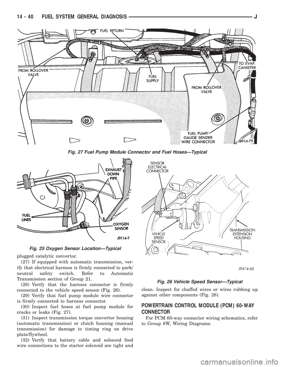
connected to the vehicle speed sensor (Fig. 26).
(29) Verify that fuel pump module wire connector
is firmly connected to harness connector.
(30) Inspect fuel hoses at fuel pump module for
cracks or leaks (Fig. 27).
(31) Inspect transmission torque convertor housing
(automatic transmission) or clutch housing (manual
transmission) for damage to timing ring on drive
plate/flywheel.
(32) Verify that battery cable and solenoid feed
wire connections to the starter solenoid are tight andclean. Inspect for chaffed wires or wires rubbing up
against other components (Fig. 28).
POWERTRAIN CONTROL MODULE (PCM) 60-WAY
CONNECTOR
For PCM 60-way connector wiring schematics, refer
to Group 8W, Wiring Diagrams.
Fig. 27 Fuel Pump Module Connector and Fuel HosesÐTypical
Fig. 25 Oxygen Sensor LocationÐTypical
Fig. 26 Vehicle Speed SensorÐTypical
14 - 40 FUEL SYSTEM GENERAL DIAGNOSISJ
Page 1472 of 2158
SERVICE DIAGNOSIS
INDEX
page page
Runout.................................. 4
Unbalance............................... 3Universal Joint Angle Measurement............. 4
Vibration................................. 3
VIBRATION
Tires that are out-of-round or wheels that are un-
balanced will cause a low frequency vibration. Refer
to Group 22, Wheels and Tires for additional infor-
mation.
Brake drums that are unbalanced will cause a
harsh, low frequency vibration. Refer to Group 5,
Brakes for additional information.
Driveline vibration can also result from loose or
damaged engine mounts. Refer to Group 21, Trans-
missions for additional information.
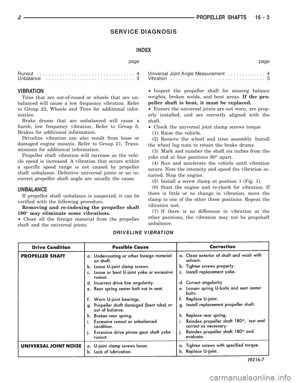
Propeller shaft vibration will increase as the vehi-
cle speed is increased. A vibration that occurs within
a specific speed range is not caused by propeller
shaft unbalance. Defective universal joints or an in-
correct propeller shaft angle are usually the cause.
UNBALANCE
If propeller shaft unbalance is suspected, it can be
verified with the following procedure.
Removing and re-indexing the propeller shaft
180É may eliminate some vibrations.
²Clean all the foreign material from the propeller
shaft and the universal joints.²Inspect the propeller shaft for missing balance
weights, broken welds, and bent areas.If the pro-
peller shaft is bent, it must be replaced.
²Ensure the universal joints are not worn, are prop-
erly installed, and are correctly aligned with the
shaft.
²Check the universal joint clamp screws torque
(1) Raise the vehicle.
(2) Remove the wheel and tires assembly. Install
the wheel lug nuts to retain the brake drums.
(3) Mark and number the shaft six inches from the
yoke end at four positions 90É apart.
(4) Run and accelerate the vehicle until vibration
occurs. Note the intensity and speed the vibration oc-
curred. Stop the engine.
(5) Install a screw clamp at position 1 (Fig. 1).
(6) Start the engine and re-check for vibration. If
there is little or no change in vibration, move the
clamp to one of the other three positions. Repeat the
vibration test.
(7) If there is no difference in vibration at the
other positions, the vibration may not be propshaft
unbalance.
DRIVELINE VIBRATION
JPROPELLER SHAFTS 16 - 3
Page 1474 of 2158
²Have at least a 1/2 degree continuous operating
(propeller shaft) angle
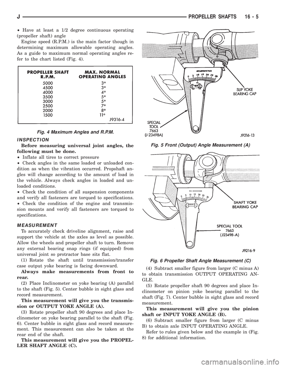
Engine speed (R.P.M.) is the main factor though in
determining maximum allowable operating angles.
As a guide to maximum normal operating angles re-
fer to the chart listed (Fig. 4).
INSPECTION
Before measuring universal joint angles, the
following must be done.
²Inflate all tires to correct pressure
²Check angles in the same loaded or unloaded con-
dition as when the vibration occurred. Propshaft an-
gles will change according to the amount of load in
the vehicle. Always check angles in loaded and un-
loaded conditions.
²Check the condition of all suspension components
and verify all fasteners are torqued to specifications.
²Check the condition of the engine and transmis-
sion mounts and verify all fasteners are torqued to
specifications.
MEASUREMENT
To accurately check driveline alignment, raise and
support the vehicle at the axles as level as possible.
Allow the wheels and propeller shaft to turn. Remove
any external bearing snap rings (if equipped) from
universal joint so protractor base sits flat.
(1) Rotate the shaft until transmission/transfer
case output yoke bearing is facing downward.
Always make measurements from front to
rear.
(2) Place Inclinometer on yoke bearing (A) parallel
to the shaft (Fig. 5). Center bubble in sight glass and
record measurement.
This measurement will give you the transmis-
sion or OUTPUT YOKE ANGLE (A).
(3) Rotate propeller shaft 90 degrees and place In-
clinometer on yoke bearing parallel to the shaft (Fig.
6). Center bubble in sight glass and record measure-
ment. This measurement can also be taken at the
rear end of the shaft.
This measurement will give you the PROPEL-
LER SHAFT ANGLE (C).(4) Subtract smaller figure from larger (C minus A)
to obtain transmission OUTPUT OPERATING AN-
GLE.
(5) Rotate propeller shaft 90 degrees and place In-
clinometer on pinion yoke bearing parallel to the
shaft (Fig. 7). Center bubble in sight glass and record
measurement.
This measurement will give you the pinion
shaft or INPUT YOKE ANGLE (B).
(6) Subtract smaller figure from larger (C minus
B) to obtain axle INPUT OPERATING ANGLE.
Refer to rules given below and the example in (Fig.
8) for additional information.
Fig. 4 Maximum Angles and R.P.M.
Fig. 5 Front (Output) Angle Measurement (A)
Fig. 6 Propeller Shaft Angle Measurement (C)
JPROPELLER SHAFTS 16 - 5
Page 1485 of 2158
STEERING
CONTENTS
page page
GENERAL INFORMATION.................. 1
GENERAL INFORMATION................. 48
MANUAL STEERING GEAR................ 37
POWER STEERING PUMP................. 11
POWER STEERING SYSTEM DIAGNOSIS...... 3
RECIRCULATING BALL POWER STEERING
GEAR............................... 21STEERING COLUMN GENERAL SERVICEÐXJ . 47
STEERING COLUMNÐYJ................. 58
STEERING LINKAGEÐXJ................. 16
STEERING LINKAGEÐYJ................. 19
STEERING RHD......................... 74
TORQUE SPECIFICATIONS................ 78
GENERAL INFORMATION
STEERING SYSTEM COMPONENTS
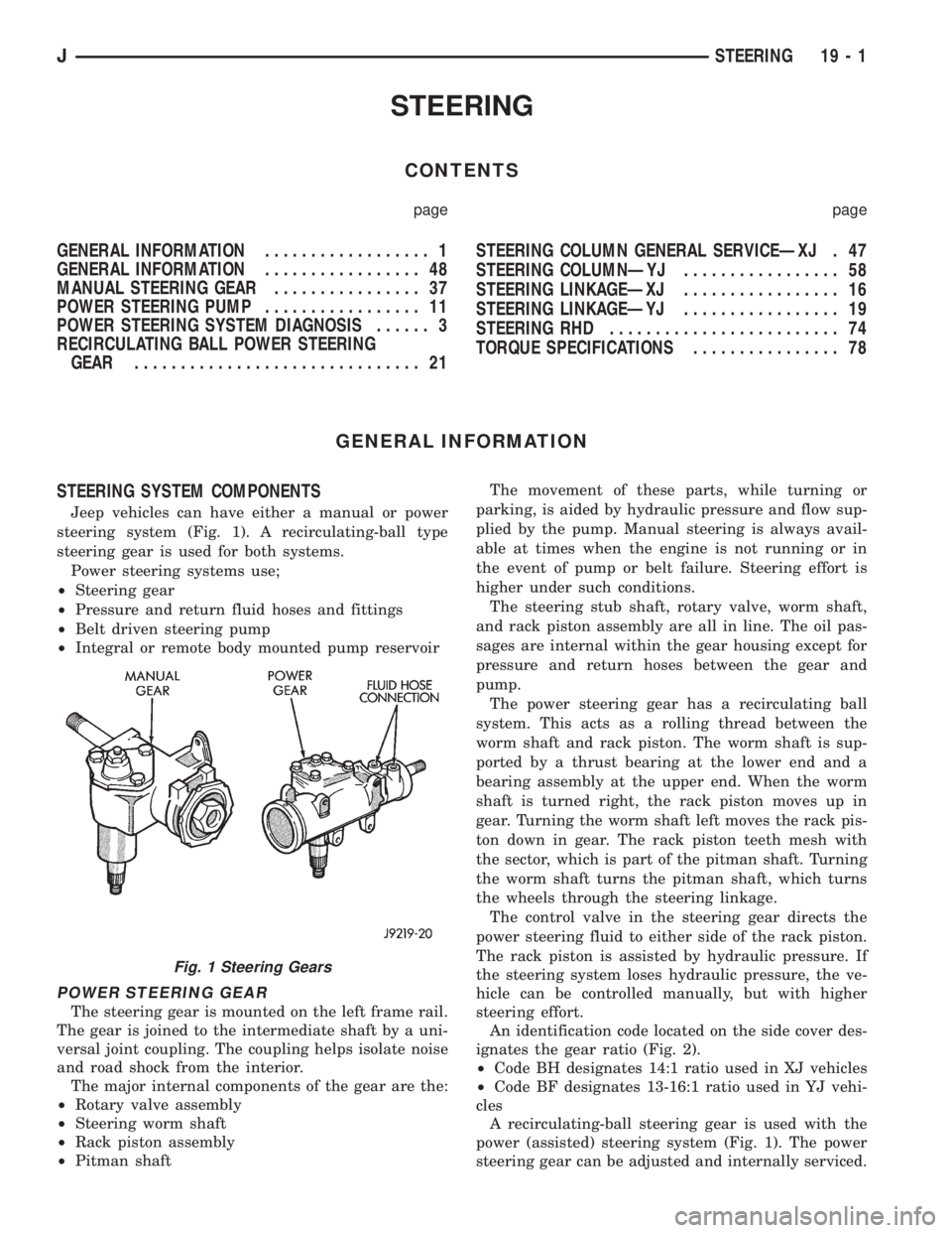
Jeep vehicles can have either a manual or power
steering system (Fig. 1). A recirculating-ball type
steering gear is used for both systems.
Power steering systems use;
²Steering gear
²Pressure and return fluid hoses and fittings
²Belt driven steering pump
²Integral or remote body mounted pump reservoir
POWER STEERING GEAR
The steering gear is mounted on the left frame rail.
The gear is joined to the intermediate shaft by a uni-
versal joint coupling. The coupling helps isolate noise
and road shock from the interior.
The major internal components of the gear are the:
²Rotary valve assembly
²Steering worm shaft
²Rack piston assembly
²Pitman shaftThe movement of these parts, while turning or
parking, is aided by hydraulic pressure and flow sup-
plied by the pump. Manual steering is always avail-
able at times when the engine is not running or in
the event of pump or belt failure. Steering effort is
higher under such conditions.
The steering stub shaft, rotary valve, worm shaft,
and rack piston assembly are all in line. The oil pas-
sages are internal within the gear housing except for
pressure and return hoses between the gear and
pump.
The power steering gear has a recirculating ball
system. This acts as a rolling thread between the
worm shaft and rack piston. The worm shaft is sup-
ported by a thrust bearing at the lower end and a
bearing assembly at the upper end. When the worm
shaft is turned right, the rack piston moves up in
gear. Turning the worm shaft left moves the rack pis-
ton down in gear. The rack piston teeth mesh with
the sector, which is part of the pitman shaft. Turning
the worm shaft turns the pitman shaft, which turns
the wheels through the steering linkage.
The control valve in the steering gear directs the
power steering fluid to either side of the rack piston.
The rack piston is assisted by hydraulic pressure. If
the steering system loses hydraulic pressure, the ve-
hicle can be controlled manually, but with higher
steering effort.
An identification code located on the side cover des-
ignates the gear ratio (Fig. 2).
²Code BH designates 14:1 ratio used in XJ vehicles
²Code BF designates 13-16:1 ratio used in YJ vehi-
cles
A recirculating-ball steering gear is used with the
power (assisted) steering system (Fig. 1). The power
steering gear can be adjusted and internally serviced.
Fig. 1 Steering Gears
JSTEERING 19 - 1
Page 1499 of 2158
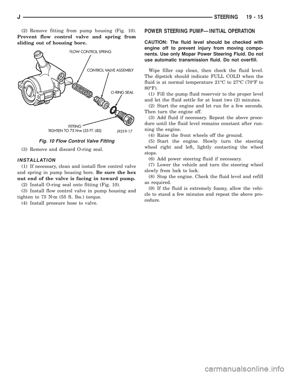
(2) Remove fitting from pump housing (Fig. 10).
Prevent flow control valve and spring from
sliding out of housing bore.
(3) Remove and discard O-ring seal.
INSTALLATION
(1) If necessary, clean and install flow control valve
and spring in pump housing bore.Be sure the hex
nut end of the valve is facing in toward pump.
(2) Install O-ring seal onto fitting (Fig. 10).
(3) Install flow control valve in pump housing and
tighten to 75 Nzm (55 ft. lbs.) torque.
(4) Install pressure hose to valve.
POWER STEERING PUMPÐINITIAL OPERATION
CAUTION: The fluid level should be checked with
engine off to prevent injury from moving compo-
nents. Use only Mopar Power Steering Fluid. Do not
use automatic transmission fluid. Do not overfill.
Wipe filler cap clean, then check the fluid level.
The dipstick should indicate FULL COLD when the
fluid is at normal temperature 21ÉC to 27ÉC (70ÉF to
80ÉF).
(1) Fill the pump fluid reservoir to the proper level
and let the fluid settle for at least two (2) minutes.
(2) Start the engine and let run for a few seconds.
Then turn the engine off.
(3) Add fluid if necessary. Repeat the above proce-
dure until the fluid level remains constant after run-
ning the engine.
(4) Raise the front wheels off the ground.
(5) Start the engine. Slowly turn the steering
wheel right and left, lightly contacting the wheel
stops.
(6) Add power steering fluid if necessary.
(7) Lower the vehicle and turn the steering wheel
slowly from lock to lock.
(8) Stop the engine. Check the fluid level and refill
as required.
(9) If the fluid is extremely foamy, allow the vehi-
cle to stand a few minutes and repeat the above pro-
cedure.
Fig. 10 Flow Control Valve Fitting
JSTEERING 19 - 15
Page 1500 of 2158
STEERING LINKAGEÐXJ
INDEX
page page
Drag Link............................... 16
Pitman Arm.............................. 17
Service Information........................ 16Steering Damper.......................... 17
TieRod ................................ 16
SERVICE INFORMATION
The steering linkage consists of a pitman arm, drag
link, tie rod, and steering damper. Adjustment
sleeves are used on the tie rod and drag link for toe
and steering wheel alignment.
Refer to Group 2, Front Suspension and Axle for
additional information.
The tie-rod end ball stud seals should be inspected
during all oil changes.
A damaged ball stud seal requires removal of the
seal. Inspect the tie-rod end ball stud at the throat
opening. Check for lubricant loss, contamination, ball
stud wear or corrosion. If these conditions exist, re-
place the tie-rod. A replacement seal can be installed
if lubricant is in good condition. Otherwise, a com-
plete replacement ball stud end should be installed.
Lubricate the tie-rod end with MOPARtMulti-Mile-
age Lubricant, or equivalent product.
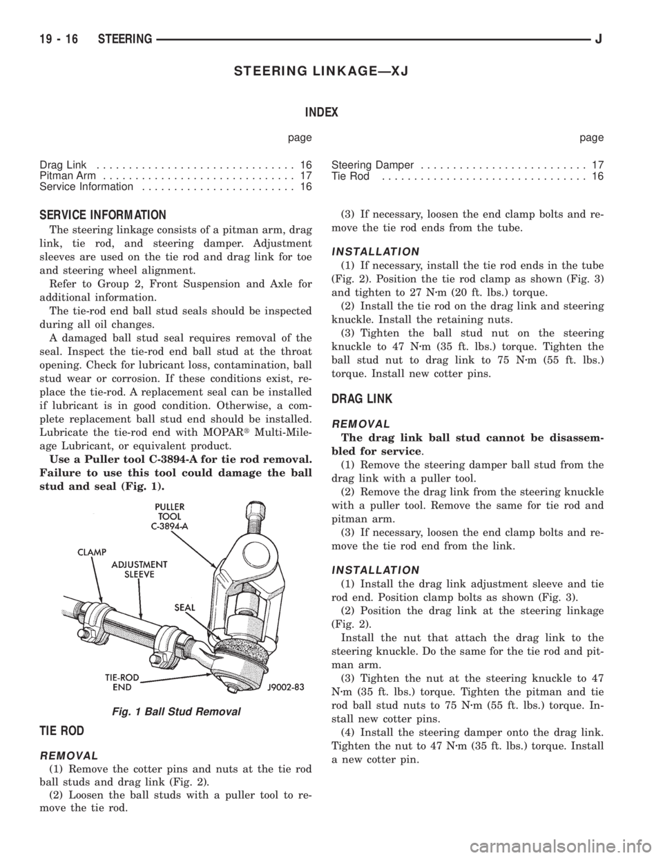
Use a Puller tool C-3894-A for tie rod removal.
Failure to use this tool could damage the ball
stud and seal (Fig. 1).
TIE ROD
REMOVAL
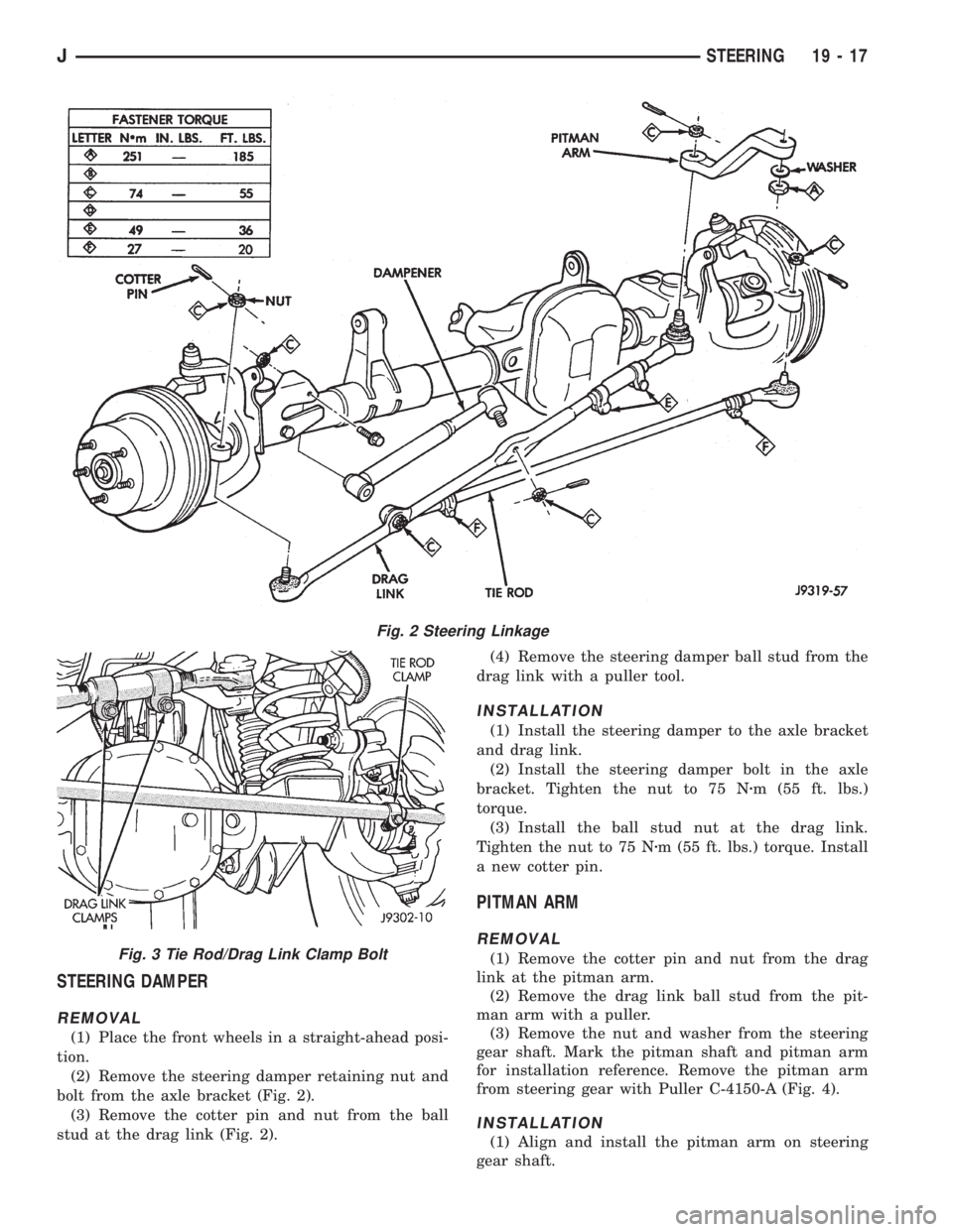
(1) Remove the cotter pins and nuts at the tie rod
ball studs and drag link (Fig. 2).
(2) Loosen the ball studs with a puller tool to re-
move the tie rod.(3) If necessary, loosen the end clamp bolts and re-
move the tie rod ends from the tube.
INSTALLATION
(1) If necessary, install the tie rod ends in the tube
(Fig. 2). Position the tie rod clamp as shown (Fig. 3)
and tighten to 27 Nzm (20 ft. lbs.) torque.
(2) Install the tie rod on the drag link and steering
knuckle. Install the retaining nuts.
(3) Tighten the ball stud nut on the steering
knuckle to 47 Nzm (35 ft. lbs.) torque. Tighten the
ball stud nut to drag link to 75 Nzm (55 ft. lbs.)
torque. Install new cotter pins.
DRAG LINK
REMOVAL
The drag link ball stud cannot be disassem-
bled for service.
(1) Remove the steering damper ball stud from the
drag link with a puller tool.
(2) Remove the drag link from the steering knuckle
with a puller tool. Remove the same for tie rod and
pitman arm.
(3) If necessary, loosen the end clamp bolts and re-
move the tie rod end from the link.
INSTALLATION
(1) Install the drag link adjustment sleeve and tie
rod end. Position clamp bolts as shown (Fig. 3).
(2) Position the drag link at the steering linkage
(Fig. 2).
Install the nut that attach the drag link to the
steering knuckle. Do the same for the tie rod and pit-
man arm.
(3) Tighten the nut at the steering knuckle to 47
Nzm (35 ft. lbs.) torque. Tighten the pitman and tie
rod ball stud nuts to 75 Nzm (55 ft. lbs.) torque. In-
stall new cotter pins.
(4) Install the steering damper onto the drag link.
Tighten the nut to 47 Nzm (35 ft. lbs.) torque. Install
a new cotter pin.
Fig. 1 Ball Stud Removal
19 - 16 STEERINGJ
Page 1501 of 2158
STEERING DAMPER
REMOVAL
(1) Place the front wheels in a straight-ahead posi-
tion.
(2) Remove the steering damper retaining nut and
bolt from the axle bracket (Fig. 2).
(3) Remove the cotter pin and nut from the ball
stud at the drag link (Fig. 2).(4) Remove the steering damper ball stud from the
drag link with a puller tool.
INSTALLATION
(1) Install the steering damper to the axle bracket
and drag link.
(2) Install the steering damper bolt in the axle
bracket. Tighten the nut to 75 Nzm (55 ft. lbs.)
torque.
(3) Install the ball stud nut at the drag link.
Tighten the nut to 75 Nzm (55 ft. lbs.) torque. Install
a new cotter pin.
PITMAN ARM
REMOVAL
(1) Remove the cotter pin and nut from the drag
link at the pitman arm.
(2) Remove the drag link ball stud from the pit-
man arm with a puller.
(3) Remove the nut and washer from the steering
gear shaft. Mark the pitman shaft and pitman arm
for installation reference. Remove the pitman arm
from steering gear with Puller C-4150-A (Fig. 4).
INSTALLATION
(1) Align and install the pitman arm on steering
gear shaft.
Fig. 2 Steering Linkage
Fig. 3 Tie Rod/Drag Link Clamp Bolt
JSTEERING 19 - 17
Page 1504 of 2158
(3) If necessary, loosen the end clamp bolts and re-
move the tie rod end from the tube.
INSTALLATION
(1) If necessary, install the tie rod end in the tube
(Fig. 2). Position the tie rod clamp as shown (Fig. 3).
Tighten the ball-stud end clamp bolts to 49 Nzm (36 ft.
lbs.) torque.
(2) Install the tie rod on the drag link and steering
knuckles. Install the retaining nuts. Install the steer-
ing damper to the tie rod.
(3) Tighten the ball stud nut on the steering
knuckle to 47 Nzm (35 ft. lbs.) torque. Tighten the
ball stud nut to drag link to 75 Nzm (55 ft. lbs.)
torque. Tighten the steering damper nut to 74 Nzm
(55 ft. lbs.) torque. Install new cotter pins.
DRAG LINK
REMOVAL
(1) Remove the cotter pins and nuts at the tie rod
and pitman arm (Fig. 2).
(2) Remove the drag link from the tie rod and pit-
man arm with a puller tool.
(3) If necessary, loosen the end clamp bolts and re-
move the tie rod ends from the tube.
INSTALLATION
(1) Install the drag link adjustment sleeve and tie
rod ends. Position clamp bolts as shown (Fig. 3).
(2) Position the drag link at the steering linkage
(Fig. 2).
Install the drag link to tie rod and pitman arm.
(3) Tighten the nut at the pitman arm to 74 Nzm
(55 ft. lbs.) torque. Tighten the tie rod ball stud nut
to 75 Nzm (55 ft. lbs.) torque. Install new cotter pins.
STEERING DAMPER
REMOVAL
(1) Place the front wheels in a straight-ahead position.
(2) Remove the steering damper retaining nut and
bolt from the axle bracket (Fig. 2).
(3) Remove the cotter pin and nut from the ball
stud at the tie rod (Fig. 2).
(4) Remove the steering damper ball stud from the
tie rod with a puller tool.
INSTALLATION
(1) Install the steering damper to the axle bracket
and tie rod.
(2) Install the steering damper bolt in the axle
bracket. Tighten the nut to 74 Nzm (55 ft. lbs.) torque.
(3) Install the ball stud nut at the tie rod. Tighten
the nut to 74 Nzm (55 ft. lbs.) torque. Install a new
cotter pin.
PITMAN ARM
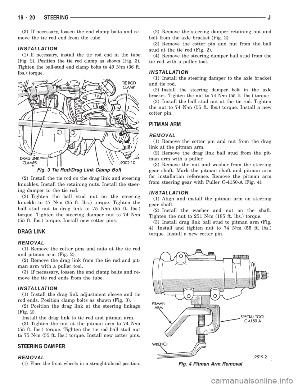
REMOVAL
(1) Remove the cotter pin and nut from the drag
link at the pitman arm.
(2) Remove the drag link ball stud from the pit-
man arm with a puller.
(3) Remove the nut and washer from the steering
gear shaft. Mark the pitman shaft and pitman arm
for installation reference. Remove the pitman arm
from steering gear with Puller C-4150-A (Fig. 4).
INSTALLATION
(1) Align and install the pitman arm on steering
gear shaft.
(2) Install the washer and nut on the shaft.
Tighten the nut to 251 Nzm (185 ft. lbs.) torque.
(3) Install drag link ball stud to pitman arm (Fig.
4). Install and tighten nut to 74 Nzm (55 ft. lbs.)
torque. Install a new cotter pin.
Fig. 4 Pitman Arm Removal
Fig. 3 Tie Rod/Drag Link Clamp Bolt
19 - 20 STEERINGJ