1995 JEEP XJ wheel torque
[x] Cancel search: wheel torquePage 1340 of 2158
(29) Disconnect the exhaust pipe from the mani-
fold.
(30) Disconnect the engine speed sensor wire con-
nection.
(31) Remove the exhaust pipe support.
(32) Remove the flywheel and converter housing
access cover.
(33)Vehicles with Automatic Transmission:
(a) Mark the converter and drive plate location.
(b) Remove the converter-to-drive plate bolts.
(34) Remove the upper flywheel and converter
housing bolts and loosen the bottom bolts.
(35) Remove the engine mount cushion-to-engine
compartment bracket bolts.
(36) Lower the vehicle.
(37) Attach a lifting device to the engine.
(38) Raise the engine off the front supports.
(39) Place a support or floor jack under the con-
verter (or flywheel) housing.
(40) Remove the remaining converter (or flywheel)
housing bolts.
(41) Lift the engine out of the engine compart-
ment.
INSTALLATION
CAUTION: When installing the engine into a vehicle
equipped with an automatic transmission, be care-
ful not to damage the trigger wheel on the flywheel.
(1) Attach a lifting device to the engine and lower
the engine into the engine compartment. For easier
installation, it may be necessary to remove the en-
gine mount cushions from the engine mount bracket
as an aide in alignment of the engine to the trans-
mission.
(2)Vehicles with Manual Transmission:
(a) Insert the transmission shaft into the clutch
spline.
(b) Align the flywheel housing with the engine.(c) Install and tighten the flywheel housing lower
bolts finger tight.
(3)Vehicles with Automatic Transmission:
(a) Align the transmission torque converter hous-
ing with the engine.
(b) Loosely install the converter housing lower
bolts and install the next higher bolt and nut on
each side.
(c) Tighten all 4 bolts finger tight.
(4) Install the engine mount cushions (if removed).
(5) Lower the engine and engine mount cushions
onto the engine compartment brackets. Install the
bolts and finger tighten the nuts.
(6) Remove the engine lifting device.
(7) Raise and support the vehicle.
(8) Install the remaining flywheel and converter
housing bolts. Tighten all bolts to 38 Nzm (28 ft. lbs.)
torque.
(9)Vehicles with Automatic Transmission:
(a) Install the converter-to-drive plate bolts.
(b) Ensure the installation reference marks are
aligned.
(10) Install the flywheel and converter housing ac-
cess cover.
(11) Install the exhaust pipe support and tighten
the screw.
(12) Tighten the engine mount-to-bracket bolts.
(13) Connect the engine speed sensor wire connec-
tions and tighten the screws.
(14) Connect the exhaust pipe to the manifold.
(15) Install the starter motor and connect the ca-
ble.
(16) Connect the wires to the starter motor sole-
noid.
(17) Lower the vehicle.
(18) Connect all the vacuum hoses and wire con-
nectors identified during engine removal.
(19) If equipped with power steering:
(a) Remove the protective caps
(b) Connect the hoses to the fittings at the steer-
ing gear. Tighten the nut to 52 Nzm (38 ft. lbs.)
torque.
(c) Fill the pump reservoir with fluid.
(20) Install the power brake vacuum check valve to
the booster, if equipped.
(21) Connect the fuel inlet and return hoses at the
fuel rail. Verify that the quick-connect fitting assem-
bly fits securely over the fuel lines by giving the fuel
lines a firm tug.
(22) Install the fuel line bracket to the intake man-
ifold.
(23) Connect the distributor electrical connector
and oil pressure switch connector.
(24) Connect the injection system wire harness
connector on the dash panel.
(25) Connect the line pressure cable (if equipped
with automatic transmission).
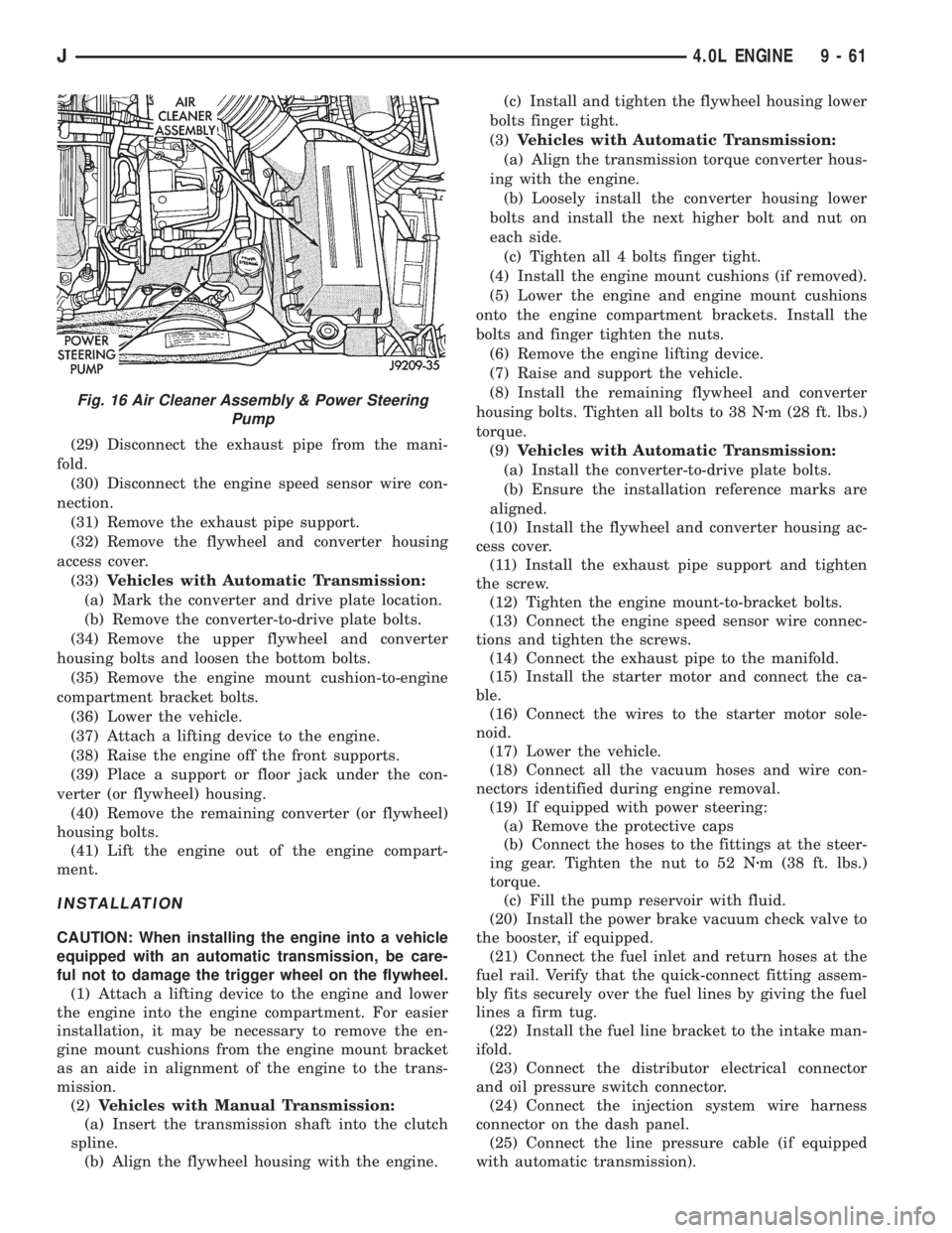
Fig. 16 Air Cleaner Assembly & Power Steering
Pump
J4.0L ENGINE 9 - 61
Page 1342 of 2158
(18) Disconnect the oxygen sensor wire connector.
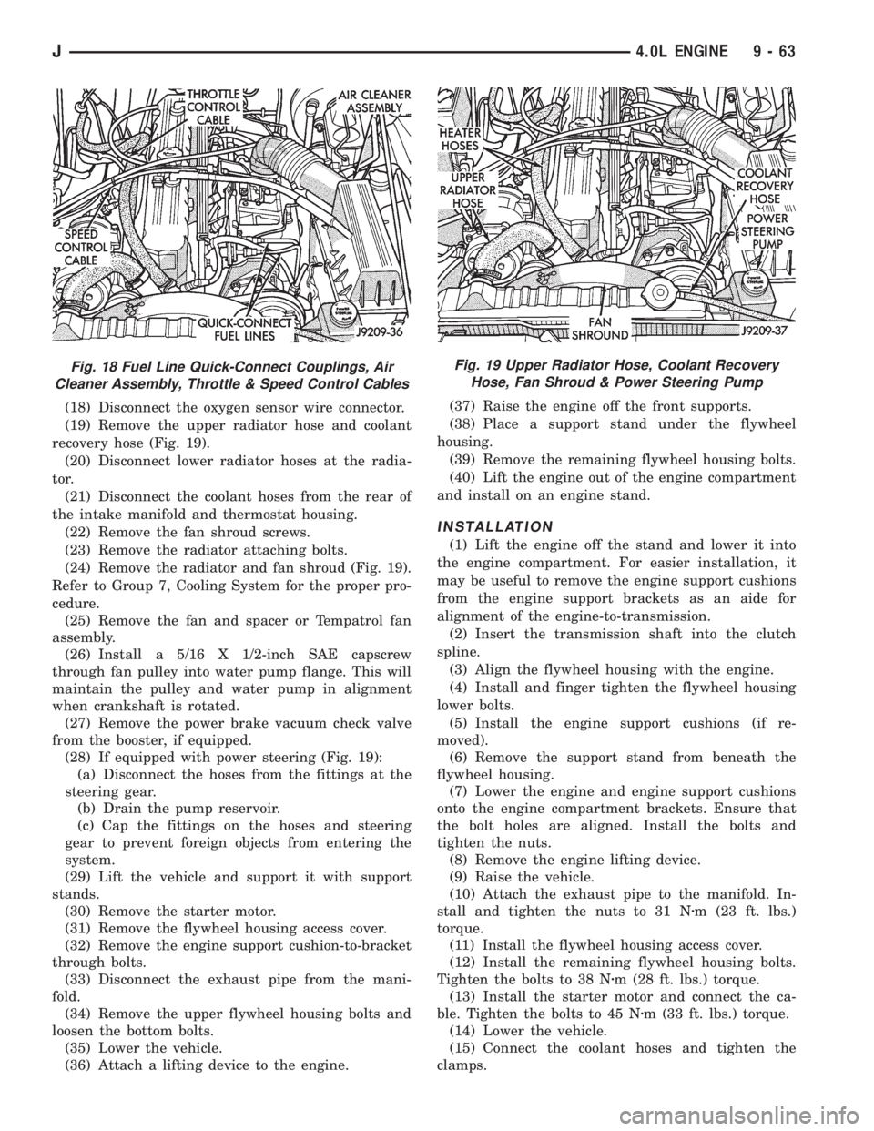
(19) Remove the upper radiator hose and coolant
recovery hose (Fig. 19).
(20) Disconnect lower radiator hoses at the radia-
tor.
(21) Disconnect the coolant hoses from the rear of
the intake manifold and thermostat housing.
(22) Remove the fan shroud screws.
(23) Remove the radiator attaching bolts.
(24) Remove the radiator and fan shroud (Fig. 19).
Refer to Group 7, Cooling System for the proper pro-
cedure.
(25) Remove the fan and spacer or Tempatrol fan
assembly.
(26) Install a 5/16 X 1/2-inch SAE capscrew
through fan pulley into water pump flange. This will
maintain the pulley and water pump in alignment
when crankshaft is rotated.
(27) Remove the power brake vacuum check valve
from the booster, if equipped.
(28) If equipped with power steering (Fig. 19):
(a) Disconnect the hoses from the fittings at the
steering gear.
(b) Drain the pump reservoir.
(c) Cap the fittings on the hoses and steering
gear to prevent foreign objects from entering the
system.
(29) Lift the vehicle and support it with support
stands.
(30) Remove the starter motor.
(31) Remove the flywheel housing access cover.
(32) Remove the engine support cushion-to-bracket
through bolts.
(33) Disconnect the exhaust pipe from the mani-
fold.
(34) Remove the upper flywheel housing bolts and
loosen the bottom bolts.
(35) Lower the vehicle.
(36) Attach a lifting device to the engine.(37) Raise the engine off the front supports.
(38) Place a support stand under the flywheel
housing.
(39) Remove the remaining flywheel housing bolts.
(40) Lift the engine out of the engine compartment
and install on an engine stand.
INSTALLATION
(1) Lift the engine off the stand and lower it into
the engine compartment. For easier installation, it
may be useful to remove the engine support cushions
from the engine support brackets as an aide for
alignment of the engine-to-transmission.
(2) Insert the transmission shaft into the clutch
spline.
(3) Align the flywheel housing with the engine.
(4) Install and finger tighten the flywheel housing
lower bolts.
(5) Install the engine support cushions (if re-
moved).
(6) Remove the support stand from beneath the
flywheel housing.
(7) Lower the engine and engine support cushions
onto the engine compartment brackets. Ensure that
the bolt holes are aligned. Install the bolts and
tighten the nuts.
(8) Remove the engine lifting device.
(9) Raise the vehicle.
(10) Attach the exhaust pipe to the manifold. In-
stall and tighten the nuts to 31 Nzm (23 ft. lbs.)
torque.
(11) Install the flywheel housing access cover.
(12) Install the remaining flywheel housing bolts.
Tighten the bolts to 38 Nzm (28 ft. lbs.) torque.
(13) Install the starter motor and connect the ca-
ble. Tighten the bolts to 45 Nzm (33 ft. lbs.) torque.
(14) Lower the vehicle.
(15) Connect the coolant hoses and tighten the
clamps.
Fig. 18 Fuel Line Quick-Connect Couplings, Air
Cleaner Assembly, Throttle & Speed Control CablesFig. 19 Upper Radiator Hose, Coolant Recovery
Hose, Fan Shroud & Power Steering Pump
J4.0L ENGINE 9 - 63
Page 1356 of 2158
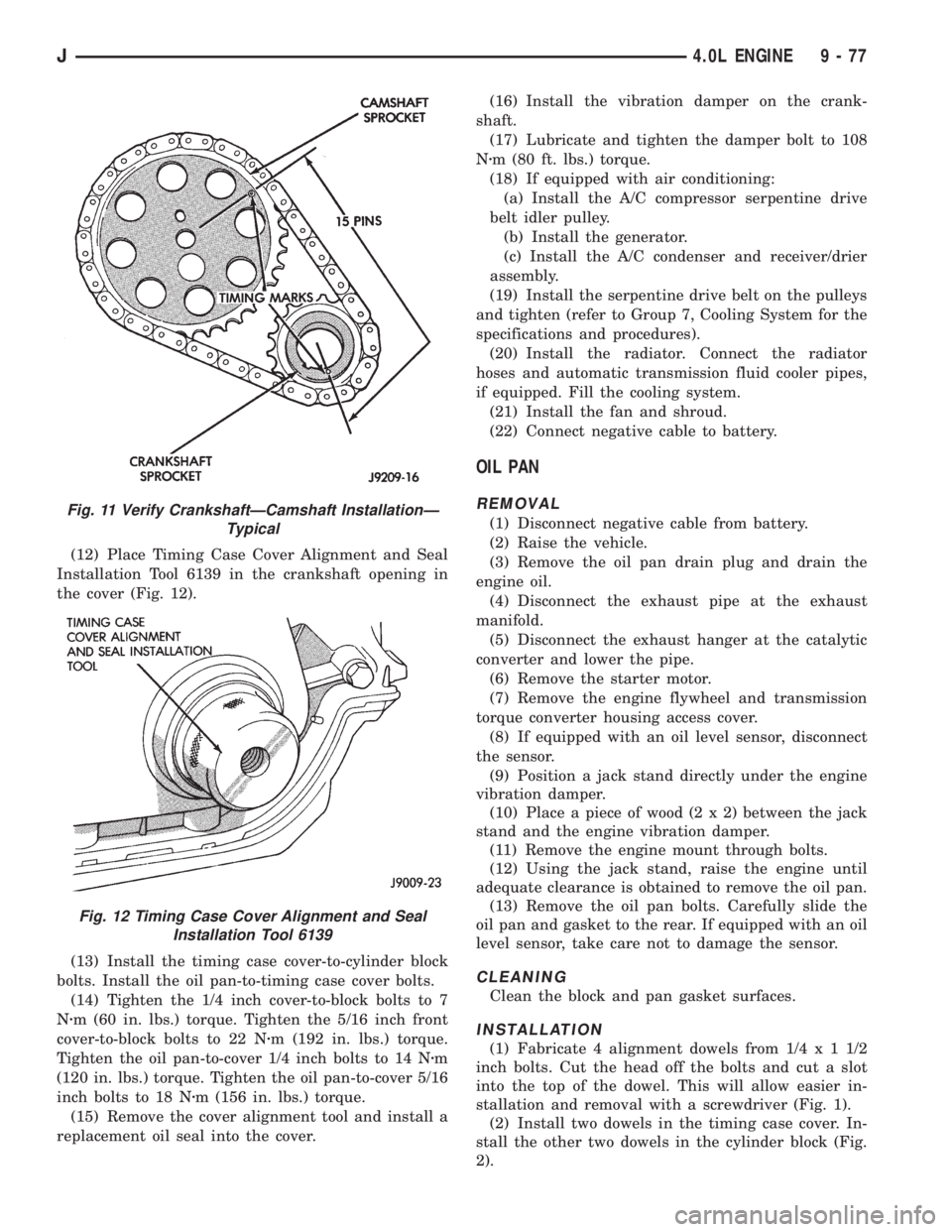
(12) Place Timing Case Cover Alignment and Seal
Installation Tool 6139 in the crankshaft opening in
the cover (Fig. 12).
(13) Install the timing case cover-to-cylinder block
bolts. Install the oil pan-to-timing case cover bolts.
(14) Tighten the 1/4 inch cover-to-block bolts to 7
Nzm (60 in. lbs.) torque. Tighten the 5/16 inch front
cover-to-block bolts to 22 Nzm (192 in. lbs.) torque.
Tighten the oil pan-to-cover 1/4 inch bolts to 14 Nzm
(120 in. lbs.) torque. Tighten the oil pan-to-cover 5/16
inch bolts to 18 Nzm (156 in. lbs.) torque.
(15) Remove the cover alignment tool and install a
replacement oil seal into the cover.(16) Install the vibration damper on the crank-
shaft.
(17) Lubricate and tighten the damper bolt to 108
Nzm (80 ft. lbs.) torque.
(18) If equipped with air conditioning:
(a) Install the A/C compressor serpentine drive
belt idler pulley.
(b) Install the generator.
(c) Install the A/C condenser and receiver/drier
assembly.
(19) Install the serpentine drive belt on the pulleys
and tighten (refer to Group 7, Cooling System for the
specifications and procedures).
(20) Install the radiator. Connect the radiator
hoses and automatic transmission fluid cooler pipes,
if equipped. Fill the cooling system.
(21) Install the fan and shroud.
(22) Connect negative cable to battery.
OIL PAN
REMOVAL
(1) Disconnect negative cable from battery.
(2) Raise the vehicle.
(3) Remove the oil pan drain plug and drain the
engine oil.
(4) Disconnect the exhaust pipe at the exhaust
manifold.
(5) Disconnect the exhaust hanger at the catalytic
converter and lower the pipe.
(6) Remove the starter motor.
(7) Remove the engine flywheel and transmission
torque converter housing access cover.
(8) If equipped with an oil level sensor, disconnect
the sensor.
(9) Position a jack stand directly under the engine
vibration damper.
(10) Place a piece of wood (2 x 2) between the jack
stand and the engine vibration damper.
(11) Remove the engine mount through bolts.
(12) Using the jack stand, raise the engine until
adequate clearance is obtained to remove the oil pan.
(13) Remove the oil pan bolts. Carefully slide the
oil pan and gasket to the rear. If equipped with an oil
level sensor, take care not to damage the sensor.
CLEANING
Clean the block and pan gasket surfaces.
INSTALLATION
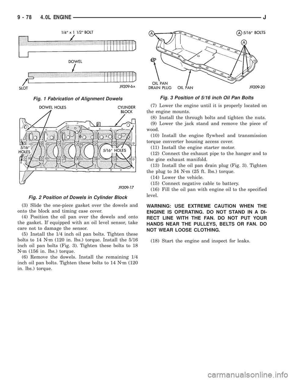
(1) Fabricate 4 alignment dowels from 1/4 x 1 1/2
inch bolts. Cut the head off the bolts and cut a slot
into the top of the dowel. This will allow easier in-
stallation and removal with a screwdriver (Fig. 1).
(2) Install two dowels in the timing case cover. In-
stall the other two dowels in the cylinder block (Fig.
2).
Fig. 11 Verify CrankshaftÐCamshaft InstallationÐ
Typical
Fig. 12 Timing Case Cover Alignment and Seal
Installation Tool 6139
J4.0L ENGINE 9 - 77
Page 1357 of 2158
(3) Slide the one-piece gasket over the dowels and
onto the block and timing case cover.
(4) Position the oil pan over the dowels and onto
the gasket. If equipped with an oil level sensor, take
care not to damage the sensor.
(5) Install the 1/4 inch oil pan bolts. Tighten these
bolts to 14 Nzm (120 in. lbs.) torque. Install the 5/16
inch oil pan bolts (Fig. 3). Tighten these bolts to 18
Nzm (156 in. lbs.) torque.
(6) Remove the dowels. Install the remaining 1/4
inch oil pan bolts. Tighten these bolts to 14 Nzm (120
in. lbs.) torque.(7) Lower the engine until it is properly located on
the engine mounts.
(8) Install the through bolts and tighten the nuts.
(9) Lower the jack stand and remove the piece of
wood.
(10) Install the engine flywheel and transmission
torque converter housing access cover.
(11) Install the engine starter motor.
(12) Connect the exhaust pipe to the hanger and to
the gine exhaust manifold.
(13) Install the oil pan drain plug (Fig. 3). Tighten
the plug to 34 Nzm (25 ft. lbs.) torque.
(14) Lower the vehicle.
(15) Connect negative cable to battery.
(16) Fill the oil pan with engine oil to the specified
level.
WARNING: USE EXTREME CAUTION WHEN THE
ENGINE IS OPERATING. DO NOT STAND IN A DI-
RECT LINE WITH THE FAN. DO NOT PUT YOUR
HANDS NEAR THE PULLEYS, BELTS OR FAN. DO
NOT WEAR LOOSE CLOTHING.
(18) Start the engine and inspect for leaks.
Fig. 1 Fabrication of Alignment Dowels
Fig. 2 Position of Dowels in Cylinder Block
Fig. 3 Position of 5/16 inch Oil Pan Bolts
9 - 78 4.0L ENGINEJ
Page 1370 of 2158
REMOVAL
(1) Remove the engine flywheel or converter drive
plate.
(2) Remove the oil pan.
(3) Remove the rear main bearing cap (No.7).
(4) Push the upper seal out of the groove. Ensure
that the crankshaft and seal groove are not damaged.
(5) Remove the lower half of the seal from the
bearing cap.
INSTALLATION
(1) Wipe the seal surface area of the crankshaft
until it is clean.
(2) Apply a thin coat of engine oil.
(3) Coat the lip of the seal with engine oil.
(4) Carefully position the upper seal into the
groove in the cylinder block. The lip of the seal faces
toward the front of the engine.
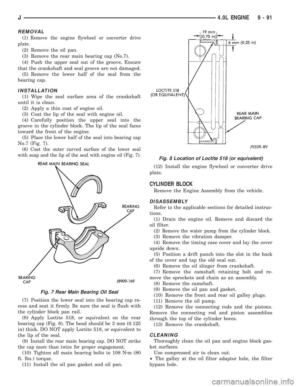
(5) Place the lower half of the seal into bearing cap
No.7 (Fig. 7).
(6) Coat the outer curved surface of the lower seal
with soap and the lip of the seal with engine oil (Fig. 7).
(7) Position the lower seal into the bearing cap re-
cess and seat it firmly. Be sure the seal is flush with
the cylinder block pan rail.
(8) Apply Loctite 518, or equivalent on the rear
bearing cap (Fig. 8). The bead should be 3 mm (0.125
in) thick. DO NOT apply Loctite 518, or equivalent to
the lip of the seal.
(9) Install the rear main bearing cap. DO NOT strike
the cap more than twice for proper engagement.
(10) Tighten all main bearing bolts to 108 Nzm (80
ft. lbs.) torque.
(11) Install the oil pan gasket and oil pan.(12) Install the engine flywheel or converter drive
plate.
CYLINDER BLOCK
Remove the Engine Assembly from the vehicle.
DISASSEMBLY
Refer to the applicable sections for detailed instruc-
tions.
(1) Drain the engine oil. Remove and discard the
oil filter.
(2) Remove the water pump from the cylinder block.
(3) Remove the vibration damper.
(4) Remove the timing case cover and lay the cover
upside down.
(5) Position a drift punch into the slot in the back
of the cover and tap the old seal out.
(6) Remove the oil slinger from crankshaft.
(7) Remove the camshaft retaining bolt and re-
move the sprockets and chain as an assembly.
(8) Remove the camshaft.
(9) Remove the oil pan and gasket.
(10) Remove the front and rear oil galley plugs.
(11) Remove the oil pump.
(12) Remove the connecting rods and the pistons.
Remove the connecting rod and piston assemblies
through the top of the cylinder bores.
(13) Remove the crankshaft.
CLEANING
Thoroughly clean the oil pan and engine block gas-
ket surfaces.
Use compressed air to clean out:
²The galley at the oil filter adaptor hole, the filter
bypass hole.
Fig. 7 Rear Main Bearing Oil Seal
Fig. 8 Location of Loctite 518 (or equivalent)
J4.0L ENGINE 9 - 91
Page 1389 of 2158
FUEL FILLER HOSE SPLASH SHIELDÐXJ
VEHICLES
REMOVAL
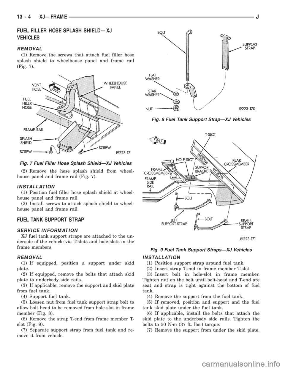
(1) Remove the screws that attach fuel filler hose
splash shield to wheelhouse panel and frame rail
(Fig. 7).
(2) Remove the hose splash shield from wheel-
house panel and frame rail (Fig. 7).
INSTALLATION
(1) Position fuel filler hose splash shield at wheel-
house panel and frame rail.
(2) Install screws to attach splash shield to wheel-
house panel and frame rail.
FUEL TANK SUPPORT STRAP
SERVICE INFORMATION
XJ fuel tank support straps are attached to the un-
derside of the vehicle via T-slots and hole-slots in the
frame members.
REMOVAL
(1) If equipped, position a support under skid
plate.
(2) If equipped, remove the bolts that attach skid
plate to underbody side rails.
(3) If applicable, remove the support and skid plate
from fuel tank.
(4) Support fuel tank.
(5) Loosen nut from fuel tank support strap bolt to
allow bolt head to be removed from hole-slot in frame
member (Fig. 8).
(6) Remove the strap T-end from frame member T-
slot (Fig. 9).
(7) Separate support strap from fuel tank and re-
move it from vehicle.
INSTALLATION
(1) Position support strap around fuel tank.
(2) Insert strap T-end in frame member T-slot.
(3) Insert bolt in hole-slot in frame member.
Tighten nut on the bolt until bolt-head and T-end are
seat and strap is tight against the bottom of fuel
tank.
(4) Remove the support from the fuel tank.
(5) If removed, position and support and the fuel
tank skid plate under the fuel tank.
(6) If applicable, install the bolts that attach the
skid plate to the underbody side rails. Tighten the
bolts to 50 Nzm (37 ft. lbs.) torque.
(7) Remove the support from under the skid plate.
Fig. 7 Fuel Filler Hose Splash ShieldÐXJ Vehicles
Fig. 8 Fuel Tank Support StrapÐXJ Vehicles
Fig. 9 Fuel Tank Support StrapsÐXJ Vehicles
13 - 4 XJÐFRAMEJ
Page 1398 of 2158
The frame is constructed of high-strength channel
steel siderails and crossmembers. The crossmembers
join the siderails and retain them in alignment in re-
lation to each other. This provides resistance to
frame twists and strains.
FRAME STRAIGHTENING
When necessary, a conventional frame that is bent
or twisted can be straightened by application of heat.
The temperature must not exceed 566ÉC (1050ÉF).
The use of a specially designed heat crayon can de-
termine the desired temperature. Excessive heat will
decrease the strength of the metal and result in a
weakened frame.
Welding the joints around riveted cross members
and frame side rails is not recommended.
A straightening repair process should be limited to
frame members that are not severely damaged.
FRAME REPAIRS
DRILLING HOLES
Do not drill holes in frame side rail top and bottom
flanges, metal fatigue can result causing frame fail-
ure. Holes drilled in the side of the frame rail must
be at least 38 mm (1.5 in.) from the top and bottom
flanges.
Additional drill holes should be located away from
existing holes.
WELDING
Use MIG, TIG or arc welding equipment to repair
welded frame components.
Frame components that have been damaged should
be inspected for cracks before returning the vehicle
to use. If cracks are found in accessible frame com-
ponents perform the following procedures.
(1) Drill a hole at each end of the crack with a 3
mm (O.125 in.) diameter drill bit.
(2) Using a suitable die grinder with 3 inch cut off
wheel, V-groove the crack to allow 100% weld pene-
tration.
(3) Weld the crack.
(4) If necessary when a side rail is repaired, grind
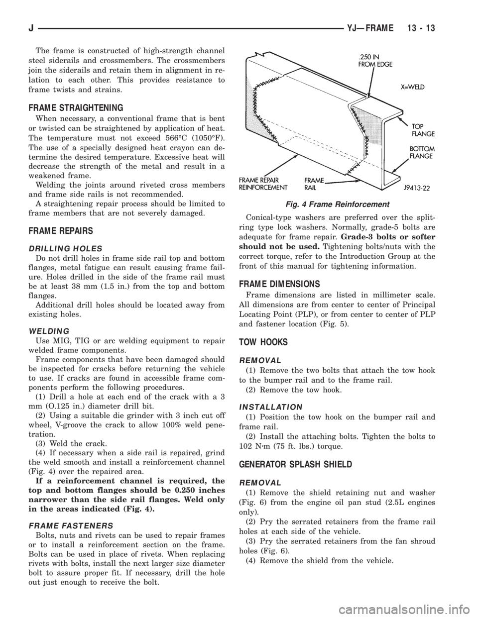
the weld smooth and install a reinforcement channel
(Fig. 4) over the repaired area.
If a reinforcement channel is required, the
top and bottom flanges should be 0.250 inches
narrower than the side rail flanges. Weld only
in the areas indicated (Fig. 4).
FRAME FASTENERS
Bolts, nuts and rivets can be used to repair frames
or to install a reinforcement section on the frame.
Bolts can be used in place of rivets. When replacing
rivets with bolts, install the next larger size diameter
bolt to assure proper fit. If necessary, drill the hole
out just enough to receive the bolt.Conical-type washers are preferred over the split-
ring type lock washers. Normally, grade-5 bolts are
adequate for frame repair.Grade-3 bolts or softer
should not be used.Tightening bolts/nuts with the
correct torque, refer to the Introduction Group at the
front of this manual for tightening information.
FRAME DIMENSIONS
Frame dimensions are listed in millimeter scale.
All dimensions are from center to center of Principal
Locating Point (PLP), or from center to center of PLP
and fastener location (Fig. 5).
TOW HOOKS
REMOVAL
(1) Remove the two bolts that attach the tow hook
to the bumper rail and to the frame rail.
(2) Remove the tow hook.
INSTALLATION
(1) Position the tow hook on the bumper rail and
frame rail.
(2) Install the attaching bolts. Tighten the bolts to
102 Nzm (75 ft. lbs.) torque.
GENERATOR SPLASH SHIELD
REMOVAL
(1) Remove the shield retaining nut and washer
(Fig. 6) from the engine oil pan stud (2.5L engines
only).
(2) Pry the serrated retainers from the frame rail
holes at each side of the vehicle.
(3) Pry the serrated retainers from the fan shroud
holes (Fig. 6).
(4) Remove the shield from the vehicle.
Fig. 4 Frame Reinforcement
JYJÐFRAME 13 - 13
Page 1417 of 2158
(1) Disconnect negative battery cable.
(2) Remove the fuel filler cap. Using an approved
portable gasoline siphon/storage tank, drain fuel
tank.
(3) Raise and support vehicle.
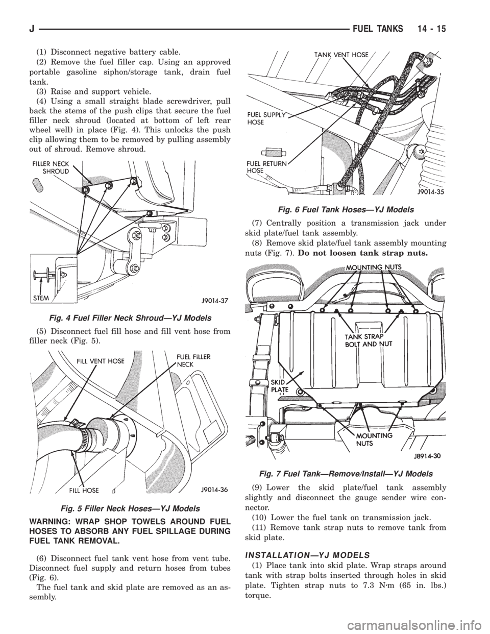
(4) Using a small straight blade screwdriver, pull
back the stems of the push clips that secure the fuel
filler neck shroud (located at bottom of left rear
wheel well) in place (Fig. 4). This unlocks the push
clip allowing them to be removed by pulling assembly
out of shroud. Remove shroud.
(5) Disconnect fuel fill hose and fill vent hose from
filler neck (Fig. 5).
WARNING: WRAP SHOP TOWELS AROUND FUEL
HOSES TO ABSORB ANY FUEL SPILLAGE DURING
FUEL TANK REMOVAL.
(6) Disconnect fuel tank vent hose from vent tube.
Disconnect fuel supply and return hoses from tubes
(Fig. 6).
The fuel tank and skid plate are removed as an as-
sembly.(7) Centrally position a transmission jack under
skid plate/fuel tank assembly.
(8) Remove skid plate/fuel tank assembly mounting
nuts (Fig. 7).Do not loosen tank strap nuts.
(9) Lower the skid plate/fuel tank assembly
slightly and disconnect the gauge sender wire con-
nector.
(10) Lower the fuel tank on transmission jack.
(11) Remove tank strap nuts to remove tank from
skid plate.
INSTALLATIONÐYJ MODELS
(1) Place tank into skid plate. Wrap straps around
tank with strap bolts inserted through holes in skid
plate. Tighten strap nuts to 7.3 Nzm (65 in. lbs.)
torque.
Fig. 4 Fuel Filler Neck ShroudÐYJ Models
Fig. 5 Filler Neck HosesÐYJ Models
Fig. 6 Fuel Tank HosesÐYJ Models
Fig. 7 Fuel TankÐRemove/InstallÐYJ Models
JFUEL TANKS 14 - 15