1995 JEEP XJ wheel torque
[x] Cancel search: wheel torquePage 1507 of 2158
PITMAN SHAFT SEALSÐIN CAR REPLACEMENT
REMOVAL
(1) Remove pitman arm from gear. Refer to Pitman
Arm Removal in Steering Linkage.
(2) Clean exposed end of pitman shaft and hous-
ing. Use a wire brush to clean the shaft splines.
(3) Remove retaining ring with snap ring pliers
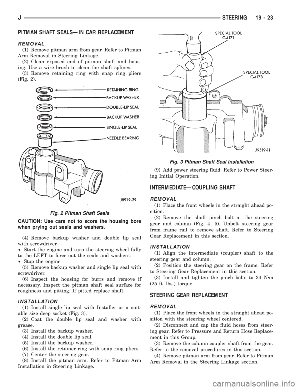
(Fig. 2).
CAUTION: Use care not to score the housing bore
when prying out seals and washers.
(4) Remove backup washer and double lip seal
with screwdriver.
²Start the engine and turn the steering wheel fully
to the LEFT to force out the seals and washers.
²Stop the engine
(5) Remove backup washer and single lip seal with
screwdriver.
(6) Inspect the housing for burrs and remove if
necessary. Inspect the pitman shaft seal surface for
roughness and pitting. If pitted replace shaft.
INSTALLATION
(1) Install single lip seal with Installer or a suit-
able size deep socket (Fig. 3).
(2) Coat the double lip seal and washer with
grease.
(3) Install the backup washer.
(4) Install the double lip seal.
(5) Install the backup washer.
(6) Install the retainer ring with snap ring pliers.
(7) Center the steering gear.
(8) Install the pitman arm. Refer to Pitman Arm
Installation in Steering Linkage.(9) Add power steering fluid. Refer to Power Steer-
ing Initial Operation.
INTERMEDIATEÐCOUPLING SHAFT
REMOVAL
(1) Place the front wheels in the straight ahead po-
sition.
(2) Remove the shaft pinch bolt at the steering
gear and column (Fig. 4, 5). Unbolt steering gear
from frame rail to remove shaft. Refer to Steering
Gear Replacement in this section.
INSTALLATION
(1) Align the intermediate (coupler) shaft to the
steering gear and column.
(2) Position the steering gear on the frame. Refer
to Steering Gear Replacement in this section.
(3) Install and tighten the pinch bolts to 34 Nzm
(25 ft. lbs.) torque.
STEERING GEAR REPLACEMENT
REMOVAL
(1) Place the front wheels in the straight ahead po-
sition with the steering wheel centered.
(2) Disconnect and cap the fluid hoses from steer-
ing gear. Refer to Pressure and Return Hose Replace-
ment in this Group.
(3) Remove the column coupler shaft from the gear.
Refer to the removal procedures in this section.
(4) Remove pitman arm from gear. Refer to Pitman
Arm Removal in the Steering Linkage section.
Fig. 2 Pitman Shaft Seals
Fig. 3 Pitman Shaft Seal Installation
JSTEERING 19 - 23
Page 1523 of 2158
(2) Wrap a single layer of plastic tape around the
pitman shaft threads and splines. This will protect
the replacement seals during installation.
(3) Install the seal with a suitable size socket.
(4) Remove the tape from the shaft.
(5) Center the steering gear.
(6) Align and install the pitman arm.
(7) Install the washer and retaining nut on the pit-
man shaft. Tighten the nut to 251 Nzm (185 ft. lbs.)
torque.
GEAR ADJUSTMENTS IN VEHICLE
REMOVE
(1) Raise and support the vehicle.
(2) Mark the pitman shaft and pitman arm for in-
stallation reference. Remove the pitman arm from
the shaft.
(3) Loosen the adjuster lock nut then back the ad-
juster plug off 1/4 turn.
(4) Remove the steering wheel horn pad.
(5) Turn the steering wheel in one direction until
stopped by the gear. Then turn back 1/2 turn.
CAUTION: Do not turn the steering wheel hard
against the internal stops when the linkage is re-
moved. This could result in damage to the recircu-
lating ball guides.
MEASURE
Place a low calibration (50 in. lbs.) torque wrench
and socket on the steering wheel nut. Rotate the
wrench and nut through a 90 degree arc (1/4 turn).
This will measure the worm shaft bearing preload.
ADJUST WORMSHAFT BEARING PRELOAD
TORQUE
(1) Adjust the preload by tightening the adjuster
plug. The preload should be 0.6 to 1 Nzm(5to8in.
lbs.) torque.
Steering column/shaft misalignment or damage will
increase the amount of torque required to rotate the
steering wheel. If the rotating torque is exceptionally
high, inspect the steering column/shaft alignment. If
the alignment is correct, remove the steering gear,
determine the cause of the high preload torque, and
repair as necessary.
(2) Tighten the adjuster locknut to 68 Nzm (50 ft.
lbs.) torque. Measure the preload torque. If neces-
sary, adjust the preload torque again.
ADJUST OVERCENTER DRAG TORQUE
(1) Turn the steering wheel from one stop to the
other and count the total numbers of turns. Turn the
wheel back in reverse direction 1/2 the total number
of turns to center the steering gear.(2) Turn the over center adjusting screw in to re-
move all lash between the ball nut and pitman shaft
sector teeth. Hold the adjustment screw and tighten
the lock nut to 34 Nzm (25 ft. lbs.) torque.
(3) Check the torque at the steering wheel by tak-
ing the highest reading as the wheel is turned
through the center position.
(4) The overcenter drag torque should be 0.5 to 1
Nzm (4 to 10 in. lbs.).
(5) If necessary, loosen the lock nut and adjust the
over center adjuster screw to obtain the proper
torque. Re-tighten the lock nut to the lock nut.
(6) After tightening the locknut, measure the over-
center drag torque again and readjust the torque, if
necessary.
INSTALL
(1) Align the installation reference marks and in-
stall the pitman arm.
(2) Install and tighten the pitman shaft nut and
washer to 251 Nzm (185 ft. lbs.) torque.
(3) Install the horn button.
GEAR DISASSEMBLY
(1) Rotate the wormshaft from stop-to-stop and
count the number of rotations. Rotate the wormshaft
in the reverse direction 1/2 of the total number of ro-
tations to center it and the ball nut.
(2) Remove the pitman shaft adjustment screw
locknut. Remove the cover retaining bolts, cover, and
gasket (Fig. 3).
(3) Slide the adjustment screw head (Fig. 3) out of
the pitman shaft T-slot and remove it and the
shim(s).
(4) Retain the shim(s) for end-play measurement
during assembly.
(5) Remove the pitman shaft, the wormshaft bear-
ing preload torque adjustment cap locknut, and the
adjustment cap (Fig. 2).
(6) Remove the wormshaft and the ball nut (Fig.
2).
(7) Remove (pry) the pitman shaft and the worm-
shaft seals from the steering gear housing (Fig. 3).
WORMSHAFT AND BALL NUT DISASSEMBLY
(1) Remove the upper bearing from the wormshaft
(Fig. 2).
CAUTION: Do not allow the ball nut to rotate freely
and travel to either extreme end of the wormshaft.
This could damage the tangs at the ends of the re-
circulating ball guides (Fig. 3).
(2) Remove the recirculating ball guide clamp re-
taining screws, the clamp and the guides (Fig. 2).
Separate the half-guides and place the recirculating
balls aside in a container.
JSTEERING 19 - 39
Page 1529 of 2158
(4) Hold pitman shaft adjustment screw and
tighten adjuster lock nut to 34 Nzm (25 ft. lbs.)
torque.
INTERMEDIATE (COUPLER) SHAFT
REMOVAL
(1) Place the front wheels in the straight ahead po-
sition.
(2) Remove the shaft pinch bolt at the steering
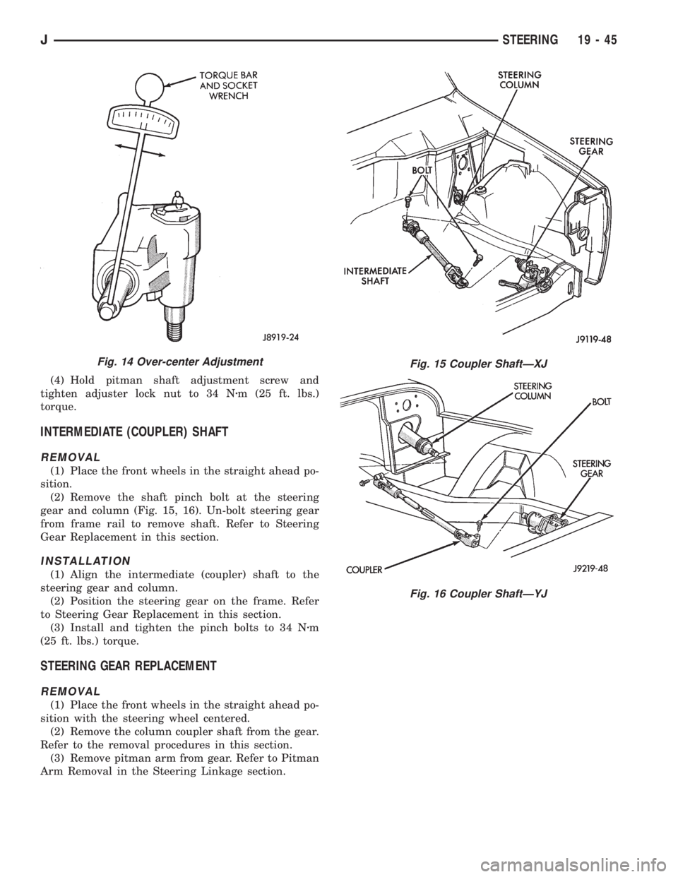
gear and column (Fig. 15, 16). Un-bolt steering gear
from frame rail to remove shaft. Refer to Steering
Gear Replacement in this section.
INSTALLATION
(1) Align the intermediate (coupler) shaft to the
steering gear and column.
(2) Position the steering gear on the frame. Refer
to Steering Gear Replacement in this section.
(3) Install and tighten the pinch bolts to 34 Nzm
(25 ft. lbs.) torque.
STEERING GEAR REPLACEMENT
REMOVAL
(1) Place the front wheels in the straight ahead po-
sition with the steering wheel centered.
(2) Remove the column coupler shaft from the gear.
Refer to the removal procedures in this section.
(3) Remove pitman arm from gear. Refer to Pitman
Arm Removal in the Steering Linkage section.
Fig. 14 Over-center AdjustmentFig. 15 Coupler ShaftÐXJ
Fig. 16 Coupler ShaftÐYJ
JSTEERING 19 - 45
Page 1533 of 2158
AIRBAG MODULE REMOVEÐINSTALL
WARNING: THIS AIRBAG SYSTEM IS A SENSITIVE,
COMPLEX MECHANICAL UNIT. BEFORE ATTEMPT-
ING TO REMOVE OR INSTALL THE AIRBAG SYS-
TEM OR RELATED STEERING WHEEL AND
STEERING COLUMN COMPONENTS YOU MUST
FIRST DISARM THE AIRBAG FIRING MECHANISM.
FAILURE TO DO SO COULD RESULT IN ACCIDEN-
TAL DEPLOYMENT AND POSSIBLE PERSONAL IN-
JURY.
When removing a deployed airbag module,
rubber gloves, eye protection and long-sleeved
shirt should be worn. There may be deposits on
the airbag module and other interior surfaces,
which can cause irritation to the skin and eyes
in large doses.
(1) Disconnect battery negative cable and isolate.
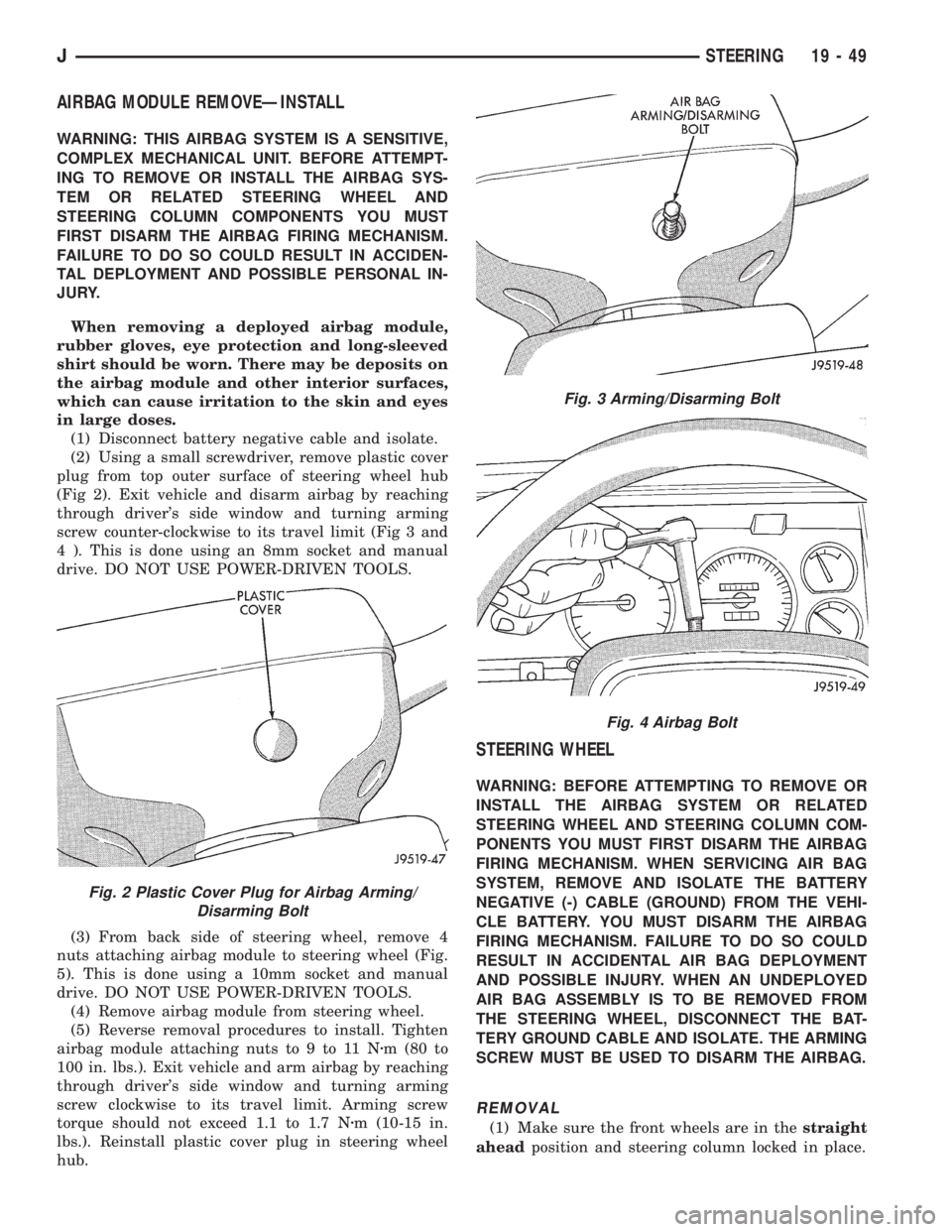
(2) Using a small screwdriver, remove plastic cover
plug from top outer surface of steering wheel hub
(Fig 2). Exit vehicle and disarm airbag by reaching
through driver's side window and turning arming
screw counter-clockwise to its travel limit (Fig 3 and
4 ). This is done using an 8mm socket and manual
drive. DO NOT USE POWER-DRIVEN TOOLS.
(3) From back side of steering wheel, remove 4
nuts attaching airbag module to steering wheel (Fig.
5). This is done using a 10mm socket and manual
drive. DO NOT USE POWER-DRIVEN TOOLS.
(4) Remove airbag module from steering wheel.
(5) Reverse removal procedures to install. Tighten
airbag module attaching nuts to 9 to 11 Nzm (80 to
100 in. lbs.). Exit vehicle and arm airbag by reaching
through driver's side window and turning arming
screw clockwise to its travel limit. Arming screw
torque should not exceed 1.1 to 1.7 Nzm (10-15 in.
lbs.). Reinstall plastic cover plug in steering wheel
hub.
STEERING WHEEL
WARNING: BEFORE ATTEMPTING TO REMOVE OR
INSTALL THE AIRBAG SYSTEM OR RELATED
STEERING WHEEL AND STEERING COLUMN COM-
PONENTS YOU MUST FIRST DISARM THE AIRBAG
FIRING MECHANISM. WHEN SERVICING AIR BAG
SYSTEM, REMOVE AND ISOLATE THE BATTERY
NEGATIVE (-) CABLE (GROUND) FROM THE VEHI-
CLE BATTERY. YOU MUST DISARM THE AIRBAG
FIRING MECHANISM. FAILURE TO DO SO COULD
RESULT IN ACCIDENTAL AIR BAG DEPLOYMENT
AND POSSIBLE INJURY. WHEN AN UNDEPLOYED
AIR BAG ASSEMBLY IS TO BE REMOVED FROM
THE STEERING WHEEL, DISCONNECT THE BAT-
TERY GROUND CABLE AND ISOLATE. THE ARMING
SCREW MUST BE USED TO DISARM THE AIRBAG.
REMOVAL
(1) Make sure the front wheels are in thestraight
aheadposition and steering column locked in place.
Fig. 2 Plastic Cover Plug for Airbag Arming/
Disarming Bolt
Fig. 3 Arming/Disarming Bolt
Fig. 4 Airbag Bolt
JSTEERING 19 - 49
Page 1534 of 2158
(2) Disconnect the battery negative (ground) cable
and isolate.
(3) Disarm the airbag (refer to group 8M, Electri-
cal for proper and safe procedures).
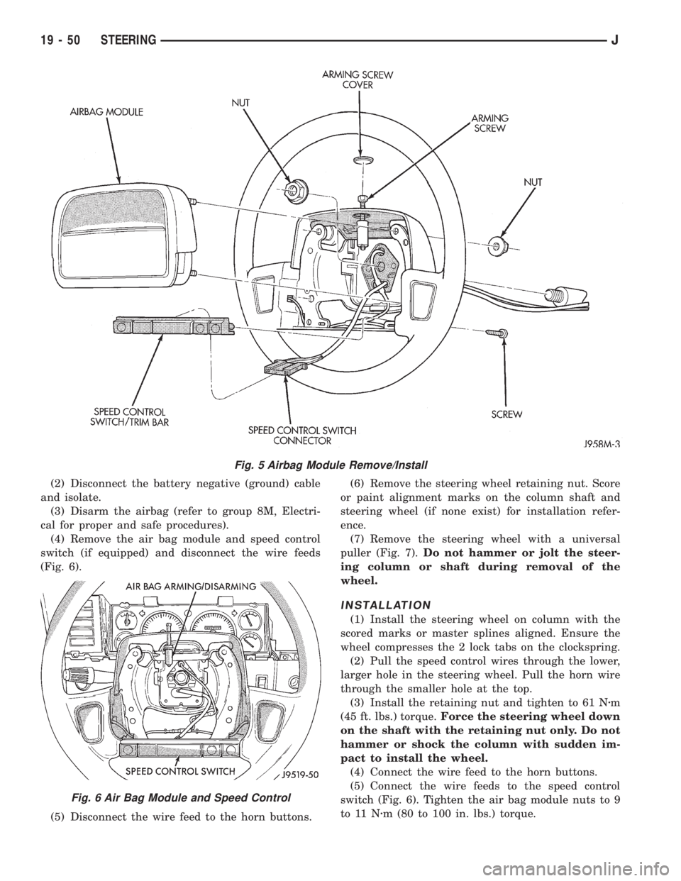
(4) Remove the air bag module and speed control
switch (if equipped) and disconnect the wire feeds
(Fig. 6).
(5) Disconnect the wire feed to the horn buttons.(6) Remove the steering wheel retaining nut. Score
or paint alignment marks on the column shaft and
steering wheel (if none exist) for installation refer-
ence.
(7) Remove the steering wheel with a universal
puller (Fig. 7).Do not hammer or jolt the steer-
ing column or shaft during removal of the
wheel.
INSTALLATION
(1) Install the steering wheel on column with the
scored marks or master splines aligned. Ensure the
wheel compresses the 2 lock tabs on the clockspring.
(2) Pull the speed control wires through the lower,
larger hole in the steering wheel. Pull the horn wire
through the smaller hole at the top.
(3) Install the retaining nut and tighten to 61 Nzm
(45 ft. lbs.) torque.Force the steering wheel down
on the shaft with the retaining nut only. Do not
hammer or shock the column with sudden im-
pact to install the wheel.
(4) Connect the wire feed to the horn buttons.
(5) Connect the wire feeds to the speed control
switch (Fig. 6). Tighten the air bag module nuts to 9
to 11 Nzm (80 to 100 in. lbs.) torque.
Fig. 5 Airbag Module Remove/Install
Fig. 6 Air Bag Module and Speed Control
19 - 50 STEERINGJ
Page 1535 of 2158
CLOCKSPRING
WARNING: BEFORE SERVICING AIR BAG SYSTEM,
REMOVE AND ISOLATE BATTERY NEGATIVE (-) CA-
BLE (GROUND) FROM VEHICLE BATTERY. WHEN
AN UNDEPLOYED AIR BAG ASSEMBLY IS TO BE
REMOVED FROM THE STEERING WHEEL, DISCON-
NECT THE BATTERY GROUND CABLE AND ISO-
LATE.
REMOVAL
(1) Place the front wheels in the straight ahead po-
sition before starting the repair.
(2) Disconnect battery negative cable and isolate.
(3) Remove the steering wheel and air bag, refer to
Steering Wheel Removal.
(4) Remove upper and lower steering column
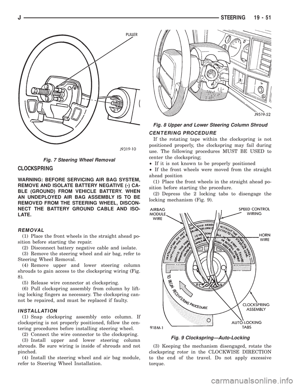
shrouds to gain access to the clockspring wiring (Fig.
8).
(5) Release wire connector at clockspring.
(6) Pull clockspring assembly from column by lift-
ing locking fingers as necessary. The clockspring can-
not be repaired, and must be replaced if faulty.
INSTALLATION
(1) Snap clockspring assembly onto column. If
clockspring is not properly positioned, follow the cen-
tering procedures before installing steering wheel.
(2) Connect the wire connector to the clockspring.
(3) Install upper and lower steering column
shrouds. Be sure wiring is inside of shrouds and not
pinched.
(4) Install the steering wheel and air bag module,
refer to Steering Wheel Installation.
CENTERING PROCEDURE
If the rotating tape within the clockspring is not
positioned properly, the clockspring may fail during
use. The following procedures MUST BE USED to
center the clockspring;
²If it is not known to be properly positioned
²If the front wheels were moved from the straight
ahead position
(1) Place the front wheels in the straight ahead po-
sition before starting the procedure.
(2) Depress the 2 locking tabs to disengage the
locking mechanism (Fig. 9).
(3) Keeping the mechanism disengaged, rotate the
clockspring rotor in the CLOCKWISE DIRECTION
to the end of the travel. Do not apply excessive
torque.
Fig. 7 Steering Wheel Removal
Fig. 8 Upper and Lower Steering Column Shroud
Fig. 9 ClockspringÐAuto-Locking
JSTEERING 19 - 51
Page 1537 of 2158
(14) Remove the Interlock cable from the steering
column. Refer to Automatic Transmission Shifter/Ig-
nition Interlock in this group.
(15) Remove the column. Use care to avoid damag-
ing the paint or trim.
INSTALLATION
CAUTION: Bumping, jolting and hammering on the
steering column shaft and gear shift tube must be
avoided during all service procedures.
(1) With the front wheels in the straight ahead po-
sition. Align and install the column to coupler.Do
not apply force at the top of the steering col-
umn shaft.(2) Ensure the ground clip is on the left spacer slot
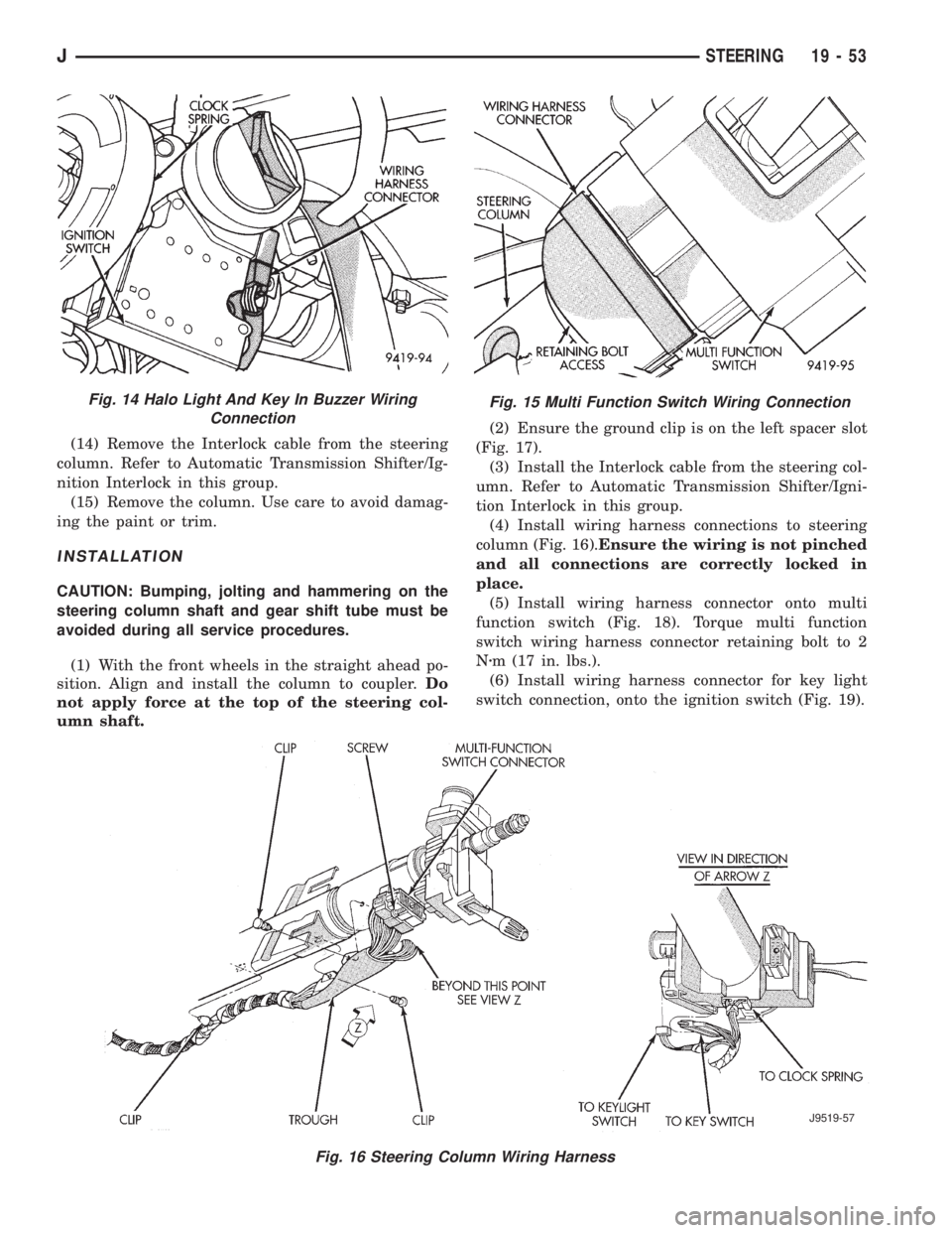
(Fig. 17).
(3) Install the Interlock cable from the steering col-
umn. Refer to Automatic Transmission Shifter/Igni-
tion Interlock in this group.
(4) Install wiring harness connections to steering
column (Fig. 16).Ensure the wiring is not pinched
and all connections are correctly locked in
place.
(5) Install wiring harness connector onto multi
function switch (Fig. 18). Torque multi function
switch wiring harness connector retaining bolt to 2
Nzm (17 in. lbs.).
(6) Install wiring harness connector for key light
switch connection, onto the ignition switch (Fig. 19).
Fig. 15 Multi Function Switch Wiring Connection
Fig. 16 Steering Column Wiring Harness
J9519-57
Fig. 14 Halo Light And Key In Buzzer Wiring
Connection
JSTEERING 19 - 53
Page 1538 of 2158
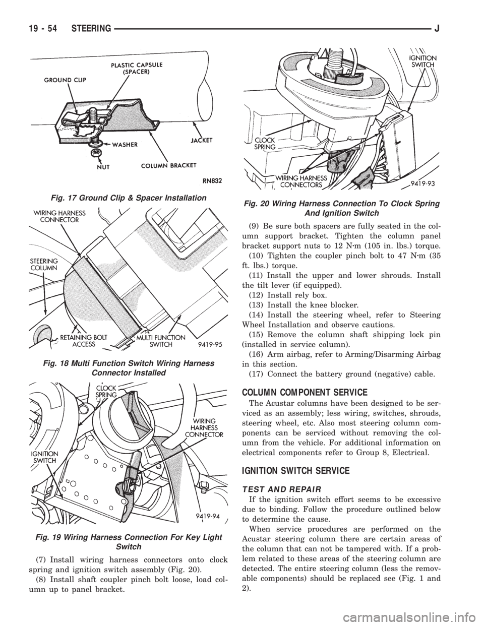
(7) Install wiring harness connectors onto clock
spring and ignition switch assembly (Fig. 20).
(8) Install shaft coupler pinch bolt loose, load col-
umn up to panel bracket.(9) Be sure both spacers are fully seated in the col-
umn support bracket. Tighten the column panel
bracket support nuts to 12 Nzm (105 in. lbs.) torque.
(10) Tighten the coupler pinch bolt to 47 Nzm (35
ft. lbs.) torque.
(11) Install the upper and lower shrouds. Install
the tilt lever (if equipped).
(12) Install rely box.
(13) Install the knee blocker.
(14) Install the steering wheel, refer to Steering
Wheel Installation and observe cautions.
(15) Remove the column shaft shipping lock pin
(installed in service column).
(16) Arm airbag, refer to Arming/Disarming Airbag
in this section.
(17) Connect the battery ground (negative) cable.
COLUMN COMPONENT SERVICE
The Acustar columns have been designed to be ser-
viced as an assembly; less wiring, switches, shrouds,
steering wheel, etc. Also most steering column com-
ponents can be serviced without removing the col-
umn from the vehicle. For additional information on
electrical components refer to Group 8, Electrical.
IGNITION SWITCH SERVICE
TEST AND REPAIR
If the ignition switch effort seems to be excessive
due to binding. Follow the procedure outlined below
to determine the cause.
When service procedures are performed on the
Acustar steering column there are certain areas of
the column that can not be tampered with. If a prob-
lem related to these areas of the steering column are
detected. The entire steering column (less the remov-
able components) should be replaced see (Fig. 1 and
2).
Fig. 17 Ground Clip & Spacer Installation
Fig. 18 Multi Function Switch Wiring Harness
Connector Installed
Fig. 19 Wiring Harness Connection For Key Light
Switch
Fig. 20 Wiring Harness Connection To Clock Spring
And Ignition Switch
19 - 54 STEERINGJ