1995 JEEP XJ oil change
[x] Cancel search: oil changePage 114 of 2158

MODEL 35 AXLE
INDEX
page page
Axle Shaft............................... 16
Axle Shaft Seal and Bearing................. 17
Backlash and Contact Pattern Analysis......... 27
Cleaning/Inspection........................ 20
Differential Assembly....................... 21
Differential Disassembly.................... 18
Differential Measurement and Installation........ 25
Differential Removal....................... 18
Drive Axle Assembly ReplacementÐXJ Vehicles . . 14Drive Axle Assembly ReplacementÐYJ Vehicles . . 14
Final Assembly........................... 29
General Information....................... 13
Lubricant Change......................... 13
Lubricant Specifications..................... 13
Pinion Gear Depth Information............... 21
Pinion Measurement and Assembly............ 22
Pinion Removal/Disassembly................. 19
Pinion Shaft Seal Replacement............... 15
GENERAL INFORMATION
The Model 35 housing has an iron center casting
(differential housing) with axle shaft tubes extending
from either side. The tubes are pressed into and
welded to the differential housing to form a one-piece
axle housing.
The integral type housing, hypoid gear design has
the centerline of the pinion set below the centerline
of the ring gear.
The axle has a vent hose to relieve internal pres-
sure caused by lubricant vaporization and internal
expansion.
The axles are equipped with semi-floating axle
shafts, meaning that loads are supported by the axle
shaft and bearings. The axle shafts are retained by
C-clips in the differential side gears.
The cover provides a means for servicing the differ-
ential without removing the axle.
Axles may be equipped with drum or disc brakes.
The axles that are equipped with ABS brake have a
tone ring pressed on the axle shaft. Use care when
removing axle shafts as NOT to damage the tone
wheel or the sensor.
The Model 35 axle has the assembly part number
and gear ratio listed on a tag. The tag is attached to
the housing cover. Build date identification codes are
stamped on the axle shaft tube cover side.
The differential case is a one-piece design. The dif-
ferential pinion mate shaft is retained with a
threaded roll pin. Differential bearing preload and
ring gear backlash is adjusted by the use of spacer
shims. Pinion bearing preload is set and maintained
by the use of a collapsible spacer.
For complete drive axle assembly removal
and installation refer to Drive Axle Assembly
Replacement in this Group.
LUBRICANT SPECIFICATIONS
Multi-purpose, hypoid gear lubricant should be
used for Model 35 axle. The lubricant should haveMIL-L-2105C and API GL 5 quality specifications.
MOPAR Hypoid Gear Lubricant conforms to both of
these specifications.
²Lubricant for Model 35 axle is a thermally stable
SAE 80W-90 gear lubricant.
²Lubricant for Model 35 axle with Trailer Tow is
SAE 75W-140 SYNTHETIC gear lubricant.
²Trac-Lok differentials add 4 oz. of friction modifier.
²Lubricant quantity is 1.66 L (3.50 pts.).
Refer to Group 0, Lubrication and Maintenance for
additional information.
CAUTION: If axle is submerged in water, lubricant
must be replaced immediately to avoid possible
premature axle failure.
LUBRICANT CHANGE
The gear lubricant will drain quicker if the vehicle
has been recently driven.
(1) Raise and support the vehicle.
(2) Remove the lubricant fill hole plug from the dif-
ferential housing cover.
(3) Remove the differential housing cover and
drain the lubricant from the housing.
(4) Clean the housing cavity with a flushing oil,
light engine oil or lint free cloth.Do not use water,
steam, kerosene or gasoline for cleaning.
(5) Remove the sealant from the housing and cover
surfaces.
(6) Apply a bead of MOPARtSilicone Rubber Seal-
ant to the housing cover (Fig. 1).Allow the sealant
to cure for a few minutes.
Install the housing cover within 5 minutes af-
ter applying the sealant. If not installed the
sealant must be removed and another bead ap-
plied.
(7) Install the cover and any identification tag.
Tighten the cover bolts to 41 Nzm (30 ft. lbs.) torque.
(8) Refill differential with Mopar Hypoid Gear Lu-
bricant to bottom of the fill plug hole.
JREAR SUSPENSION AND AXLES 3 - 13
Page 132 of 2158

LUBRICANT SPECIFICATIONS
Multi-purpose, hypoid gear lubricant should be
used in the 8 1/4 inch axle. The lubricant should
have MIL-L-2105C and API GL 5 quality specifica-
tions. MOPARtHypoid Gear Lubricant conforms to
both of these specifications.
²The factory installed lubricant for the 8 1/4 inch
rear axle is SAE 80W 90 gear lubricant.
²The factory installed lubricant quantity is 6762
fluid oz.
CAUTION: Overfilling the differential can result in
lubricant foaming and overheating.
Refer to Group 0, Lubrication and Maintenance for
additional information.
CAUTION: If axle is submerged in water, lubricant
must be replaced immediately to avoid possible
premature axle failure.
DRIVE AXLE ASSEMBLY REPLACEMENTÐXJ
VEHICLES
REMOVAL
(1) Raise the vehicle. Position support stands un-
der the frame rails slightly in front the springs.
(2) Remove the rear wheels.
(3) Mark the drive shaft yoke and axle pinion yoke
for alignment reference. Disconnect the drive shaft
from the axle.
(4) Disconnect the axle vent hose.
(5) Disconnect the parking brake cables at the
equalizer or backing plate.
(6) Disconnect the shock absorbers from the axle
brackets.
(7) Disconnect the brake hose at the axle junction
block.Do not disconnect the wheel cylinder tub-
ing fittings.
(8) If equipped, disconnect ABS wiring connections
at the axle.
(9) Support the axle with a hydraulic jack under
the differential.
(10) Remove the spring U-bolts from the plate
brackets.
(11) Lower the jack enough to remove the axle.
INSTALLATION
CAUTION: Suspension components with rubber
bushings should be tightened with the vehicle at
normal height. It is important to have the springs
supporting the weight of the vehicle when the fas-
teners are torqued. If springs are not at their normal
ride position, vehicle ride comfort could be affected
and premature bushing wear may occur. Rubber
bushings must never be lubricated.(1) Support the axle on a hydraulic jack under the
differential. Position the axle under the vehicle.
(2) Raise the axle and align the spring center bolts
with the locating holes in the axle pads and plate
brackets.
(3) Install the spring U-bolts through the plate
brackets and tighten to 70 Nzm (52 ft. lbs.) torque.
(4) Install ABS wiring connections (if equipped) at
the axle.
(5) Connect the brake hose at the axle junction
block.
(6) Install the shock absorbers to the axle brackets
and tighten to 62 Nzm (46 ft. lbs.) torque.
(7) Connect the parking brake cables at the equal-
izer or backing plate.
(8) Connect the vent hose to the tube fitting.
(9) Align the reference marks and connect the
drive shaft to the axle yoke. Tighten the U-joint
clamp bolts to 19 Nzm (14 ft. lbs.) torque.
(10) Check differential lubricant and add if neces-
sary.
(11) Install the wheel and tire.
(12) Bleed the brakes.
(13) Remove the supports and lower the vehicle.
LUBRICANT CHANGE
The gear lubricant will drain quicker if the vehicle
has been recently driven.
(1) Raise and support the vehicle.
(2) Remove the lubricant fill hole plug from the dif-
ferential housing cover.
(3) Remove the differential housing cover and
drain the lubricant from the housing.
(4) Clean the housing cavity with a flushing oil,
light engine oil or lint free cloth.Do not use water,
steam, kerosene or gasoline for cleaning.
(5) Remove the sealant from the housing and cover
surfaces. Use solvent to clean the mating surfaces.
(6) Apply a bead of MOPARtSilicone Rubber Seal-
ant to the housing cover (Fig. 2). Allow the sealant to
cure for a few minutes.
Install the housing cover within 5 minutes after
applying the sealant. If not installed the sealant
must be removed and another bead applied.
(7) Install the cover and any identification tag.
Tighten the cover bolts in a criss-cross pattern to 47
Nzm (35 ft. lbs.) torque.
(8) Refill the differential with Mopar Hypoid Gear
Lubricant 13 mm (1/2 in.) below the fill plug hole.
With Trac-Lok differentials, add a container of Mopar
Hypoid Gear Lubricant Additive.
CAUTION: Overfilling the differential can result in
lubricant foaming and overheating.
(9) Install the fill hole plug and lower the vehicle.
JREAR SUSPENSION AND AXLES 3 - 31
Page 154 of 2158

ABS SYSTEM CHANGES
A different master cylinder, power brake booster,
and HCU are used in the 1995 Jeep ABS system.
The master cylinder reservoir has a single filler cap
and is no longer interconnected with the HCU. The
new HCU has built-in accumulators. The pedal travel
sensor has been eliminated and a new dual dia-
phragm power brake booster is used.
BRAKE FLUID/LUBRICANTS/CLEANING SOLVENTS
Recommended fluid for all Jeep vehicles is Mopar
DOT 3 brake fluid, or an equivalent meeting SAE
J1703 and DOT 3 standards.
Use Mopar Multi Mileage grease to lubricate drum
brake pivot pins and rear brakeshoe contact points
on the support plates. Use GE 661, or Dow 111 sili-
cone grease on caliper bushings and mounting bolts.
Use fresh brake fluid or Mopar brake cleaner to
clean or flush brake system components. These are
the only cleaning materials recommended.
CAUTION: Never use gasoline, kerosene, methyl or
isopropyl alcohol, paint thinner, or any fluid con-
taining mineral oil to clean brake parts. These fluids
damage rubber cups and seals. If system contami-
nation is suspected, check the fluid for dirt, discol-
oration, or separation into distinct layers. Drain and
flush the system with new brake fluid if contamina-
tion is suspected.
JEEP BODY CODE LETTERS
The body/model identification code letters for Jeep
vehicles are as follows:²Code letters XJ: Cherokee
²Code letters YJ: Wrangler/YJ
The code letters are used throughout this group to
simplify model identification and component applica-
tion.
BRAKE SAFETY PRECAUTIONS
WARNING: ALTHOUGH FACTORY INSTALLED
BRAKELINING ON JEEP VEHICLES IS MADE FROM
ASBESTOS FREE MATERIALS, SOME AFTER MAR-
KET BRAKELINING MAY CONTAIN ASBESTOS. THIS
SHOULD BE TAKEN INTO ACCOUNT WHEN RE-
PAIRING A VEHICLE WITH PRIOR BRAKE SERVICE.
WEAR A RESPIRATOR WHEN CLEANING BRAKE
COMPONENTS AS ASBESTOS FIBERS CAN BE A
HEALTH HAZARD. NEVER CLEAN WHEEL BRAKE
COMPONENTS WITH COMPRESSED AIR. USE A
VACUUM CLEANER SPECIFICALLY DESIGNED FOR
REMOVING BRAKE DUST. IF A VACUUM CLEANER
IS NOT AVAILABLE, CLEAN THE PARTS WITH WA-
TER DAMPENED SHOP RAGS. DO NOT CREATE
DUST BY SANDING BRAKELINING. DISPOSE OF
ALL DUST AND DIRT SUSPECTED OF CONTAINING
ASBESTOS FIBERS IN SEALED BAGS OR CON-
TAINERS. FOLLOW ALL SAFETY PRACTICES REC-
OMMENDED BY THE OCCUPATIONAL SAFETY AND
HEALTH ADMINISTRATION (OSHA) AND THE ENVI-
RONMENTAL PROTECTION AGENCY (EPA), FOR
HANDLING AND DISPOSAL OF ASBESTOS.
5 - 2 BRAKESJ
Page 159 of 2158
fied. This causes pull to switch direction in favor of
the brake unit that is functioning normally.
When diagnosing a change in pull condition, re-
member that pull will return to the original direction
if the dragging brake unit is allowed to cool down
(and is not seriously damaged).
REAR BRAKE GRAB
Rear grab (or pull) is usually caused by contami-
nated lining, bent or binding shoes and support
plates, or improperly assembled components. This is
particularly true when only one rear wheel is in-
volved. However, when both rear wheels are affected,
the master cylinder could be at fault.
BRAKES DO NOT HOLD AFTER DRIVING THROUGH
DEEP WATER PUDDLES
This condition is caused by water soaked lining. If
the lining is only wet, it can be dried by driving with
the brakes lightly applied for a mile or two. However,
if the lining is both wet and dirty, disassembly and
cleaning will be necessary.
CONTAMINATED BRAKELINING
Brakelining contaminated by water is salvageable.
The lining can either be air dried or dried using heat.
In cases where brakelining is contaminated by oil,
grease, or brake fluid, the lining should be replaced.
Replacement is especially necessary when fluids/lu-
bricants have actually soaked into the lining mate-
rial. However, grease or dirt that gets onto the lining
surface (from handling) during brake repairs, can be
cleaned off. Spray the lining surface clean with Mo-
par brake cleaner.
BRAKE FLUID CONTAMINATION
There are two basic causes of brake fluid contami-
nation. The first involves allowing dirt, debris, or
other materials to enter the cylinder reservoirs when
the cover is off. The second involves adding non-rec-
ommended fluids to the cylinder reservoirs.
Brake fluid contaminated with only dirt, or debris
usually retains a normal appearance. In some cases,
the foreign material will remain suspended in the
fluid and be visible. The fluid and foreign material
can be removed from the reservoir with a suction gun
but only if the brakes have not been applied. If the
brakes are applied after contamination, system flush-
ing will be required. The master cylinder may also
have to be disassembled, cleaned and the piston seals
replaced. Foreign material lodged in the reservoir
compensator/return ports can cause brake drag by re-
stricting fluid return after brake application.
Brake fluid contaminated by a non-recommended
fluid may appear discolored, milky, oily looking, or
foamy. However, remember that brake fluid will
darken in time and occasionally be cloudy in appear-ance. These are normal conditions and should not be
mistaken for contamination.
If some type of oil has been added to the system,
the fluid will separate into distinct layers. To verify
this, drain off a sample with a clean suction gun.
Then pour the sample into a glass container and ob-
serve fluid action. If the fluid separates into distinct
layers, it is definitely contaminated.
The only real correction for contamination by non-
recommended fluid is to flush the entire hydraulic
system and replace all the seals.
BRAKE NOISE
Squeak/Squeal
Factory installed brakelining is made from as-
bestos free materials. These materials have dif-
ferent operating characteristics than previous
lining material. Under certain conditions, as-
bestos free lining may generate some squeak,
groan or chirp noise. This noise is considered
normal and does not indicate a problem. The
only time inspection is necessary, is when noise
becomes constant or when grinding, scraping
noises occur.
Constant brake squeak or squeal may be due to lin-
ings that are wet or contaminated with brake fluid,
grease, or oil. Glazed linings, rotors/drums with hard
spots, and dirt/foreign material embedded in the
brake lining also cause squeak. Loud squeak, squeal,
scraping, or grinding sounds are a sign of severely
worn brake lining. If the lining has worn completely
through in spots, metal-to-metal contact occurs.
Thump/Clunk
Thumping or clunk noises during braking are fre-
quentlynotcaused by brake components. In many
cases, such noises are caused by loose or damaged
steering, suspension, or engine components. However,
calipers that bind on the slide surfaces can generate
a thump or clunk noise. In addition, worn out, im-
properly adjusted, or improperly assembled rear
brakeshoes can also produce a thump noise.
Chatter/Shudder
Brake chatter, or shudder is usually caused by
loose or worn components, or glazed/burnt lining. Ro-
tors with hard spots can also contribute to chatter.
Additional causes of chatter are out of tolerance ro-
tors, brake lining not securely attached to the shoes,
loose wheel bearings and contaminated brake lining.
WHEEL AND TIRE PROBLEMS
Some conditions attributed to brake components
may actually be caused by a wheel or tire problem.
A damaged wheel can cause shudder, vibration and
pull. A worn or damaged tire can also cause pull.
Severely worn tires with very little tread left can
JSERVICE BRAKE DIAGNOSIS 5 - 7
Page 328 of 2158

groups of four pulses generated on 2.5L 4-cylinder
engines. There are 3 groups of four pulses generated
on 4.0L 6-cylinder engines.
The trailing edge of the fourth notch, which causes
the pulse, is four degrees before top dead center
(TDC) of the corresponding piston.
The engine will not operate if the PCM does not re-
ceive a crankshaft position sensor input.
For component testing, refer to the Diagnostics/Ser-
vice Procedures section of this group.
For removal and installation of this sensor, refer to
the Component Removal/Installation section of this
group.
DISTRIBUTORS
All engines are equipped with a camshaft driven
mechanical distributor containing a shaft driven dis-
tributor rotor. All distributors are equipped with an
internal camshaft position (fuel sync) sensor. This
sensor provides fuel injection synchronization and
cylinder identification.
The distributors on both the 2.5L 4-cylinder and
the 4.0L-6 cylinder engines do not have built in cen-
trifugal or vacuum assisted advance. Base ignition
timing and all timing advance is controlled by the
powertrain control module (PCM). Because ignition
timing is controlled by the PCM,base ignition tim-
ing is not adjustable on any of these engines.
The distributor is locked in place by a fork with a
slot located on the distributor housing base. The dis-
tributor holddown clamp bolt passes through this slot
when installed. Because the distributor position is
locked when installed, its rotational position can not
be changed.Do not attempt to modify the dis-tributor housing to get distributor rotation.
Distributor position will have no effect on igni-
tion timing. The position of the distributor will
determine fuel synchronization only.
All distributors contain an internal oil seal that
prevents oil from entering the distributor housing.
The seal is not serviceable.
Distributor removal and installation procedures
have changed for the 1995 model year. Refer to Dis-
tributor in the Component Removal/Installation sec-
tion of this group.
IGNITION COIL
Battery voltage is supplied to the ignition coil pos-
itive terminal from the ASD relay.
The powertrain control module (PCM) opens and
closes the ignition coil ground circuit for ignition coil
operation. This is done through pin/cavity number 19
of the PCM 60-way connector.
Base ignition timing is not adjustable.By con-
trolling the coil ground circuit, the PCM is able to set
the base timing and adjust the ignition timing ad-
vance. This is done to meet changing engine operat-
ing conditions.
The ignition coil is not oil filled. The windings are
embedded in an epoxy compound. This provides heat
and vibration resistance that allows the ignition coil
to be mounted on the engine.
On the 2.5L 4-cylinder engine, the ignition coil is
mounted to a bracket on the side of the engine (to
the rear of the distributor).
Fig. 9 Sensor OperationÐ4.0L 6-Cyl. EngineÐAll
Except YJ Models With Automatic Transmission
Fig. 10 Sensor OperationÐ4.0L 6-Cyl. EngineÐYJ
Models With Automatic Transmission
8D - 4 IGNITION SYSTEMSJ
Page 337 of 2158
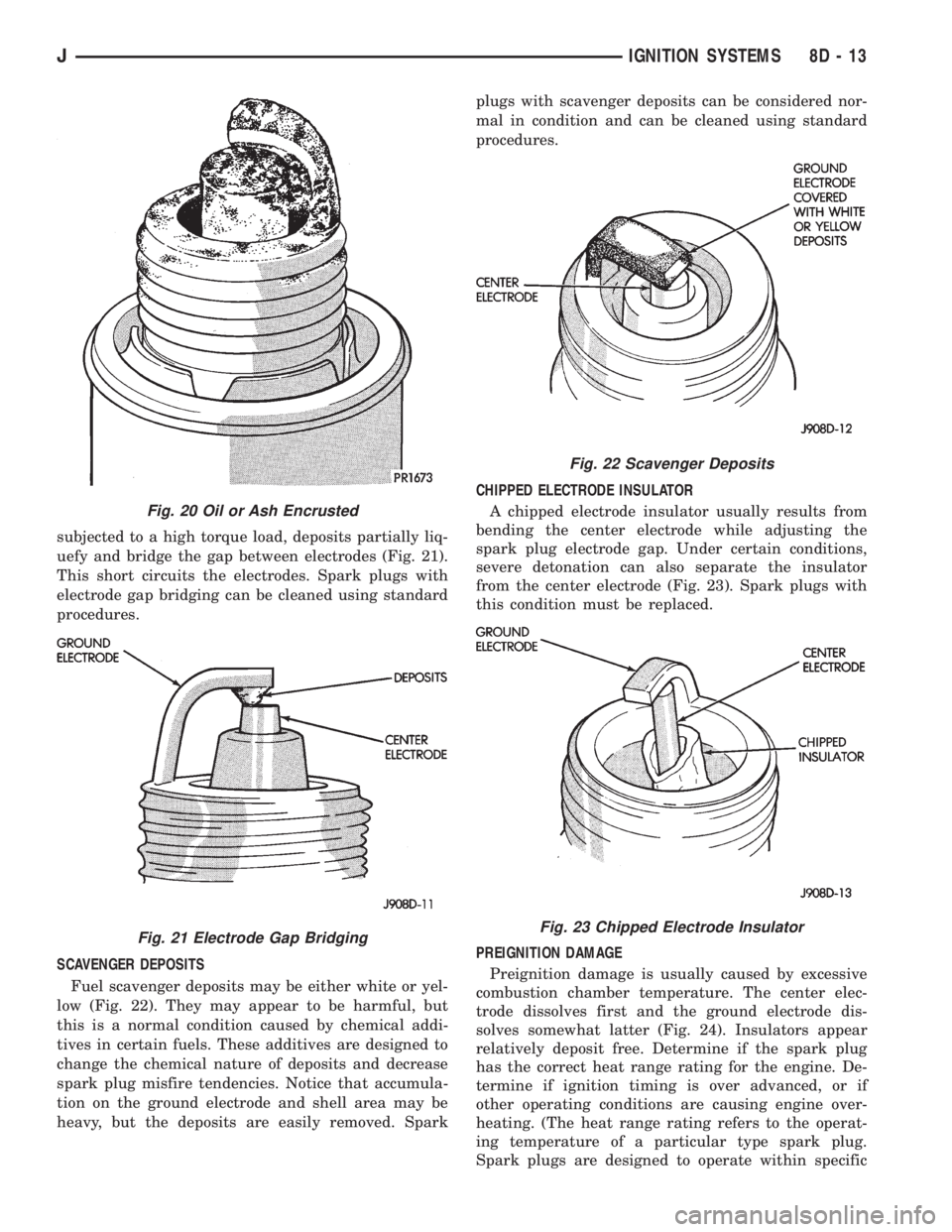
subjected to a high torque load, deposits partially liq-
uefy and bridge the gap between electrodes (Fig. 21).
This short circuits the electrodes. Spark plugs with
electrode gap bridging can be cleaned using standard
procedures.
SCAVENGER DEPOSITS
Fuel scavenger deposits may be either white or yel-
low (Fig. 22). They may appear to be harmful, but
this is a normal condition caused by chemical addi-
tives in certain fuels. These additives are designed to
change the chemical nature of deposits and decrease
spark plug misfire tendencies. Notice that accumula-
tion on the ground electrode and shell area may be
heavy, but the deposits are easily removed. Sparkplugs with scavenger deposits can be considered nor-
mal in condition and can be cleaned using standard
procedures.
CHIPPED ELECTRODE INSULATOR
A chipped electrode insulator usually results from
bending the center electrode while adjusting the
spark plug electrode gap. Under certain conditions,
severe detonation can also separate the insulator
from the center electrode (Fig. 23). Spark plugs with
this condition must be replaced.
PREIGNITION DAMAGE
Preignition damage is usually caused by excessive
combustion chamber temperature. The center elec-
trode dissolves first and the ground electrode dis-
solves somewhat latter (Fig. 24). Insulators appear
relatively deposit free. Determine if the spark plug
has the correct heat range rating for the engine. De-
termine if ignition timing is over advanced, or if
other operating conditions are causing engine over-
heating. (The heat range rating refers to the operat-
ing temperature of a particular type spark plug.
Spark plugs are designed to operate within specific
Fig. 20 Oil or Ash Encrusted
Fig. 21 Electrode Gap Bridging
Fig. 22 Scavenger Deposits
Fig. 23 Chipped Electrode Insulator
JIGNITION SYSTEMS 8D - 13
Page 348 of 2158
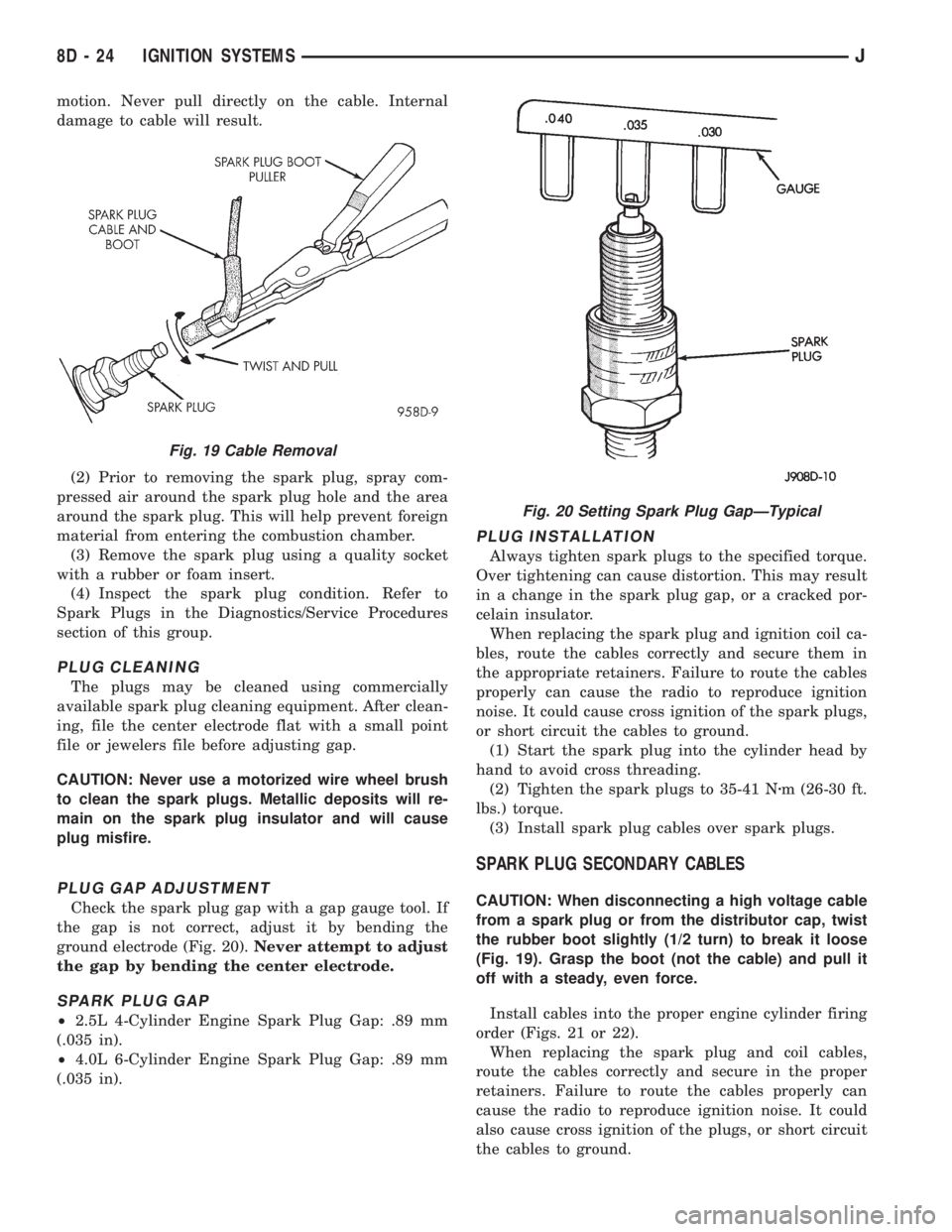
motion. Never pull directly on the cable. Internal
damage to cable will result.
(2) Prior to removing the spark plug, spray com-
pressed air around the spark plug hole and the area
around the spark plug. This will help prevent foreign
material from entering the combustion chamber.
(3) Remove the spark plug using a quality socket
with a rubber or foam insert.
(4) Inspect the spark plug condition. Refer to
Spark Plugs in the Diagnostics/Service Procedures
section of this group.
PLUG CLEANING
The plugs may be cleaned using commercially
available spark plug cleaning equipment. After clean-
ing, file the center electrode flat with a small point
file or jewelers file before adjusting gap.
CAUTION: Never use a motorized wire wheel brush
to clean the spark plugs. Metallic deposits will re-
main on the spark plug insulator and will cause
plug misfire.
PLUG GAP ADJUSTMENT
Check the spark plug gap with a gap gauge tool. If
the gap is not correct, adjust it by bending the
ground electrode (Fig. 20).Never attempt to adjust
the gap by bending the center electrode.
SPARK PLUG GAP
²2.5L 4-Cylinder Engine Spark Plug Gap: .89 mm
(.035 in).
²4.0L 6-Cylinder Engine Spark Plug Gap: .89 mm
(.035 in).
PLUG INSTALLATION
Always tighten spark plugs to the specified torque.
Over tightening can cause distortion. This may result
in a change in the spark plug gap, or a cracked por-
celain insulator.
When replacing the spark plug and ignition coil ca-
bles, route the cables correctly and secure them in
the appropriate retainers. Failure to route the cables
properly can cause the radio to reproduce ignition
noise. It could cause cross ignition of the spark plugs,
or short circuit the cables to ground.
(1) Start the spark plug into the cylinder head by
hand to avoid cross threading.
(2) Tighten the spark plugs to 35-41 Nzm (26-30 ft.
lbs.) torque.
(3) Install spark plug cables over spark plugs.
SPARK PLUG SECONDARY CABLES
CAUTION: When disconnecting a high voltage cable
from a spark plug or from the distributor cap, twist
the rubber boot slightly (1/2 turn) to break it loose
(Fig. 19). Grasp the boot (not the cable) and pull it
off with a steady, even force.
Install cables into the proper engine cylinder firing
order (Figs. 21 or 22).
When replacing the spark plug and coil cables,
route the cables correctly and secure in the proper
retainers. Failure to route the cables properly can
cause the radio to reproduce ignition noise. It could
also cause cross ignition of the plugs, or short circuit
the cables to ground.
Fig. 19 Cable Removal
Fig. 20 Setting Spark Plug GapÐTypical
8D - 24 IGNITION SYSTEMSJ
Page 358 of 2158

The high-line cluster includes the following gauges:
²coolant temperature gauge
²fuel gauge
²oil pressure gauge
²speedometer/odometer
²tachometer
²trip odometer
²voltmeter.
The high-line cluster includes provisions for the fol-
lowing indicator lamps:
²anti-lock brake system lamp
²brake warning lamp
²four-wheel drive indicator lamps
²headlamp high beam indicator lamp
²low fuel warning lamp
²low washer fluid warning lamp
²malfunction indicator (Check Engine) lamp
²seat belt reminder lamp
²turn signal indicator lamps
²upshift indicator lamp.
GAUGES
With the ignition switch in the ON or START posi-
tion, voltage is supplied to all gauges through the in-
strument cluster gauge area printed circuit. With the
ignition switch in the OFF position, voltage is not
supplied to the gauges. A gauge pointer may remain
within the gauge scale after the ignition switch is
OFF. However, the gauges do not accurately indicate
any vehicle condition unless the ignition switch is
ON.
All gauges except the odometer are air core mag-
netic units. Two fixed electromagnetic coils are lo-
cated within the gauge. These coils are wrapped at
right angles to each other around a movable perma-
nent magnet. The movable magnet is suspended
within the coils on one end of a shaft. The gauge nee-
dle is attached to the other end of the shaft.
One of the coils has a fixed current flowing through
it to maintain a constant magnetic field strength.
Current flow through the second coil changes, which
causes changes in its magnetic field strength. The
current flowing through the second coil can be
changed by:
²a variable resistor-type sending unit (fuel level,
coolant temperature, or oil pressure)
²changes in electrical system voltage (voltmeter)
²electronic control circuitry (speedometer/odometer,
tachometer).
The gauge needle moves as the movable permanent
magnet aligns itself to the changing magnetic fields
created around it by the electromagnets.
COOLANT TEMPERATURE GAUGE
The coolant temperature gauge gives an indication
of engine coolant temperature. The coolant tempera-
ture sending unit is a thermistor that changes elec-
trical resistance with changes in engine coolanttemperature. High sending unit resistance causes
low coolant temperature readings. Low resistance
causes high coolant temperature readings.
The gauge will read at the high end of the scale
when the ignition switch is turned to the START po-
sition. This is caused by the bulb test circuit wiring
provision. The same wiring is used for the high-line
cluster with a coolant temperature gauge and the
low-line cluster with a coolant temperature warning
lamp. Sending unit resistance values are shown in a
chart in Specifications.
FUEL GAUGE
The fuel gauge gives an indication of the level of
fuel in the fuel tank. The fuel gauge sending unit has
a float attached to a swing-arm in the fuel tank. The
float moves up or down within the fuel tank as fuel
level changes. As the float moves, an electrical con-
tact on the swing-arm wipes across a resistor coil,
which changes sending unit resistance. High sending
unit resistance causes low fuel level readings. Low
resistance causes high fuel level readings. Sending
unit resistance values are shown in a chart in Spec-
ifications.
OIL PRESSURE GAUGE
The oil pressure gauge gives an indication of en-
gine oil pressure. The combination oil pressure send-
ing unit contains a flexible diaphragm. The
diaphragm moves in response to changes in engine
oil pressure. As the diaphragm moves, sending unit
resistance increases or decreases. High resistance on
the gauge side of the sending unit causes high oil
pressure readings. Low resistance causes low oil
pressure readings. Sending unit resistance values are
shown in a chart in Specifications.
SPEEDOMETER/ODOMETER
The speedometer/odometer gives an indication of
vehicle speed and travel distance. The speedometer
receives a vehicle speed pulse signal from the Vehicle
Speed Sensor (VSS). An electronic integrated circuit
contained within the speedometer reads and analyzes
the pulse signal. It then adjusts the ground path re-
sistance of one electromagnet in the gauge to control
needle movement. It also sends signals to an electric
stepper motor to control movement of the odometer
number rolls. Frequency values for the pulse signal
are shown in a chart in Specifications.
The VSS is mounted to an adapter near the trans-
mission (two-wheel drive) or transfer case (four-wheel
drive) output shaft. The sensor is driven through the
adapter by a speedometer pinion gear. The adapter
and pinion vary with transmission, transfer case,
axle ratio and tire size. Refer to Group 21 - Trans-
mission and Transfer Case for more information.
8E - 2 INSTRUMENT PANEL AND GAUGESÐXJJ