1995 JEEP XJ 4WD
[x] Cancel search: 4WDPage 45 of 2158
(11) Remove the support and lower the vehicle.
DRIVE SHAFTS
Lubricate at the intervals described in the Mainte-
nance Schedule section of this Group. Refer to Group
16, Propeller Shafts for proper service procedures.
CAUTION: It is very important that drive shafts be
lubricated at periodic intervals and that the speci-
fied type of lubricant be used. Failure to properly
lubricate could result in premature wear of drive
shaft components.
LUBRICANT SPECIFICATION
Use Mopar, Multi-purpose Grease or any lubricate
that is identified as NLGI GC-LB lubricant.
RUBBER AND PLASTIC HOSES/TUBING
The condition of underbody rubber hose and plastic
tubing should be inspected whenever underbody ser-
vice is performed.
Rubber hoses and plastic tubing should be re-
placed immediately if there is any evidence of
failure.
HOSE/TUBING INSPECTION
(1) Inspect all hose and tubing fittings for loose-
ness and corrosion. Inspect the rubber hoses for brit-
tleness and cracks. Thoroughly inspect the hose ends
(those that are slipped over nipple connectors) for
splits (Fig. 10, 11, 12, 13, 14, 15 and 16).
(2) Inspect the surface of hoses and tubing for heat
and mechanical damage. Hose and tubing located
close to an exhaust pipe should be given special at-
tention.
(3) Inspect the rubber hose routing to ensure that
the hoses do not contact any heat source, moving
component, etc., that would potentially cause heat or
mechanical damage.
(4) Inspect all the hose connections to ensure that
they are secure and there is no fluid leakage. Actual
dripping of hot fluid should be noted and the clamps
tightened in an attempt to stop the leakage before re-
placing the hose.
Fig. 10 Front Axle Vent Hose (4WD)ÐXJ Vehicles
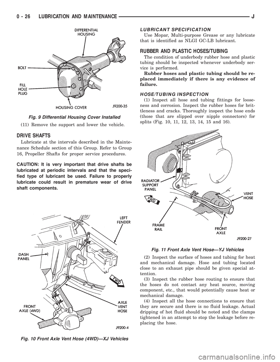
Fig. 9 Differential Housing Cover Installed
Fig. 11 Front Axle Vent HoseÐYJ Vehicles
0 - 26 LUBRICATION AND MAINTENANCEJ
Page 46 of 2158
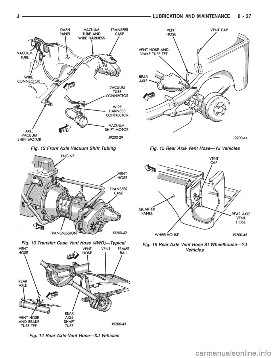
Fig. 12 Front Axle Vacuum Shift Tubing
Fig. 13 Transfer Case Vent Hose (4WD)ÐTypical
Fig. 14 Rear Axle Vent HoseÐXJ Vehicles
Fig. 15 Rear Axle Vent HoseÐYJ Vehicles
Fig. 16 Rear Axle Vent Hose At WheelhouseÐYJ
Vehicles
JLUBRICATION AND MAINTENANCE 0 - 27
Page 47 of 2158
CHASSIS AND BODY COMPONENTS
INDEX
page page
Body Components........................ 32
Chassis Component and Wheel Bearing
Lubricants............................. 28
Front Wheel Bearings...................... 28
Headlamps.............................. 33
Manual Steering Gear...................... 30Power Brake System....................... 30
Power Steering System..................... 29
Speedometer Cable....................... 33
Steering Linkage.......................... 28
Tires................................... 32
CHASSIS COMPONENT AND WHEEL BEARING
LUBRICANTS
The chassis component and wheel bearing lubri-
cants that are recommended for Jeep vehicles are
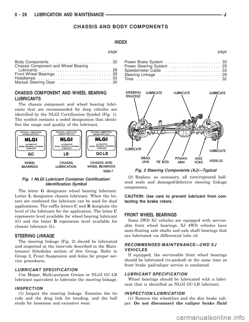
identified by the NLGI Certification Symbol (Fig. 1).
The symbol contains a coded designation that identi-
fies the usage and quality of the lubricant.
The letterGdesignates wheel bearing lubricant.
LetterLdesignates chassis lubricant. When the let-
ters are combined the lubricant can be used for dual
applications. The suffix lettersCandBdesignate the
level of the lubricant for the application. The letterC
represents level available for wheel bearing lubricant
(G) and the letterBrepresents level available for
chassis lubricant (L).
STEERING LINKAGE
The steering linkage (Fig. 2) should be lubricated
and inspected at the intervals described in the Main-
tenance Schedules section of this Group. Refer to
Group 2, Front Suspension and Axles for proper ser-
vice procedures.
LUBRICANT SPECIFICATION
Use Mopar, Multi-purpose Grease or NLGI GC-LB
lubricant equivalent to lubricate the steering linkage.
INSPECTION
(1) Inspect the steering linkage. Examine the tie
rods and the drag link for bending, and the ball
studs for looseness and excessive wear.(2) Replace, as necessary, all torn/ruptured ball-
stud seals and damaged/defective steering linkage
components.
CAUTION: Use care to prevent lubricant from con-
tacting the brake rotors.
FRONT WHEEL BEARINGS
Some 2WD XJ vehicles are equipped with service-
able front wheel bearings. XJ 4WD vehicles have
semi-floating axle shafts and axle shaft bearings that
are lubricated via differential lube oil.
RECOMMENDED MAINTENANCEÐ2WD XJ
VEHICLES
If equipped, the serviceable front wheel bearings
should be lubricated (re-packed) at the same time as
front brake pad/caliper service is conducted.
LUBRICANT SPECIFICATION
Wheel bearings should be lubricated with a lubri-
cant that is identified as NLGI GC-LB lubricant.
INSPECTION/LUBRICATION
(1) Remove the wheel/tire and the disc brake cali-
per.Do not disconnect the caliper brake fluid
Fig. 1 NLGI Lubricant Container Certification/
Identification Symbol
Fig. 2 Steering Components (XJ)ÐTypical
0 - 28 LUBRICATION AND MAINTENANCEJ
Page 53 of 2158
FRONT SUSPENSION AND AXLE
CONTENTS
page page
AXLE NOISE/VIBRATION DIAGNOSIS........ 18
AXLE SPECIFICATIONS................... 49
FRONT WHEEL ALIGNMENT................ 5
GENERAL INFORMATION.................. 1MODEL 30 AXLE AND TUBE AXLE (2WD).... 22
TORQUE SPECIFICATIONS................ 49
XJ FRONT SUSPENSION.................. 11
YJ FRONT SUSPENSION.................. 15
GENERAL INFORMATION
FRONT SUSPENSION
XJ VEHICLES
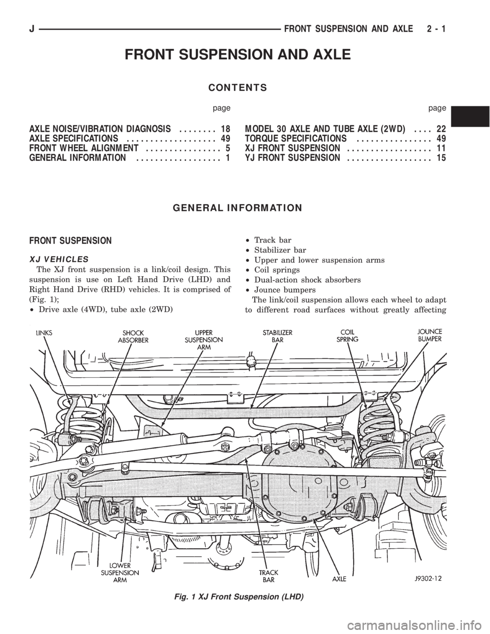
The XJ front suspension is a link/coil design. This
suspension is use on Left Hand Drive (LHD) and
Right Hand Drive (RHD) vehicles. It is comprised of
(Fig. 1);
²Drive axle (4WD), tube axle (2WD)²Track bar
²Stabilizer bar
²Upper and lower suspension arms
²Coil springs
²Dual-action shock absorbers
²Jounce bumpers
The link/coil suspension allows each wheel to adapt
to different road surfaces without greatly affecting
Fig. 1 XJ Front Suspension (LHD)
JFRONT SUSPENSION AND AXLE 2 - 1
Page 75 of 2158

CAUTION: If axle is submerged in water, lubricant
must be replaced immediately to avoid possible
premature axle failure.
LUBRICANT CHANGE
The gear lubricant will drain quicker if the vehicle
has been recently driven.
(1) Raise and support the vehicle.
(2) Remove the lubricant fill hole plug from the dif-
ferential housing cover.
(3) Remove the differential housing cover and
drain the lubricant from the housing.
(4) Clean the housing cavity with a flushing oil,
light engine oil or lint free cloth.Do not use water,
steam, kerosene or gasoline for cleaning.
(5) Remove the sealant from the housing and cover
surfaces. Use solvent to clean the mating surfaces.
(6) Apply a bead of MOPARtSilicone Rubber Seal-
ant to the housing cover (Fig. 1).Allow the sealant
to cure for a few minutes.
Install the housing cover within 5 minutes af-
ter applying the sealant. If not installed the
sealant must be removed and another bead ap-
plied.
(7) Install the cover and any identification tag.
Tighten the cover bolts in a criss-cross pattern to 41
Nzm (30 ft. lbs.) torque.
(8) Refill the differential with MOPARtHypoid
Gear Lubricant to bottom of the fill plug hole.
(9) Install the fill hole plug and lower the vehicle.
DRIVE AXLE ASSEMBLY REPLACEMENTÐXJ
VEHICLES
REMOVAL
(1) Raise the vehicle and position support stands
under the frame rails behind the lower suspension
arm frame brackets.
(2) Remove the front wheels.
(3) Remove the brake components and ABS brake
sensor (if equipped). Refer to Group 5ÐBrakes.
(4) On 4WD vehicles, disconnect the axle vent
hose.
(5) On 4WD vehicles, mark the drive shaft yoke
and axle pinion yoke for alignment reference. Discon-
nect the drive shaft from the axle.
(6) Disconnect the stabilizer bar link at the axle
bracket.
(7) Disconnect the shock absorbers from axle
bracket.
(8) Disconnect the track bar from the axle bracket.
(9) Disconnect the tie rod and drag link from the
steering knuckle. Disconnect the steering damper
from the axle bracket.
(10) Support the axle with a hydraulic jack under
the differential.
(11) Disconnect the upper and lower suspension
arms from the axle bracket.
(12) Lower the jack enough to remove the axle.
The coil springs will drop with the axle.
(13) Remove the coil springs from the axle bracket.
INSTALLATION
CAUTION: Suspension components with rubber
bushings should be tightened with the vehicle at
normal height. It is important to have the springs
supporting the weight of the vehicle when the fas-
teners are torqued. If springs are not at their normal
ride position, vehicle ride comfort could be affected
and premature bushing wear may occur. Rubber
bushings must never be lubricated.
(1) Install the springs and retainer clip. Tighten
the retainer bolts to 21 Nzm (16 ft. lbs.) torque.
(2) Support the axle on a hydraulic jack under the
differential. Position the axle under the vehicle.
(3) Raise the axle with a floor jack and align it
with the spring pads.
(4) Position the upper and lower suspension arm at
the axle bracket. Install bolts and nuts finger
tighten.
(5) Connect the track bar to the axle bracket and
install the bolt.Do not tighten at this time.
It is important that the springs support the
weight of the vehicle when the track bar is con-
nected. If springs are not at their usual posi-
tion, vehicle ride comfort could be affected.
Fig. 1 Typical Housing Cover With Sealant
JFRONT SUSPENSION AND AXLE 2 - 23
Page 76 of 2158

(6) Install the shock absorber and tighten the bolt
to 23 Nzm (17 ft. lbs.) torque.
(7) Install the stabilizer bar link to the axle
bracket. Tighten the nut to 95 Nzm (70 ft. lbs.)
torque.
(8) Install the drag link and tie rod to the steering
knuckles and tighten the nuts to 47 Nzm (35 ft. lbs.)
torque. Install the steering damper to the axle
bracket and tighten the nut to 75 Nzm (55 ft. lbs.)
torque.
(9) Install the brake components and ABS brake
sensor (if equipped). Refer to Group 5ÐBrakes.
(10) On 4WD vehicles, connect the vent hose to the
tube fitting.
(11) On 4WD vehicles, align the reference marks
and connect the drive shaft to the axle yoke. Tighten
the U-joint clamp bolts to 19 Nzm (14 ft. lbs.) torque.
(12) Check differential lubricant and add if neces-
sary.
(13) Install the wheel and tire assemblies.
(14) Remove the supports and lower the vehicle.
(15) Tighten the upper suspension arm nuts to 75
Nzm (55 ft. lbs.) torque. Tighten the lower suspension
arm nuts to 115 Nzm (85 ft. lbs.) torque.
(16) Tighten the track bar bolt at the axle bracket
to 100 Nzm (74 ft. lbs.) torque.
(17) Check the front wheel alignment.
DRIVE AXLE ASSEMBLY REPLACEMENTÐYJ
VEHICLES
REMOVAL
(1) Raise the vehicle and position support stands
under the frame rails behind the spring frame brack-
ets.
(2) Remove the front wheels.
(3) Remove the brake components and ABS brake
sensor (if equipped). Refer to Group 5ÐBrakes.
(4) Disconnect the axle vent hose and axle shift
motor vacuum harness.
(5) Mark the drive shaft yoke and axle pinion yoke
for alignment reference. Disconnect the drive shaft
from the axle.
(6) Disconnect the stabilizer bar link at the axle
bracket.
(7) Disconnect the shock absorbers from axle
bracket.
(8) Disconnect the track bar from the axle bracket.
(9) Disconnect the tie rod from the steering
knuckle. Disconnect the steering damper from the
axle bracket.
(10) Support the axle with a hydraulic jack under
the differential. Raise the axle just enough to relieve
the axle weight from the springs.
(11) Remove the spring U-bolts from the plate
brackets.(12) Loosen BUT DO NOT REMOVE the bolts that
attach the spring rear pivot at the frame rail brack-
ets. This will allow the springs to pivot without bind-
ing on the bushings.
(13) Disconnect shackle from the springs and lower
the springs to the surface.
(14) Lower the jack enough to remove the axle.
INSTALLATION
CAUTION: Suspension components with rubber
bushings should be tightened with the vehicle at
normal height. It is important to have the springs
supporting the weight of the vehicle when the fas-
teners are torqued. If springs are not at their normal
ride position, vehicle ride comfort could be affected
and premature bushing wear may occur. Rubber
bushings must never be lubricated.
(1) Support the axle on a hydraulic jack under the
differential. Position the axle under the vehicle.
(2) Raise the springs and install the spring shackle
bolts.Do not tighten at this time.
(3) Lower the axle and align the spring center
bolts with the locating holes in the axle pads and
plate brackets.
(4) Install the spring U-bolts through the plate
brackets and tighten to 122 Nzm (90 ft. lbs.) torque.
(5) Connect the track bar to the axle bracket and
install the bolt.Do not tighten at this time.
It is important that the springs support the
weight of the vehicle when the track bar is con-
nected. If springs are not at their usual posi-
tion, the vehicle ride comfort could be affected.
(6) Install the shock absorber and tighten the nut
to 61 Nzm (45 ft. lbs.) torque.
(7) Install the stabilizer bar link to the axle
bracket. Tighten the nut to 61 Nzm (45 ft. lbs.)
torque.
(8) Install the tie rod to the steering knuckles and
tighten the nuts to 47 Nzm (35 ft. lbs.) torque. Install
the steering damper to the axle bracket and tighten
the bolt to 75 Nzm (55 ft. lbs.) torque.
(9) Install the brake components and ABS brake
sensor (if equipped). Refer to Group 5ÐBrakes.
(10) Connect the vent hose to the tube fitting and
axle shift motor vacuum harness.
(11) Align the reference marks and connect the
drive shaft to the axle yoke. Tighten the U-joint
clamp bolts to 19 Nzm (14 ft. lbs.) torque.
(12) Check differential lubricant and add if neces-
sary.
(13) Install the wheel and tire assemblies.
(15) Remove the supports and lower the vehicle.
(16) Tighten the spring rear pivot bolt/nut to 142
Nzm (105 ft. lbs.) torque. Tighten the spring shackle
bolt/nut to 135 Nzm (100 ft. lbs.) torque.
2 - 24 FRONT SUSPENSION AND AXLEJ
Page 359 of 2158
TACHOMETER
The tachometer gives an indication of engine speed
in Revolutions-Per-Minute (RPM). With the engine
running, the tachometer receives an engine speed
pulse signal from the Powertrain Control Module
(PCM). An electronic integrated circuit contained
within the tachometer reads and analyzes the pulse
signal. It then adjusts the ground path resistance of
one electromagnet in the gauge to control needle
movement. Frequency values for the pulse signal are
shown in a chart in Specifications.
TRIP ODOMETER
The trip odometer is driven by the same electronic
integrated circuit as the speedometer/odometer. How-
ever, by depressing the trip odometer reset knob on
the face of the speedometer, the trip odometer can be
reset to zero. The trip odometer is serviced only as a
part of the speedometer/odometer gauge assembly.
VOLTMETER
The voltmeter is connected in parallel with the bat-
tery. With the ignition switch ON, the voltmeter in-
dicates battery or generator output voltage,
whichever is greater.
INDICATOR LAMPS
Indicator lamps are located in two areas within the
cluster. Each of these areas is served by a separate
printed circuit and cluster connector. Those lamps in
the gauge area of the cluster share the gauge area
printed circuit and cluster connector A. Those lamps
in the tell-tale area of the cluster use the tell-tale
printed circuit and cluster (tell-tale) connector B.
Up to ten indicator lamps can be found in the tell-
tale area of the cluster. These lamps are arranged in
five stacked rows with two lamps in each row, located
to the driver's side of the main cluster.
ANTI-LOCK BRAKE SYSTEM LAMP
The Anti-Lock Brake System (ABS) lamp is
switched to ground by the ABS module. The module
lights the lamp when the ignition switch is turned to
the START position as a bulb test. The lamp will
stay on for 3 to 5 seconds after vehicle start-up to in-
dicate a system self-test is in process. If the lamp re-
mains on after start-up, or comes on and stays on
while driving, it may indicate that the ABS module
has detected a system malfunction or that the system
has become inoperative. Refer to Group 5 - Brakes
for more information.
BRAKE WARNING LAMP
The brake warning lamp warns the driver that the
parking brake is applied or that the pressures in the
two halves of the split brake hydraulic system are
unequal. With the ignition switch turned ON, batteryvoltage is supplied to one side of the indicator bulb. A
ground path for the bulb is provided by 3 switches.
The bulb will light when:
²the brake warning switch is closed (indicating un-
equal brake system hydraulic pressures possibly due
to brake fluid leakage)
²the ignition switch is in the START position (bulb
test)
²the parking brake switch is closed (parking brake
is applied).
Refer to Group 5 - Brakes for more information.
COOLANT TEMPERATURE WARNING LAMP
The coolant temperature warning lamp lights
whenever engine coolant temperature is too high.
Battery voltage is supplied to one side of the indica-
tor bulb when the ignition switch is turned ON. The
normally open coolant temperature switch is con-
nected to the other side of the bulb. When coolant
temperature is too high, the switch closes. This pro-
vides a ground path for the indicator bulb, which
causes it to light. The lamp is also grounded and
should light with the ignition switch in the START
position as a bulb test.
FOUR-WHEEL DRIVE INDICATOR LAMPS
PART TIME
On vehicles with Command-Trac 4WD, the Part
Time lamp lights when the transfer case is engaged
in the 4H or 4L position. On vehicles with Selec-Trac
4WD, the Part Time lamp lights when the transfer
case is engaged in the4X4PARTTIME or 4 LO po-
sition. Voltage is supplied to one side of the indicator
bulb. A switch in the transfer case is connected to the
other side of the indicator bulb. When the switch is
closed, a path to ground is provided and the indicator
bulb lights.
FULL TIME
The Full Time lamp is only operational on vehicles
equipped with Selec-Trac 4WD. The Full Time lamp
lights when the transfer case is engaged in the4X4
Full Time position. Voltage is supplied to one side of
the indicator bulb. A switch in the transfer case is
connected to the other side of the indicator bulb.
When the switch is closed, a path to ground is pro-
vided and the indicator bulb lights.
GENERATOR WARNING LAMP
The generator warning lamp lights with the igni-
tion switch turned to ON, but should go out when-
ever the engine is running. If the lamp comes on and
stays on while the engine is running, it indicates
that a charging system malfunction exists. One side
of the bulb is connected to ignition-switched battery
feed. The other side of the bulb is switched to ground
by the Powertrain Control Module (PCM).
JINSTRUMENT PANEL AND GAUGESÐXJ 8E - 3
Page 369 of 2158
Connect battery negative cable and turn ignition
switch to ON. Lamp should light. If OK, repair open
circuit to brake warning switch. If not OK, replace
bulb.
(5) Turn ignition switch to OFF and remove
jumper wire. Disconnect battery negative cable.
Check for continuity between cavity A (cavity B -
RHD) of brake warning switch connector and a good
ground with ignition switch in START position.
There should be continuity. If not OK, go to next
step.
(6) Turn ignition switch to OFF and remove
jumper wire. Disconnect battery negative cable. Un-
plug ignition switch connector. Check for continuity
between ignition switch connector cavity 3 and a
good ground. There should be no continuity. If OK, go
to next step. If not OK, repair short circuit between
ignition switch and brake warning switch connectors
as required.
(7) Check for continuity between ignition switch
connector cavity 3 and brake warning switch connec-
tor cavity A (cavity B - RHD). There should be conti-
nuity. If OK, go to next step. If not OK, repair open
circuit as required.
(8) Check for continuity between metal steering
column jacket and a good ground. There should be
continuity. If OK, go to next step. If not OK, refer to
Group 19 - Steering to check steering column ground
clip installation.
(9) Turn ignition switch to START position and
hold there. Check for continuity between terminal 3
of ignition switch and a good ground. There should
be continuity. If not OK, replace ignition switch.
(10) Unplug brake warning switch connector.
Check for continuity between parking brake switch
connector and a good ground. There should be no
continuity. If OK, go to next step. If not OK, repair
short circuit as required.
(11) Check for continuity between parking brake
switch connector and cavity B (cavity A - RHD) of
brake warning switch connector. There should be
continuity. If OK, replace parking brake switch. If
not OK, repair open circuit to brake warning switch
as required.
COOLANT TEMPERATURE WARNING LAMP
The diagnosis found here addresses an inoperative
lamp condition. If the problem being diagnosed is re-
lated to lamp accuracy, be certain to confirm that
problem is with lamp and not with cooling system
performance. Actual engine coolant temperature
should be checked with a test gauge or thermometer
before proceeding with lamp diagnosis. Refer to
Group 7 - Cooling System for more information.
(1) Turn ignition switch to START position. Lamp
should light. If OK, go to next step. If not OK, go to
step 3.(2) Turn ignition switch to ON. Disconnect coolant
temperature switch connector (Fig. 1). Jump switch
connector to ground. Lamp should light. If OK, re-
place switch. If not OK, go to next step.
(3) Turn ignition switch to OFF. Disconnect battery
negative cable. Unplug coolant temperature switch
connector. Remove instrument cluster bezel and clus-
ter assembly. Disconnect cluster connector A and
probe cavity A1. Check for continuity to a good
ground. There should be no continuity. If OK, go to
next step. If not OK, repair short circuit to coolant
temperature switch or ignition switch as required.
(4) Connect cluster connector A to cluster. Install a
jumper wire from cavity A1 of cluster connector A to
a good ground. Connect battery negative cable and
turn ignition switch to ON. Lamp should light. If OK,
repair open circuit to coolant temperature switch or
ignition switch as required. If not OK, replace bulb.
FOUR-WHEEL DRIVE INDICATOR LAMPS
(1) Apply parking brake, start engine, vehicle in
4WD Lock or 4WD.
(2) Unplug switch and touch harness side of wire
to ground. Lamp should light. If OK, check switch
operation, replace if bad. If bulb is OK, repair open
to indicator.
GENERATOR WARNING LAMP
(1) Disconnect battery negative cable and unplug
PCM connector. Install a jumper wire between cavity
36 of PCM connector (Fig. 5) and a good ground. Con-
nect battery negative cable and turn ignition switch
to ON. Lamp should light. Unplug jumper wire and
lamp should go off. If OK, refer to Powertrain Diag-
nostic Procedures to check PCM. If not OK, go to
next step.
(2) Turn ignition switch to OFF and disconnect
battery negative cable. Remove instrument cluster
bezel and cluster assembly. Install a jumper wire be-
tween cavity B8 of cluster connector A and a good
ground. Connect battery negative cable and turn ig-
nition switch to ON. Lamp should light. If OK, go to
next step. If not OK, replace bulb.
(3) Turn ignition switch to OFF and disconnect
battery negative cable. Unplug cluster connector A.
Probe cavity B8 of cluster connector A and check for
continuity to a good ground. There should be no con-
tinuity. If OK, go to next step. If not OK, repair short
circuit as required.
(4) Check for continuity between cavity B8 of clus-
ter connector A and cavity 36 of PCM connector.
There should be continuity. If not OK, repair open
circuit as required.
HEADLAMP HIGH BEAM INDICATOR LAMP
(1) Check that headlamp high beams are func-
tional. If OK, go to next step. If not OK, refer to
Group 8L - Lamps for diagnosis of headlamp system.
JINSTRUMENT PANEL AND GAUGESÐXJ 8E - 13