1995 JEEP XJ 4WD
[x] Cancel search: 4WDPage 389 of 2158
(9) Turn ignition switch to START position and
hold there. Check for continuity between terminal for
circuit G11 of ignition switch and a good ground.
There should be continuity. If not OK, replace igni-
tion switch.
(10) Unplug brake warning switch connector.
Check for continuity between parking brake switch
connector and a good ground. There should be no
continuity. If OK, go to next step. If not OK, repair
short circuit as required.
(11) Check for continuity between parking brake
switch connector and brake warning switch connector
cavity for circuit G11. There should be continuity. If
OK, replace parking brake switch. If not OK, repair
open circuit to brake warning switch as required.
FOUR-WHEEL DRIVE INDICATOR LAMP
(1) Apply parking brake, start engine, vehicle in
4WD Lock or 4WD.
(2) Unplug switch and touch harness side of wire
to ground. Lamp should light. If OK, check switch
operation, replace if bad. If bulb is OK, repair open
to indicator.
HEADLAMP HIGH BEAM INDICATOR LAMP
(1) Check that headlamp high beams are func-
tional. If OK, go to next step. If not OK, refer to
Group 8L - Lamps for diagnosis of headlamp system.
(2) Disconnect battery negative cable. Remove left
instrument cluster bezel and main cluster assembly.
Unplug cluster connector. Connect battery negative
cable. Turn headlamps on and select high beam.
Check for battery voltage at cavity 17 of cluster con-
nector. If OK, replace indicator bulb. If not OK, re-
pair circuit to headlamp dimmer switch as required.
MALFUNCTION INDICATOR LAMP
The diagnosis found here addresses an inoperative
lamp condition. If the lamp comes on and stays on
with engine running, refer to Group 14 - Fuel System
for diagnosis. If no fuel or emission system problem
is found, the following procedure will help locate a
short or open in the lamp circuit.
(1) Disconnect battery negative cable. Unplug PCM
connector. Install a jumper wire from cavity 32 of
PCM connector (Fig. 5) to a good ground. Connect
battery negative cable. Turn ignition switch to ON.
Lamp should light. Remove jumper wire and lamp
should go OFF. If OK, refer to Powertrain Diagnostic
Procedures to check PCM. If not OK, go to next step.
(2) Turn ignition switch to OFF. Disconnect battery
negative cable. Remove left instrument cluster bezel
and main cluster assembly. Install a jumper wire
from cavity 2 of cluster connector to a good ground.
Connect battery negative cable. Turn ignition switch
to ON. Lamp should light. If OK, go to next step. If
not OK, replace bulb.(3) Turn ignition switch to OFF. Disconnect battery
negative cable. Unplug cluster connector. Check for
continuity between cavity 2 of cluster connector and
a good ground. There should be no continuity. If OK,
go to next step. If not OK, repair short circuit to
PCM as required.
(4) Check continuity between cavity 2 of cluster
connector and cavity 32 of PCM connector. There
should be continuity. If not OK, repair open circuit to
PCM as required.
SEAT BELT REMINDER LAMP
(1) Refer to Group 8U - Chime/Buzzer Warning
Systems to check chime/buzzer module operation. If
OK, go to next step. If not OK, replace chime/buzzer
module.
(2) Disconnect battery negative cable. Remove left
instrument cluster bezel and main cluster assembly.
Unplug cluster connector. Check for continuity be-
tween cavity 20 of cluster connector and a good
ground. There should be continuity. If OK, plug clus-
ter connector back into cluster and go to next step. If
not OK, repair open circuit to ground as required.
(3) Connect battery negative cable. Install a
jumper wire between a 12-volt battery feed and cav-
ity 16 of cluster connector. Lamp should light. If OK,
go to next step. If not OK, replace bulb.
(4) Disconnect battery negative cable. Unplug
chime/buzzer module from fuseblock module. Unplug
cluster connector. Check for continuity between cav-
ity 16 of cluster connector and a good ground. There
should be no continuity. If OK, go to next step. If not
OK, repair short circuit to chime/buzzer module as
required.
(5) Check continuity between cavity 16 of cluster
connector and cavity for terminal A3 of chime/buzzer
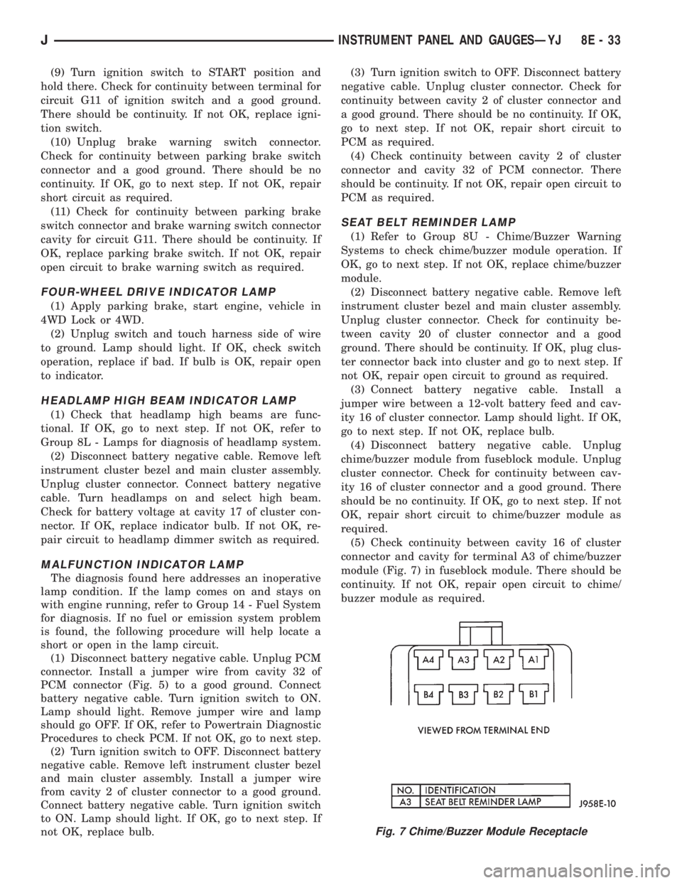
module (Fig. 7) in fuseblock module. There should be
continuity. If not OK, repair open circuit to chime/
buzzer module as required.
Fig. 7 Chime/Buzzer Module Receptacle
JINSTRUMENT PANEL AND GAUGESÐYJ 8E - 33
Page 609 of 2158

TRANSMISSION CONTROLS
UPSHIFT LAMP
On vehicles equipped with a manual transmission,
the PCM grounds the up-shift lamp on circuit K54.
Circuit K54 connects to cavity 54 of the PCM.
FOUR-WHEEL DRIVE (4WD) SWITCH
When the 4WD switch closes, circuit Z1 provides
ground for the 4WD indicator lamp in the instrument
cluster. Circuit F87 connects to the instrument clus-
ter and supplies battery voltage to the 4WD indicator
lamp. Circuit 107 connects the indicator lamp to the
4WD switch. Circuit 106 connects the lamp to the in-
strument cluster and circuit F87.
TRANSMISSION CONTROL MODULEÐ4.0L
ENGINE ONLY
Vehicles equipped with the 4.0L engine have elec-
tronically controlled solenoids in the automatic trans-
mission valve body.
The Transmission Control Module (TCM) receives
inputs from the Throttle Position Sensor (TPS) on
circuit K22 and the stop lamp switch on circuit K29.
Circuit K4 connects to the TCM to provide ground for
the TPS signal. The TCM receives the transmission
output speed sensor signal on circuit T505. Circuit
A14 from fuse 2 in the Power Distribution Center
supplies battery voltage to the TCM. Circuit Z12 pro-
vides ground for the TCM.
The TCM powers the S1 solenoid on circuit T510,
the S2 solenoid on circuit T509, and the S3 solenoid
on circuit T508. Circuit Z12 provides ground for the
S1, S2, and S3 solenoids.
TORQUE CONVERTER CLUTCH (TCC) SOLENOID
AND RELAYÐ2.5L ENGINE ONLY
The TCC solenoid is only used on 2.5L engines
with the three-speed automatic transmissions. The
Powertrain Control Module (PCM) operates the TCC
solenoid by energizing the TCC relay.
Circuit T17 from fuse 12 in the Power Distribution
Center (PDC) supplies voltage to the coil and contact
sides of the TCC relay. When the PCM provides a
ground path on circuit K54 for the coil side of the re-
lay, the relay contacts close.
When the relay contacts close, they connect circuit
T17 with circuit T22. Circuit T22 supplies battery
voltage to the case grounded TCC solenoid. Circuit
K54 connects to PCM cavity 54.
HELPFUL INFORMATION
²In the RUN or START position, the ignition switch
connects circuit A1 from fuse 6 in the PDC to circuit
A21.
DIAGRAM INDEX
Component Page
4-WD Indicator Lamp......................8W-31-4
4-WD Indicator Switch.....................8W-31-4
Back-Up Lamp Switch.....................8W-31-3
Fuse 2 (PDC)...........................8W-31-4
Fuse 6 (PDC).........................8W-31-2, 3
Fuse 11 (PDC)..........................8W-31-3
Fuse 12 (PDC)..........................8W-31-2
Ignition Switch........................8W-31-2, 3
Powertrain Control Module..................8W-31-2
Park/Neutral Position Switch.................8W-31-3
TCC Relay.............................8W-31-2
TCC Solenoid...........................8W-31-2
Transmission Control Module.................8W-31-2
J8W-31 TRANSMISSION CONTROLSÐXJ VEHICLES 8W - 31 - 1
Page 627 of 2158
CHARGING SYSTEM INDICATOR LAMP
The Powertrain Control Module (PCM) illuminates
the charging system indicator lamp by providing
ground for the lamp on circuit G12. Circuit G12 con-
nects to cavity 36 of the PCM. Circuit F87 supplies
battery voltage to the lamp.
FOUR-WHEEL DRIVE (4WD) SWITCH
When the 4WD switch closes, circuit Z1 provides
ground for the 4WD indicator lamp in the instrument
cluster. Circuit F87 connects to the instrument clus-
ter and supplies battery voltage to the 4WD indicator
lamp. Circuit 107 connects the indicator lamp to the
4WD switch. Circuit 106 connects the lamp to the in-
strument cluster and circuit F87.
CLUSTER GROUND
Circuit Z1 from the instrument cluster left connec-
tor provides ground for the illumination lamps and
indicator lamps.
HELPFUL INFORMATION
²If the warning lamps don't operate, check fuse 14
in the fuse block.
²If the indicator lamps and illumination lamps
don't operate, check fuse 13 in the fuse block.
²Inspect the ground at the instrument panel lower
right reinforcement support.
DIAGRAM INDEX
Component Page
4WD Switch............................8W-40-9
4WD Indicator Lamp......................8W-40-9
ABS Control Module......................8W-40-9
Brake Warning Switch.....................8W-40-10
Chime/Buzzer Module......................8W-40-8
Daytime Running Lamps Module.............8W-40-5, 6
Engine Coolant Temperature Sending Unit.........8W-40-6
Engine Oil Pressure Sending Unit..............8W-40-6
Fuse 3 (PDC)...........................8W-40-8
Fuse 5 (PDC)...........................8W-40-4
Fuse 6 (PDC).........................8W-40-4, 8
Fuse 11 (PDC)..........................8W-40-8
Fuse 16 (PDC)..........................8W-40-8
Fuse 9 (Fuse Block).......................8W-40-8
Fuse 15 (Fuse Block)......................8W-40-4
Fuse 17 (Fuse Block)....................8W-40-4, 8
Fuse 19 (Fuse Block)......................8W-40-4
Headlamp Switch.......................8W-40-4, 5
Headlamp Delay Module....................8W-40-8
Headlamp Dimmer Switch...................8W-40-5
Ignition Switch......................8W-40-4, 8, 10
Instrument Cluster......................8W-40-4, 5
Low Washer Fluid Lamp Switch...............8W-40-8
Park Brake Switch.......................8W-40-10
Powertrain Control Module..................8W-40-6
Remote Keyless Entry Module................8W-40-8
Telltale Connector (Instrument Cluster).....8W-40-7 thru 10
J8W-40 INSTRUMENT CLUSTERÐXJ VEHICLES 8W - 40 - 3
Page 786 of 2158
Connector # Color Location Fig.
C226......BK ...Left Kick Panel
C227......BK ...OnI.P.Right of Steering Column . . .10
C228......BK ...Left Side of Steering Column.....14
C229......BK ...TopofBrake Pedal Arm.........13
C230......BK ...Left Side of I.P...............12
C231......BK ...Center of I.P.................10
C232......GY ...Left Side of I.P...............12
C233......BK ...Left Side of I.P...............12
C234......BK ...Rear of I.P. Cluster............10
C235......NAT...Rear of I.P. Cluster............10
C236......BK ...OnI.P.Right of Steering Column . . .10
C237......BK ...OnI.P.Right of Steering Column . . .10
C238......BK ...OnI.P.Left of Steering Column....10
C239......RD ...OnI.P.Left of Steering Column....10
C240......BK ...Left Front Door..............17
C241......BK ...Center of I.P.
C242......BK ...Center Bottom of I.P..........9,11
C243......BK ...Center Left of I.P.
C301......DG ...Behind Left Kick Panel
C302......BK ...Near Floor Console
C303......BK ...Bottom Right of Drivers Seat . . .15, 23
C304......BK ...Bottom of Drivers Sear.........15
C305......BK ...Behind Right Kick Panel........17
C306......BK ...Left B Pillar................18
C307......BK ...Near Fuel Tank..............15
C308......BK ...InLiftgate.................24
C309......BK ...Under Rear of Roof Liner........20
C310......BK ...Left Rear Quarter Panel.........20
C311......BK ...Left Rear Quarter Panel.........20
C312......BK ...Left Rear Quarter Panel.........20
C313......BK ...InLiftgate.................24
C314......NAT...InLeft Rear Door.............18
C315......BK ...InLeft Rear Door.............18
C316......RD ...InLeft Rear Door.............18
C317......BK ...Behind Left Kick Panel.......15, 17
C318......RD ...Behind Left Kick Panel.......15, 17
C319......BK ...Under Floor Console...........15
C320......GY ...Under Right Rear Seat.........18
C321......BK ...Behind Right Kick Panel........17
C322......DG ...AtDome Lamp
C323......BK ...InLiftgate.................24
C324......BK ...Right Rear Quarter Panel........20
C325......NAT...InRight Rear Door............18
C326......BK ...InRight Rear Door............18
C327......BK ...InRight Rear Door............18
C328......BK ...InRight B Pillar..............18
C329......BK ...InRight Front Door...........17
C331......BK ...InRight Front Door...........17
C332......BK ...InRight Front Door...........17
C333......BK ...InRight Front Door...........17
C334......BK ...InRight Front Door...........17
C335......BK ...InLeft Front Door............17
C336......BK ...InLeft Front Door............17
C338......BK ...InLeft Front Door............17
C339......BK ...InLeft Front Door............17
C340......BK ...InLeft Front Door............17
C341......BK ...InLeft Front Door............17Connector # Color Location Fig.
C342......BK ...Front Center of Roof Liner.......16
C343......BK ...Behind Overhead Console.......16
C344......BK ...Behind Doom Lamp...........16
C345......BK ...Inleft Rear Corner of Vehicle.....20
C346......BK ...Left Rear Quarter Panel.........20
C347......BK ...Left Rear Quarter Panel.........20
C348......BK ...Left Rear Quarter Panel.........20
C349......BK ...Left Rear Quarter Panel.........20
C350......BK ...InLiftgate.................24
C351......BK ...Left Rear Quarter Panel.........22
C352......BK ...Floor Pan, Near Drivers Seat
C353......BK ...InLiftgate.................25
C354......BK ...Below Left Rear Seat..........19
C355......RD ...Below Left Rear Seat..........19
C356......BK ...Below Left Rear Seat..........19
C357......BK ...OnTransmission.............21
C358......GN ...InLiftgate.................24
C401......BK ...Behind PRNDL..............15
C402......BK ...InFloor Console
C403......BK ...Rear of Radio...............11
C404......BK ...Rear of Transmission (2WD)......21
C404......BK ...Rear of Transfer Case (4WD).....21
C405......BK ...Behind Cargo Lamp...........20
C406......YL ...InLiftgate.................24
C407......BK ...OnTransfer Case.............21
C408......BK ...Side of Transmission
C409......BK ...Right of Radiator............1,3
C410......BK ...InLeft Rear Door
C411......BK ...InLeft Front Door
C412......BK ...InRight Door
C413......BK ...InRight Rear Door
C414......BK ...OnTransfer Case.............21
C415......BK ...Near Underhood Lamp
C416......BK ...Behind Lens
C417......BK ...Behind Lens
C418......YL ...Behind Lens
C419......YL ...Behind Lens
C420......BK ...Behind Lens
C421......BK ...Behind Lens
C422......BK ...Behind Lens
C423......BK ...Behind Lens
C424......BK ...Side of Drivers Seat...........23
C425......BK ...Below Drivers Seat............23
C426......BK ...Behind Lens................25
C427......BK ...Behind Lens................25
C428......BK ...AtAshReceiver..............12
C429......BK ...InLiftgate.................24
C430......BK ...InLiftgate.................24
G101............Near Battery.................5
G102............Near Battery.................5
G103............Right Front Side of Engine, Behind
Generator.................5
G104............Left Fender Side Shield, Behind
PCM ..................1,2
G105............Left Fender Side Shield, Behind
PCM ..................1,2
G106............Right Rear of Engine..........6,7
G107............Right Rear of Engine..........6,7
8W - 90 - 2 8W-90 CONNECTOR LOCATIONSÐXJ VEHICLESJ
Page 873 of 2158

TRANSMISSION CONTROLS
FOUR-WHEEL DRIVE (4WD) SWITCH
When the 4WD switch closes, circuit Z1 provides
ground for the 4WD indicator lamp in the instrument
cluster. Circuit F87 connects to the instrument clus-
ter and supplies battery voltage to the 4WD indicator
lamp. Circuit 107 connects the indicator lamp to the
4WD switch. Circuit 106 connects the lamp to the in-
strument cluster and circuit F87.
TRANSMISSION COMFORT SWITCH
Circuit T17 from fuse 12 in the Power Distribution
Center (PDC) supplies battery voltage to the trans-
mission comfort switch. Circuit Z1 provides ground
for the switch. Circuit T177 Connects the switch to
the Transmission Control Module (TCM).
TRANSMISSION CONTROL MODULE
Vehicles equipped with the 4.0L engine have elec-
tronically controlled solenoids in the automatic trans-
mission valve body.
The transmission control module (TCM) receives
inputs from the throttle position sensor (TPS) on cir-
cuit K22 and the stop lamp switch on circuit K29.
Circuit K4 connects to the TCM to provide ground for
the TPS signal.
The TCM receives the transmission output speed
sensor signal on circuit 505. Circuit A14 from fuse 2
in the Power Distribution Center (PDC) supplies bat-
tery voltage to the TCM. Circuit T17 from fuse 12 in
the PDC also connects to the TCM. Circuit Z12 pro-
vides ground for the TCM.The TCM powers the S1 solenoid on circuit 510,
the S2 solenoid on circuit 509, and the S3 solenoid on
circuit 508. Circuit Z12 provides ground for the S1,
S2, and S3 solenoids.
Circuits 506 and 507 from the Park/Neutral posi-
tion switch connect to the TCM. Circuits 506 and 507
tell the TCM what drive range the transmission is in.
DATA LINK CONNECTOR
Circuit 137 from the TCM connects to the data link
connector. Circuit F39 from fuse 5 in the PDC sup-
plies power to the data link connector. Circuit Z12
provides ground for the data link connector.
DIAGRAM INDEX
Component Page
ABS Data Link Connector...................8W-31-3
4-WD Indicator Lamp......................8W-31-4
4-WD Indicator Switch.....................8W-31-4
Fuse 2 (PDC)...........................8W-31-4
Fuse 6 (PDC).........................8W-31-2, 3
Fuse 11 (PDC)..........................8W-31-3
Fuse 12 (PDC)..........................8W-31-2
Ignition Switch........................8W-31-2, 3
Park/Neutral Position Switch.................8W-31-3
Telltale Connector (Instrument Cluster)...........8W-31-4
Transmission Comfort Switch.................8W-31-2
Transmission Control Module.............8W-31-2, 3, 4
Transmission Valve Body Solenoids.............8W-31-4
J8W-31 TRANSMISSION CONTROLSÐXJ-RHD 8W - 31 - 1
Page 890 of 2158
LOW WASHER FLUID WARNING LAMP
Circuit G29 connects the low washer fluid switch to
the warning lamp in the instrument cluster. Circuit
F12 supplies battery voltage to the switch.
When the low washer fluid switch closes, it con-
nects circuits G29 and F12. Battery voltage from cir-
cuit F12 powers the low washer fluid lamp. Circuit
Z1 at the instrument cluster provides ground to illu-
minate the warning lamp.
SEAT BELT INDICATOR WARNING LAMP
The seat belt indicator warning lamp is activated
by the chime/buzzer on circuit G11. Circuit G11 sup-
plies power to instrument cluster for the lamp. Cir-
cuit Z1 provides ground for the lamp at the cluster.
The chime/buzzer module powers circuit G11 after
it receives an input on circuit G10 indicating the seat
belt switch is open.
HIGH-BEAM INDICATOR LAMP
Circuit L3 supplies power for the high beam indi-
cator lamp. The ground path for the lamp is through
circuit Z1. Circuit Z1 provides ground for the indica-
tor lamp at the cluster.
ABS WARNING LAMP
Circuit F87 provides power for the ABS warning
lamp at the instrument cluster. Ground for the ABS
warning lamp is provided by either the ABS control
module or by the ABS power relay when the relay is
not energized. The ABS control module illuminates
the lamp by providing ground on circuit B205.
Circuit B205 splices to connect to circuit B235
through a diode. When the ABS power relay is not
energized, it connects circuit B235 to circuit Z12. The
ground path for the warning lamp is through the di-
ode to circuit B235, through the ABS power relay to
ground on circuit Z12.
The diode between circuits B205 and B235 pre-
vents voltage from flowing to the ABS control module
when the ABS power relay switches to supply power
on circuit B235.
TURN SIGNAL INDICATOR LAMPS
Circuits L61 and L60 power for the turn signal in-
dicator lamps. Circuit L61 powers the left indicator
lamp. Circuit L60 powers the right indicator lamp.
Circuit Z1 provides ground for the lamps.
BRAKE WARNING LAMP
Circuit F87 supplies power to the park brake lamp.
Ground for the park brake lamp is supplied through
the case grounded park brake switch or brake warn-
ing switch on circuit G9. Circuit G9 connects to the
brake warning lamp at the instrument cluster.
FOUR-WHEEL DRIVE (4WD) SWITCH
When the 4WD switch closes, circuit Z1 provides
ground for the 4WD indicator lamp in the instrument
cluster. Circuit F87 connects to the instrument clus-
ter and supplies battery voltage to the 4WD indicator
lamp. Circuit G107 connects the indicator lamp to
the 4WD switch. Circuit G106 connects the lamp to
the instrument cluster and circuit F87.
TACHOMETER
The Powertrain Control Module (PCM) supplies the
signal to the tachometer on circuit G21. Circuit G21
connects to cavity 43 of the PCM.
CLUSTER GROUND
Circuit Z1 from the instrument cluster left connec-
tor provides ground for the illumination lamps and
indicator lamps.
HELPFUL INFORMATION
²If the warning lamps don't operate, check fuse 26
in the fuse block.
²If the indicator lamps don't operate, check fuse 14
in the fuse block.
²If the illumination lamps don't operate, check fuse
25 in the fuse block.
8W - 40 - 2 8W-40 INSTRUMENT CLUSTERÐXJ-RHDJ
Page 891 of 2158
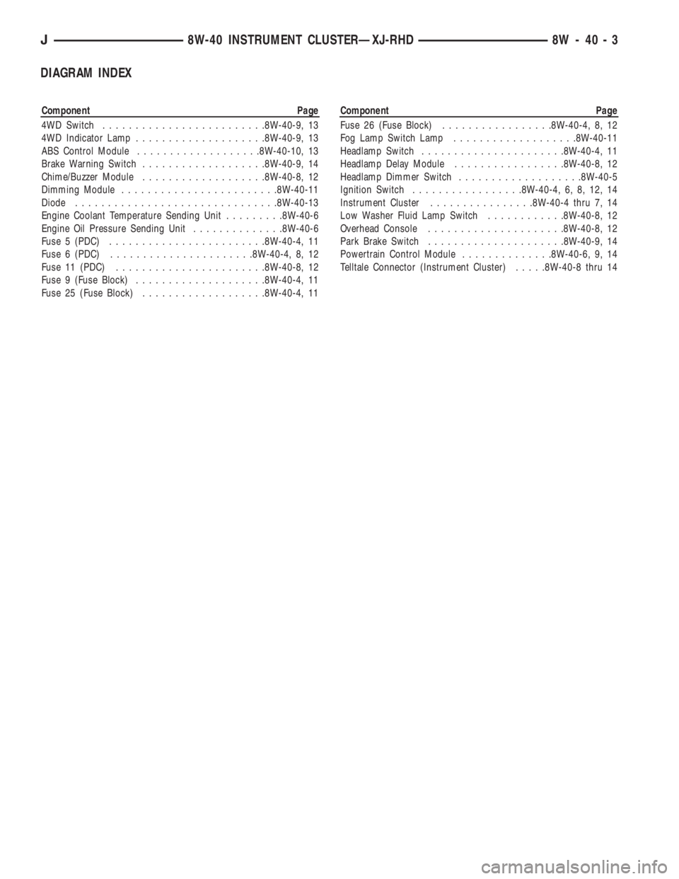
DIAGRAM INDEX
Component Page
4WD Switch.........................8W-40-9, 13
4WD Indicator Lamp....................8W-40-9, 13
ABS Control Module...................8W-40-10, 13
Brake Warning Switch...................8W-40-9, 14
Chime/Buzzer Module...................8W-40-8, 12
Dimming Module........................8W-40-11
Diode...............................8W-40-13
Engine Coolant Temperature Sending Unit.........8W-40-6
Engine Oil Pressure Sending Unit..............8W-40-6
Fuse 5 (PDC)........................8W-40-4, 11
Fuse 6 (PDC)......................8W-40-4, 8, 12
Fuse 11 (PDC).......................8W-40-8, 12
Fuse 9 (Fuse Block)....................8W-40-4, 11
Fuse 25 (Fuse Block)...................8W-40-4, 11Component Page
Fuse 26 (Fuse Block).................8W-40-4, 8, 12
Fog Lamp Switch Lamp...................8W-40-11
Headlamp Switch......................8W-40-4, 11
Headlamp Delay Module.................8W-40-8, 12
Headlamp Dimmer Switch...................8W-40-5
Ignition Switch.................8W-40-4, 6, 8, 12, 14
Instrument Cluster................8W-40-4 thru 7, 14
Low Washer Fluid Lamp Switch............8W-40-8, 12
Overhead Console.....................8W-40-8, 12
Park Brake Switch.....................8W-40-9, 14
Powertrain Control Module..............8W-40-6, 9, 14
Telltale Connector (Instrument Cluster).....8W-40-8 thru 14
J8W-40 INSTRUMENT CLUSTERÐXJ-RHD 8W - 40 - 3
Page 1068 of 2158
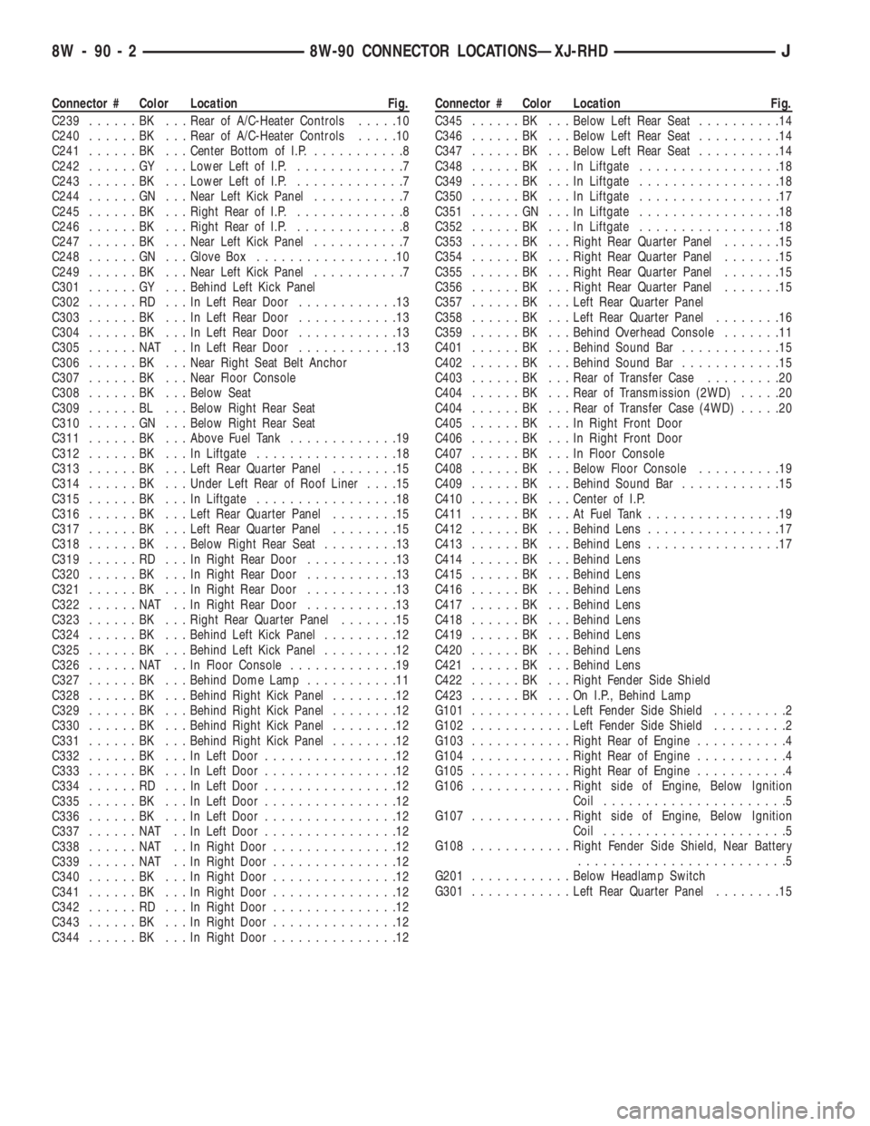
Connector # Color Location Fig.
C239......BK ...Rear of A/C-Heater Controls.....10
C240......BK ...Rear of A/C-Heater Controls.....10
C241......BK ...Center Bottom of I.P............8
C242......GY ...Lower Left of I.P..............7
C243......BK ...Lower Left of I.P..............7
C244......GN ...Near Left Kick Panel...........7
C245......BK ...Right Rear of I.P..............8
C246......BK ...Right Rear of I.P..............8
C247......BK ...Near Left Kick Panel...........7
C248......GN ...Glove Box.................10
C249......BK ...Near Left Kick Panel...........7
C301......GY ...Behind Left Kick Panel
C302......RD ...InLeft Rear Door............13
C303......BK ...InLeft Rear Door............13
C304......BK ...InLeft Rear Door............13
C305......NAT ..InLeft Rear Door............13
C306......BK ...Near Right Seat Belt Anchor
C307......BK ...Near Floor Console
C308......BK ...Below Seat
C309......BL ...Below Right Rear Seat
C310......GN ...Below Right Rear Seat
C311......BK ...Above Fuel Tank.............19
C312......BK ...InLiftgate.................18
C313......BK ...Left Rear Quarter Panel........15
C314......BK ...Under Left Rear of Roof Liner....15
C315......BK ...InLiftgate.................18
C316......BK ...Left Rear Quarter Panel........15
C317......BK ...Left Rear Quarter Panel........15
C318......BK ...Below Right Rear Seat.........13
C319......RD ...InRight Rear Door...........13
C320......BK ...InRight Rear Door...........13
C321......BK ...InRight Rear Door...........13
C322......NAT ..InRight Rear Door...........13
C323......BK ...Right Rear Quarter Panel.......15
C324......BK ...Behind Left Kick Panel.........12
C325......BK ...Behind Left Kick Panel.........12
C326......NAT ..InFloor Console.............19
C327......BK ...Behind Dome Lamp...........11
C328......BK ...Behind Right Kick Panel........12
C329......BK ...Behind Right Kick Panel........12
C330......BK ...Behind Right Kick Panel........12
C331......BK ...Behind Right Kick Panel........12
C332......BK ...InLeft Door................12
C333......BK ...InLeft Door................12
C334......RD ...InLeft Door................12
C335......BK ...InLeft Door................12
C336......BK ...InLeft Door................12
C337......NAT ..InLeft Door................12
C338......NAT ..InRight Door...............12
C339......NAT ..InRight Door...............12
C340......BK ...InRight Door...............12
C341......BK ...InRight Door...............12
C342......RD ...InRight Door...............12
C343......BK ...InRight Door...............12
C344......BK ...InRight Door...............12Connector # Color Location Fig.
C345......BK ...Below Left Rear Seat..........14
C346......BK ...Below Left Rear Seat..........14
C347......BK ...Below Left Rear Seat..........14
C348......BK ...InLiftgate.................18
C349......BK ...InLiftgate.................18
C350......BK ...InLiftgate.................17
C351......GN ...InLiftgate.................18
C352......BK ...InLiftgate.................18
C353......BK ...Right Rear Quarter Panel.......15
C354......BK ...Right Rear Quarter Panel.......15
C355......BK ...Right Rear Quarter Panel.......15
C356......BK ...Right Rear Quarter Panel.......15
C357......BK ...Left Rear Quarter Panel
C358......BK ...Left Rear Quarter Panel........16
C359......BK ...Behind Overhead Console.......11
C401......BK ...Behind Sound Bar............15
C402......BK ...Behind Sound Bar............15
C403......BK ...Rear of Transfer Case.........20
C404......BK ...Rear of Transmission (2WD).....20
C404......BK ...Rear of Transfer Case (4WD).....20
C405......BK ...InRight Front Door
C406......BK ...InRight Front Door
C407......BK ...InFloor Console
C408......BK ...Below Floor Console..........19
C409......BK ...Behind Sound Bar............15
C410......BK ...Center of I.P.
C411......BK ...AtFuel Tank................19
C412......BK ...Behind Lens................17
C413......BK ...Behind Lens................17
C414......BK ...Behind Lens
C415......BK ...Behind Lens
C416......BK ...Behind Lens
C417......BK ...Behind Lens
C418......BK ...Behind Lens
C419......BK ...Behind Lens
C420......BK ...Behind Lens
C421......BK ...Behind Lens
C422......BK ...Right Fender Side Shield
C423......BK ...OnI.P.,Behind Lamp
G101............Left Fender Side Shield.........2
G102............Left Fender Side Shield.........2
G103............Right Rear of Engine...........4
G104............Right Rear of Engine...........4
G105............Right Rear of Engine...........4
G106............Right side of Engine, Below Ignition
Coil......................5
G107............Right side of Engine, Below Ignition
Coil......................5
G108............Right Fender Side Shield, Near Battery
.........................5
G201............Below Headlamp Switch
G301............Left Rear Quarter Panel........15
8W - 90 - 2 8W-90 CONNECTOR LOCATIONSÐXJ-RHDJ