Page 1751 of 2158
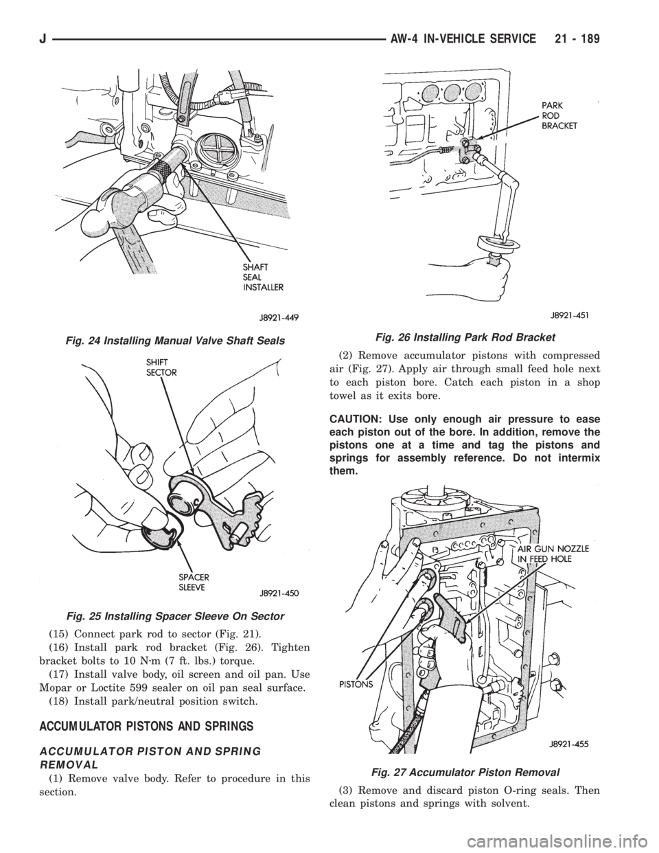
(15) Connect park rod to sector (Fig. 21).
(16) Install park rod bracket (Fig. 26). Tighten
bracket bolts to 10 Nzm (7 ft. lbs.) torque.
(17) Install valve body, oil screen and oil pan. Use
Mopar or Loctite 599 sealer on oil pan seal surface.
(18) Install park/neutral position switch.
ACCUMULATOR PISTONS AND SPRINGS
ACCUMULATOR PISTON AND SPRING
REMOVAL
(1) Remove valve body. Refer to procedure in this
section.(2) Remove accumulator pistons with compressed
air (Fig. 27). Apply air through small feed hole next
to each piston bore. Catch each piston in a shop
towel as it exits bore.
CAUTION: Use only enough air pressure to ease
each piston out of the bore. In addition, remove the
pistons one at a time and tag the pistons and
springs for assembly reference. Do not intermix
them.
(3) Remove and discard piston O-ring seals. Then
clean pistons and springs with solvent.
Fig. 24 Installing Manual Valve Shaft Seals
Fig. 25 Installing Spacer Sleeve On Sector
Fig. 26 Installing Park Rod Bracket
Fig. 27 Accumulator Piston Removal
JAW-4 IN-VEHICLE SERVICE 21 - 189
Page 1776 of 2158
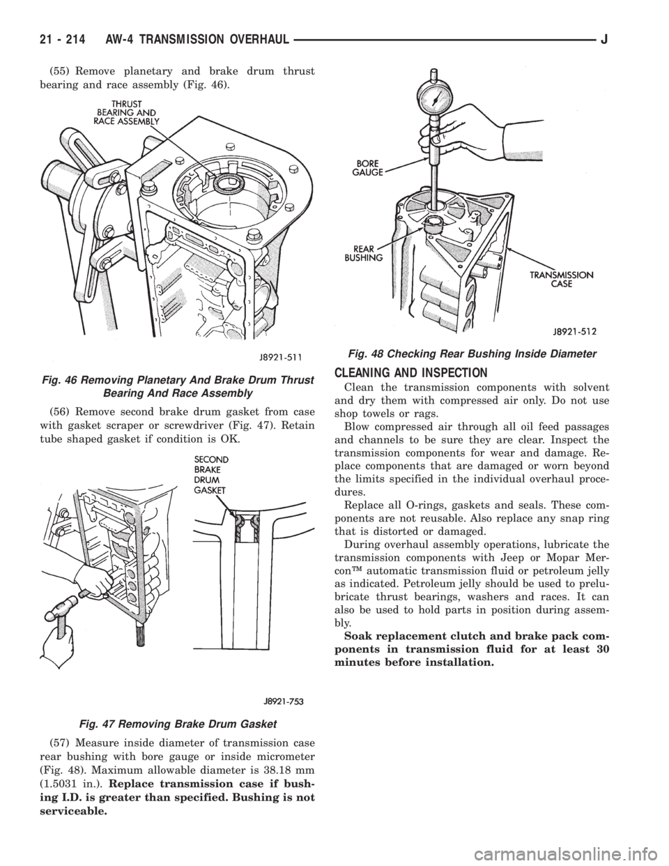
(55) Remove planetary and brake drum thrust
bearing and race assembly (Fig. 46).
(56) Remove second brake drum gasket from case
with gasket scraper or screwdriver (Fig. 47). Retain
tube shaped gasket if condition is OK.
(57) Measure inside diameter of transmission case
rear bushing with bore gauge or inside micrometer
(Fig. 48). Maximum allowable diameter is 38.18 mm
(1.5031 in.).Replace transmission case if bush-
ing I.D. is greater than specified. Bushing is not
serviceable.
CLEANING AND INSPECTION
Clean the transmission components with solvent
and dry them with compressed air only. Do not use
shop towels or rags.
Blow compressed air through all oil feed passages
and channels to be sure they are clear. Inspect the
transmission components for wear and damage. Re-
place components that are damaged or worn beyond
the limits specified in the individual overhaul proce-
dures.
Replace all O-rings, gaskets and seals. These com-
ponents are not reusable. Also replace any snap ring
that is distorted or damaged.
During overhaul assembly operations, lubricate the
transmission components with Jeep or Mopar Mer-
conŸ automatic transmission fluid or petroleum jelly
as indicated. Petroleum jelly should be used to prelu-
bricate thrust bearings, washers and races. It can
also be used to hold parts in position during assem-
bly.
Soak replacement clutch and brake pack com-
ponents in transmission fluid for at least 30
minutes before installation.Fig. 46 Removing Planetary And Brake Drum Thrust
Bearing And Race Assembly
Fig. 47 Removing Brake Drum Gasket
Fig. 48 Checking Rear Bushing Inside Diameter
21 - 214 AW-4 TRANSMISSION OVERHAULJ
Page 1797 of 2158
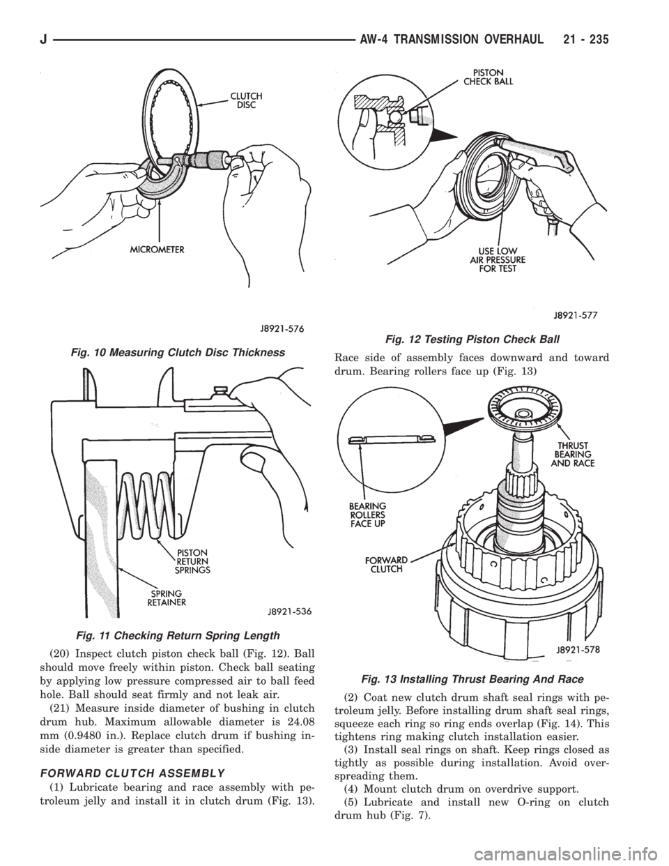
(20) Inspect clutch piston check ball (Fig. 12). Ball
should move freely within piston. Check ball seating
by applying low pressure compressed air to ball feed
hole. Ball should seat firmly and not leak air.
(21) Measure inside diameter of bushing in clutch
drum hub. Maximum allowable diameter is 24.08
mm (0.9480 in.). Replace clutch drum if bushing in-
side diameter is greater than specified.
FORWARD CLUTCH ASSEMBLY
(1) Lubricate bearing and race assembly with pe-
troleum jelly and install it in clutch drum (Fig. 13).Race side of assembly faces downward and toward
drum. Bearing rollers face up (Fig. 13)
(2) Coat new clutch drum shaft seal rings with pe-
troleum jelly. Before installing drum shaft seal rings,
squeeze each ring so ring ends overlap (Fig. 14). This
tightens ring making clutch installation easier.
(3) Install seal rings on shaft. Keep rings closed as
tightly as possible during installation. Avoid over-
spreading them.
(4) Mount clutch drum on overdrive support.
(5) Lubricate and install new O-ring on clutch
drum hub (Fig. 7).
Fig. 10 Measuring Clutch Disc Thickness
Fig. 11 Checking Return Spring Length
Fig. 12 Testing Piston Check Ball
Fig. 13 Installing Thrust Bearing And Race
JAW-4 TRANSMISSION OVERHAUL 21 - 235
Page 1816 of 2158
use shop towels or rags. Lint or foreign material from
towels or rags can interfere with valve operation.
(13) Inspect condition of lower body components.
Replace lower body if any bores are scored or cor-
roded. Replace valves, plugs or sleeves that are
scored or worn. Replace oil strainers if cut, torn or
damaged in any way.
(14) Inspect valve body springs. Replace any spring
having rusted, distorted, or collapsed coils. Measure
length of each valve body spring. Replace any spring
if free length is less than length specified in following
chart (Fig. 11).
LOWER BODY ASSEMBLY
(1) Lubricate lower body components with auto-
matic transmission fluid.
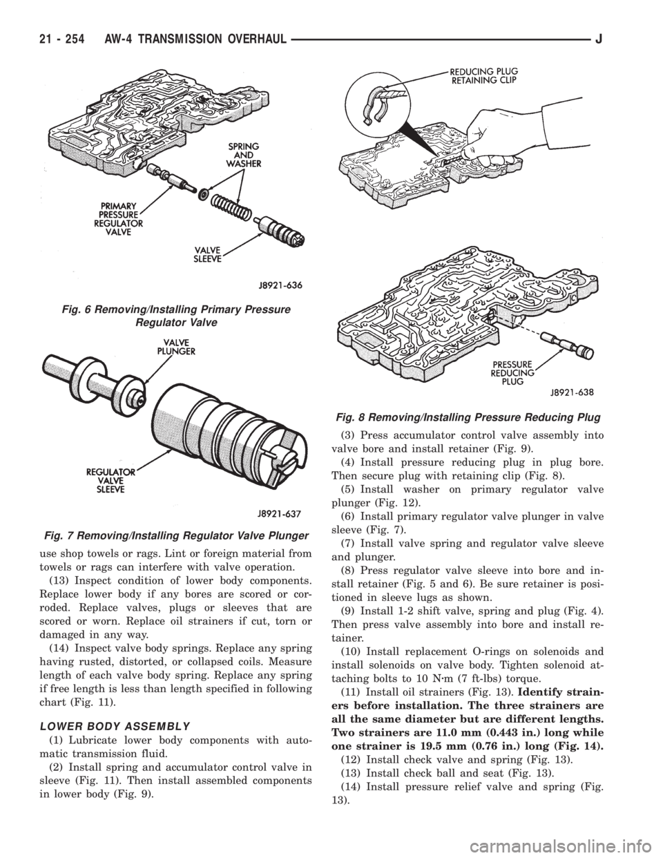
(2) Install spring and accumulator control valve in
sleeve (Fig. 11). Then install assembled components
in lower body (Fig. 9).(3) Press accumulator control valve assembly into
valve bore and install retainer (Fig. 9).
(4) Install pressure reducing plug in plug bore.
Then secure plug with retaining clip (Fig. 8).
(5) Install washer on primary regulator valve
plunger (Fig. 12).
(6) Install primary regulator valve plunger in valve
sleeve (Fig. 7).
(7) Install valve spring and regulator valve sleeve
and plunger.
(8) Press regulator valve sleeve into bore and in-
stall retainer (Fig. 5 and 6). Be sure retainer is posi-
tioned in sleeve lugs as shown.
(9) Install 1-2 shift valve, spring and plug (Fig. 4).
Then press valve assembly into bore and install re-
tainer.
(10) Install replacement O-rings on solenoids and
install solenoids on valve body. Tighten solenoid at-
taching bolts to 10 Nzm (7 ft-lbs) torque.
(11) Install oil strainers (Fig. 13).Identify strain-
ers before installation. The three strainers are
all the same diameter but are different lengths.
Two strainers are 11.0 mm (0.443 in.) long while
one strainer is 19.5 mm (0.76 in.) long (Fig. 14).
(12) Install check valve and spring (Fig. 13).
(13) Install check ball and seat (Fig. 13).
(14) Install pressure relief valve and spring (Fig.
13).
Fig. 6 Removing/Installing Primary Pressure
Regulator Valve
Fig. 7 Removing/Installing Regulator Valve Plunger
Fig. 8 Removing/Installing Pressure Reducing Plug
21 - 254 AW-4 TRANSMISSION OVERHAULJ
Page 1820 of 2158
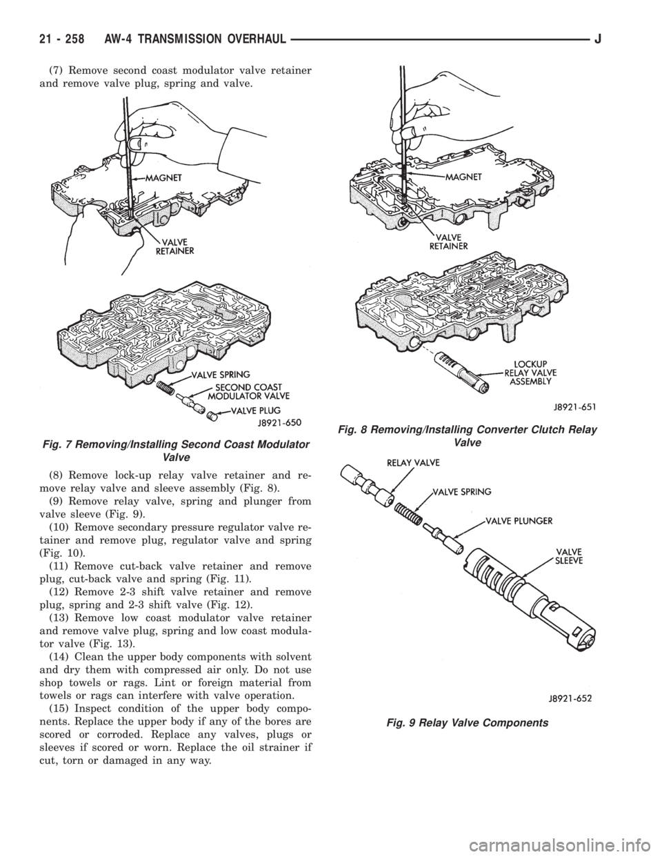
(7) Remove second coast modulator valve retainer
and remove valve plug, spring and valve.
(8) Remove lock-up relay valve retainer and re-
move relay valve and sleeve assembly (Fig. 8).
(9) Remove relay valve, spring and plunger from
valve sleeve (Fig. 9).
(10) Remove secondary pressure regulator valve re-
tainer and remove plug, regulator valve and spring
(Fig. 10).
(11) Remove cut-back valve retainer and remove
plug, cut-back valve and spring (Fig. 11).
(12) Remove 2-3 shift valve retainer and remove
plug, spring and 2-3 shift valve (Fig. 12).
(13) Remove low coast modulator valve retainer
and remove valve plug, spring and low coast modula-
tor valve (Fig. 13).
(14) Clean the upper body components with solvent
and dry them with compressed air only. Do not use
shop towels or rags. Lint or foreign material from
towels or rags can interfere with valve operation.
(15) Inspect condition of the upper body compo-
nents. Replace the upper body if any of the bores are
scored or corroded. Replace any valves, plugs or
sleeves if scored or worn. Replace the oil strainer if
cut, torn or damaged in any way.
Fig. 7 Removing/Installing Second Coast Modulator
Valve
Fig. 8 Removing/Installing Converter Clutch Relay
Valve
Fig. 9 Relay Valve Components
21 - 258 AW-4 TRANSMISSION OVERHAULJ
Page 1829 of 2158
(11) Install second brake piston sleeve (Fig. 8).
Sleeve lip faces up and toward case front as shown.
(12) Install second brake drum gasket with In-
staller Tool 7544 (Fig. 9). Gasket depth is 43.7 mm
(1.720 in.).(13) Install park lock pawl, spring and pin (Fig.
10).
(14) Connect park lock rod to manual valve shift
sector (Fig. 11).
Fig. 8 Installing Second Brake piston Sleeve
Fig. 9 Installing Second Brake Drum Gasket
Fig. 10 Installing Park Lock Pin, Spring And Pawl
Fig. 11 Installing Park Lock Rod
JAW-4 TRANSMISSION OVERHAUL 21 - 267
Page 1830 of 2158
(15) Position park lock rod bracket on case and
tighten bracket attaching bolts to 10 Nzm (7 ft. lbs.)
torque (Fig. 12).
(16) Verify park lock operation. Move shift sector
to Park position. Park pawl should be firmly engaged
(locked) in planetary ring gear (Fig. 13).(17) Install No. 1 one-way clutch (Fig. 14). Short
flanged side of clutch faces up and toward case front.
(18) Install second brake pack (Fig. 15). Install
disc then plate. Continue installation sequence until
correct number of discs-plates are installed. Use five
discs and five plates.
(19) Install second brake pack retainer with
rounded edge of retainer facing disc.
(20) Install second brake pack snap ring.
Fig. 12 Installing Park Rod Bracket
Fig. 13 Checking Park Pawl Engagement
Fig. 14 Installing No. 1 One-Way Clutch
Fig. 15 Installing Second Brake Pack
21 - 268 AW-4 TRANSMISSION OVERHAULJ
Page 1832 of 2158
(25) Install planetary snap ring on sun gear with
snap ring plier tool 7541 (Fig. 20).
(26) Install tabbed thrust race on front planetary
gear (Fig. 21). Washer tabs face down and toward
gear. Race outer diameter is 47.8 mm (1.882 in.). In-
side diameter is 34.3 mm (1.350 in.).
(27) Install second coast brake band (Fig. 22).
(28) Install pin in second coast brake band. Then
install retaining ring on pin (Fig. 23).
(29) Install thrust bearing and race in forward-di-
rect clutch (Fig. 24). Coat bearing/race with petro-
leum jelly to hold them in place.
Fig. 22 Installing Second Coast Brake Band
Fig. 23 Installing Second Coast Brake Band Retaining Pin
Fig. 20 Installing Front Planetary Snap Ring
Fig. 21 Installing Planetary Thrust Race
21 - 270 AW-4 TRANSMISSION OVERHAULJ