1995 JEEP XJ tow
[x] Cancel search: towPage 1697 of 2158
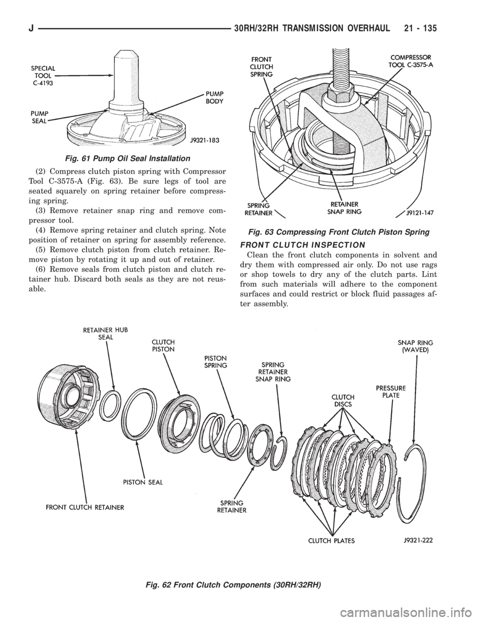
(2) Compress clutch piston spring with Compressor
Tool C-3575-A (Fig. 63). Be sure legs of tool are
seated squarely on spring retainer before compress-
ing spring.
(3) Remove retainer snap ring and remove com-
pressor tool.
(4) Remove spring retainer and clutch spring. Note
position of retainer on spring for assembly reference.
(5) Remove clutch piston from clutch retainer. Re-
move piston by rotating it up and out of retainer.
(6) Remove seals from clutch piston and clutch re-
tainer hub. Discard both seals as they are not reus-
able.
FRONT CLUTCH INSPECTION
Clean the front clutch components in solvent and
dry them with compressed air only. Do not use rags
or shop towels to dry any of the clutch parts. Lint
from such materials will adhere to the component
surfaces and could restrict or block fluid passages af-
ter assembly.
Fig. 63 Compressing Front Clutch Piston Spring
Fig. 62 Front Clutch Components (30RH/32RH)
Fig. 61 Pump Oil Seal Installation
J30RH/32RH TRANSMISSION OVERHAUL 21 - 135
Page 1700 of 2158
REAR CLUTCH OVERHAUL
REAR CLUTCH DISASSEMBLY
(1) Remove fiber thrust washer from forward side
of clutch retainer.
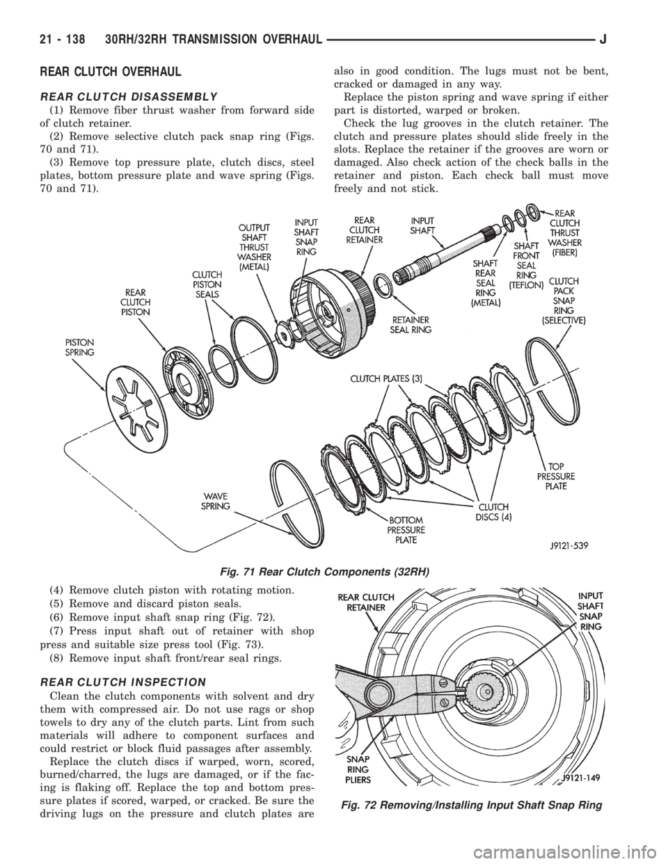
(2) Remove selective clutch pack snap ring (Figs.
70 and 71).
(3) Remove top pressure plate, clutch discs, steel
plates, bottom pressure plate and wave spring (Figs.
70 and 71).
(4) Remove clutch piston with rotating motion.
(5) Remove and discard piston seals.
(6) Remove input shaft snap ring (Fig. 72).
(7) Press input shaft out of retainer with shop
press and suitable size press tool (Fig. 73).
(8) Remove input shaft front/rear seal rings.
REAR CLUTCH INSPECTION
Clean the clutch components with solvent and dry
them with compressed air. Do not use rags or shop
towels to dry any of the clutch parts. Lint from such
materials will adhere to component surfaces and
could restrict or block fluid passages after assembly.
Replace the clutch discs if warped, worn, scored,
burned/charred, the lugs are damaged, or if the fac-
ing is flaking off. Replace the top and bottom pres-
sure plates if scored, warped, or cracked. Be sure the
driving lugs on the pressure and clutch plates arealso in good condition. The lugs must not be bent,
cracked or damaged in any way.
Replace the piston spring and wave spring if either
part is distorted, warped or broken.
Check the lug grooves in the clutch retainer. The
clutch and pressure plates should slide freely in the
slots. Replace the retainer if the grooves are worn or
damaged. Also check action of the check balls in the
retainer and piston. Each check ball must move
freely and not stick.
Fig. 71 Rear Clutch Components (32RH)
Fig. 72 Removing/Installing Input Shaft Snap Ring
21 - 138 30RH/32RH TRANSMISSION OVERHAULJ
Page 1702 of 2158
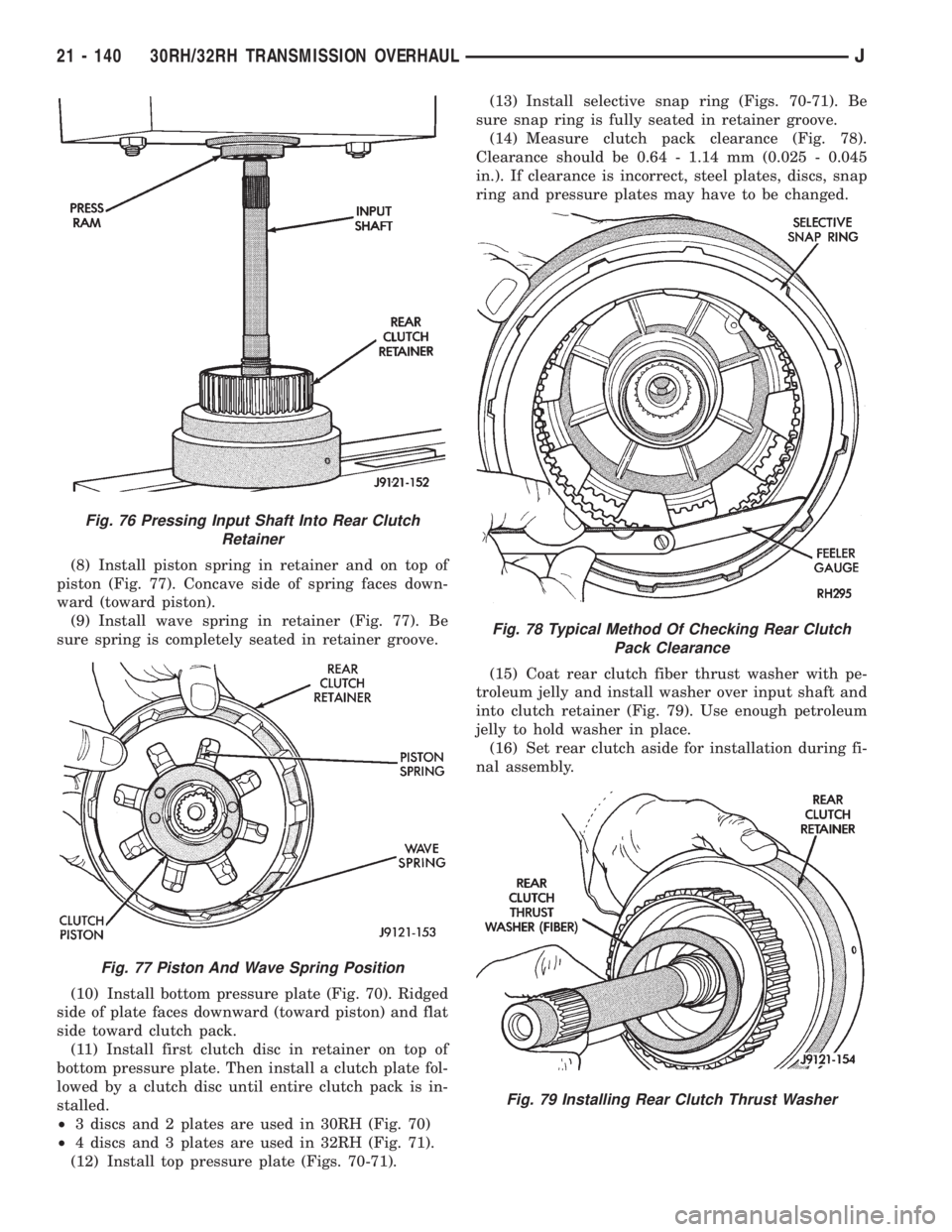
(8) Install piston spring in retainer and on top of
piston (Fig. 77). Concave side of spring faces down-
ward (toward piston).
(9) Install wave spring in retainer (Fig. 77). Be
sure spring is completely seated in retainer groove.
(10) Install bottom pressure plate (Fig. 70). Ridged
side of plate faces downward (toward piston) and flat
side toward clutch pack.
(11) Install first clutch disc in retainer on top of
bottom pressure plate. Then install a clutch plate fol-
lowed by a clutch disc until entire clutch pack is in-
stalled.
²3 discs and 2 plates are used in 30RH (Fig. 70)
²4 discs and 3 plates are used in 32RH (Fig. 71).
(12) Install top pressure plate (Figs. 70-71).(13) Install selective snap ring (Figs. 70-71). Be
sure snap ring is fully seated in retainer groove.
(14) Measure clutch pack clearance (Fig. 78).
Clearance should be 0.64 - 1.14 mm (0.025 - 0.045
in.). If clearance is incorrect, steel plates, discs, snap
ring and pressure plates may have to be changed.
(15) Coat rear clutch fiber thrust washer with pe-
troleum jelly and install washer over input shaft and
into clutch retainer (Fig. 79). Use enough petroleum
jelly to hold washer in place.
(16) Set rear clutch aside for installation during fi-
nal assembly.
Fig. 76 Pressing Input Shaft Into Rear Clutch
Retainer
Fig. 77 Piston And Wave Spring Position
Fig. 78 Typical Method Of Checking Rear Clutch
Pack Clearance
Fig. 79 Installing Rear Clutch Thrust Washer
21 - 140 30RH/32RH TRANSMISSION OVERHAULJ
Page 1709 of 2158
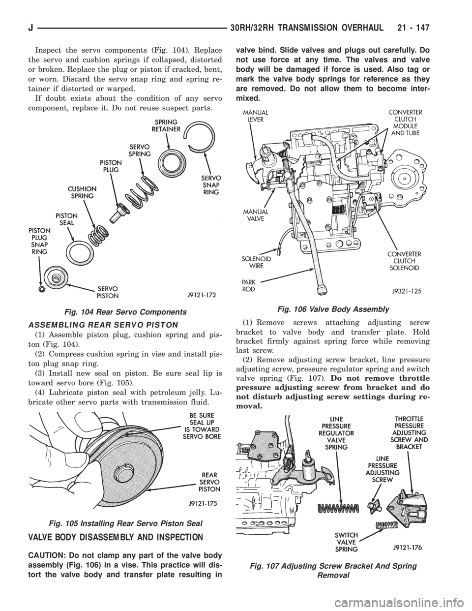
Inspect the servo components (Fig. 104). Replace
the servo and cushion springs if collapsed, distorted
or broken. Replace the plug or piston if cracked, bent,
or worn. Discard the servo snap ring and spring re-
tainer if distorted or warped.
If doubt exists about the condition of any servo
component, replace it. Do not reuse suspect parts.
ASSEMBLING REAR SERVO PISTON
(1) Assemble piston plug, cushion spring and pis-
ton (Fig. 104).
(2) Compress cushion spring in vise and install pis-
ton plug snap ring.
(3) Install new seal on piston. Be sure seal lip is
toward servo bore (Fig. 105).
(4) Lubricate piston seal with petroleum jelly. Lu-
bricate other servo parts with transmission fluid.
VALVE BODY DISASSEMBLY AND INSPECTION
CAUTION: Do not clamp any part of the valve body
assembly (Fig. 106) in a vise. This practice will dis-
tort the valve body and transfer plate resulting invalve bind. Slide valves and plugs out carefully. Do
not use force at any time. The valves and valve
body will be damaged if force is used. Also tag or
mark the valve body springs for reference as they
are removed. Do not allow them to become inter-
mixed.
(1) Remove screws attaching adjusting screw
bracket to valve body and transfer plate. Hold
bracket firmly against spring force while removing
last screw.
(2) Remove adjusting screw bracket, line pressure
adjusting screw, pressure regulator spring and switch
valve spring (Fig. 107).Do not remove throttle
pressure adjusting screw from bracket and do
not disturb adjusting screw settings during re-
moval.
Fig. 104 Rear Servo Components
Fig. 105 Installing Rear Servo Piston Seal
Fig. 106 Valve Body Assembly
Fig. 107 Adjusting Screw Bracket And Spring
Removal
J30RH/32RH TRANSMISSION OVERHAUL 21 - 147
Page 1712 of 2158
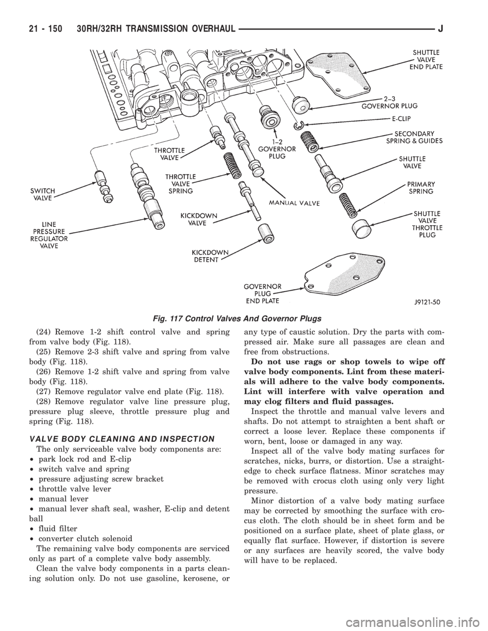
(24) Remove 1-2 shift control valve and spring
from valve body (Fig. 118).
(25) Remove 2-3 shift valve and spring from valve
body (Fig. 118).
(26) Remove 1-2 shift valve and spring from valve
body (Fig. 118).
(27) Remove regulator valve end plate (Fig. 118).
(28) Remove regulator valve line pressure plug,
pressure plug sleeve, throttle pressure plug and
spring (Fig. 118).
VALVE BODY CLEANING AND INSPECTION
The only serviceable valve body components are:
²park lock rod and E-clip
²switch valve and spring
²pressure adjusting screw bracket
²throttle valve lever
²manual lever
²manual lever shaft seal, washer, E-clip and detent
ball
²fluid filter
²converter clutch solenoid
The remaining valve body components are serviced
only as part of a complete valve body assembly.
Clean the valve body components in a parts clean-
ing solution only. Do not use gasoline, kerosene, orany type of caustic solution. Dry the parts with com-
pressed air. Make sure all passages are clean and
free from obstructions.
Do not use rags or shop towels to wipe off
valve body components. Lint from these materi-
als will adhere to the valve body components.
Lint will interfere with valve operation and
may clog filters and fluid passages.
Inspect the throttle and manual valve levers and
shafts. Do not attempt to straighten a bent shaft or
correct a loose lever. Replace these components if
worn, bent, loose or damaged in any way.
Inspect all of the valve body mating surfaces for
scratches, nicks, burrs, or distortion. Use a straight-
edge to check surface flatness. Minor scratches may
be removed with crocus cloth using only very light
pressure.
Minor distortion of a valve body mating surface
may be corrected by smoothing the surface with cro-
cus cloth. The cloth should be in sheet form and be
positioned on a surface plate, sheet of plate glass, or
equally flat surface. However, if distortion is severe
or any surfaces are heavily scored, the valve body
will have to be replaced.
Fig. 117 Control Valves And Governor Plugs
21 - 150 30RH/32RH TRANSMISSION OVERHAULJ
Page 1717 of 2158
justment must be performed properly and in the cor-
rect sequence. The correct sequence is line pressure
adjustment first and throttle pressure adjustment
last.
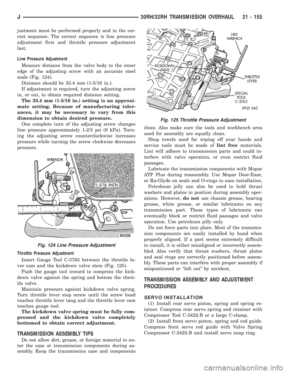
Line Pressure Adjustment
Measure distance from the valve body to the inner
edge of the adjusting screw with an accurate steel
scale (Fig. 124).
Distance should be 33.4 mm (1-5/16 in.).
If adjustment is required, turn the adjusting screw
in, or out, to obtain required distance setting.
The 33.4 mm (1-5/16 in.) setting is an approxi-
mate setting. Because of manufacturing toler-
ances, it may be necessary to vary from this
dimension to obtain desired pressure.
One complete turn of the adjusting screw changes
line pressure approximately 1-2/3 psi (9 kPa). Turn-
ing the adjusting screw counterclockwise increases
pressure while turning the screw clockwise decreases
pressure.
Throttle Pressure Adjustment
Insert Gauge Tool C-3763 between the throttle le-
ver cam and the kickdown valve stem (Fig. 125).
Push the gauge tool inward to compress the kick-
down valve against the spring and bottom the throt-
tle valve.
Maintain pressure against kickdown valve spring.
Turn throttle lever stop screw until the screw head
touches throttle lever tang and the throttle lever cam
touches gauge tool.
The kickdown valve spring must be fully com-
pressed and the kickdown valve completely
bottomed to obtain correct adjustment.
TRANSMISSION ASSEMBLY TIPS
Do not allow dirt, grease, or foreign material to en-
ter the case or transmission components during as-
sembly. Keep the transmission case and componentsclean. Also make sure the tools and workbench area
used for assembly are equally clean.
Shop towels used for wiping off your hands and
service tools must be made oflint freematerials.
Lint will adhere to transmission parts and could in-
terfere with valve operation, or even restrict fluid
passages.
Lubricate the transmission components with Mopar
ATF Plus during reassembly. Use Mopar Door-Ease,
or Ru-Glyde on seals and O-rings to ease installation.
Petroleum jelly can also be used to hold thrust
washers and plates in position during assembly oper-
ations. However,do notuse chassis grease, bearing
grease, white grease, or similar lubricants on any
transmission part. These types of lubricants can
eventually block or restrict fluid passages and valve
operation. Use petroleum jelly only.
Do not force parts into place. Most of the transmis-
sion components are easily installed by hand when
properly aligned. If a part seems extremely difficult
to install, it is either misaligned or incorrectly assem-
bled. Also verify that thrust washers, thrust plates
and seal rings are correctly positioned before assem-
bly. These parts can interfere with proper assembly if
mispositioned or ``left out'' by accident.
TRANSMISSION ASSEMBLY AND ADJUSTMENT
PROCEDURES
SERVO INSTALLATION
(1) Install rear servo piston, spring and spring re-
tainer. Compress rear servo spring and retainer with
Compressor Tool C-3422-B or a large C-clamp.
(2) Install front servo piston, spring and rod guide.
Compress front servo rod guide with Valve Spring
Compressor C-3422-B and install servo snap ring.
Fig. 124 Line Pressure Adjustment
Fig. 125 Throttle Pressure Adjustment
J30RH/32RH TRANSMISSION OVERHAUL 21 - 155
Page 1723 of 2158
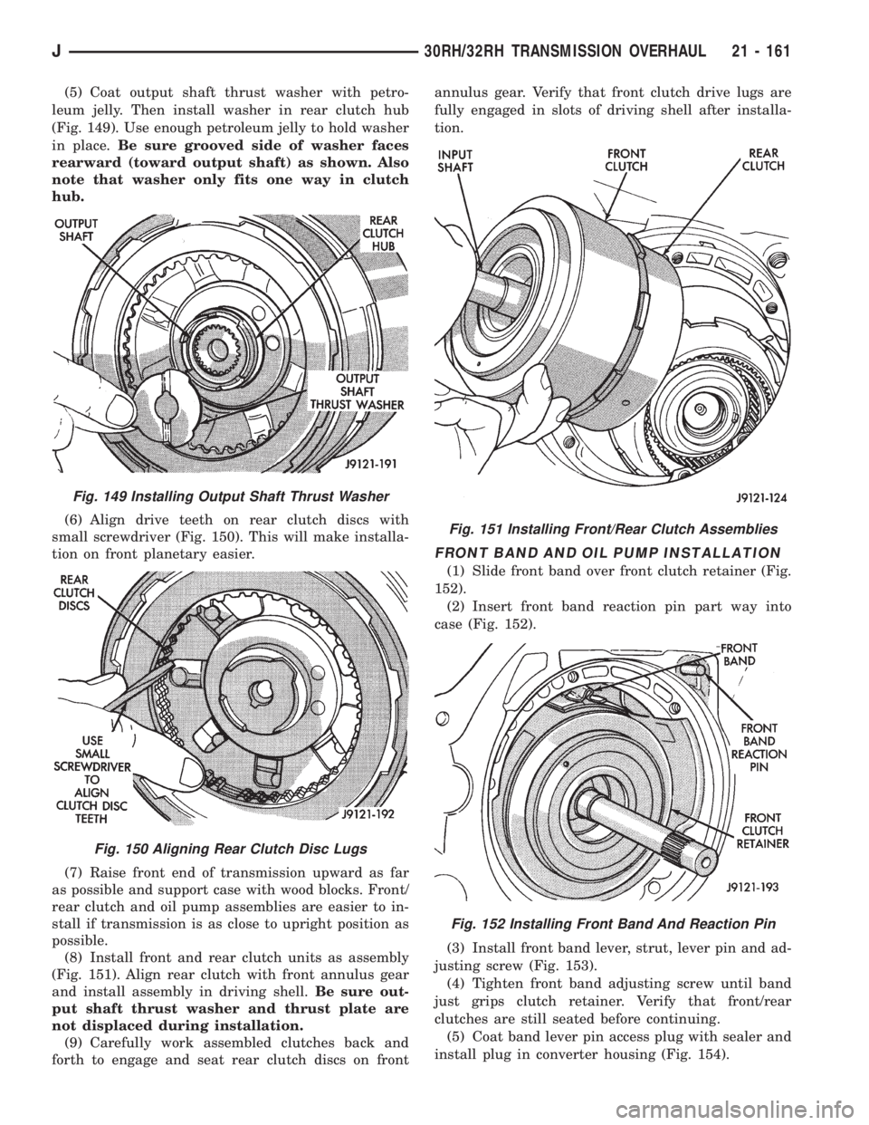
(5) Coat output shaft thrust washer with petro-
leum jelly. Then install washer in rear clutch hub
(Fig. 149). Use enough petroleum jelly to hold washer
in place.Be sure grooved side of washer faces
rearward (toward output shaft) as shown. Also
note that washer only fits one way in clutch
hub.
(6) Align drive teeth on rear clutch discs with
small screwdriver (Fig. 150). This will make installa-
tion on front planetary easier.
(7) Raise front end of transmission upward as far
as possible and support case with wood blocks. Front/
rear clutch and oil pump assemblies are easier to in-
stall if transmission is as close to upright position as
possible.
(8) Install front and rear clutch units as assembly
(Fig. 151). Align rear clutch with front annulus gear
and install assembly in driving shell.Be sure out-
put shaft thrust washer and thrust plate are
not displaced during installation.
(9) Carefully work assembled clutches back and
forth to engage and seat rear clutch discs on frontannulus gear. Verify that front clutch drive lugs are
fully engaged in slots of driving shell after installa-
tion.
FRONT BAND AND OIL PUMP INSTALLATION
(1) Slide front band over front clutch retainer (Fig.
152).
(2) Insert front band reaction pin part way into
case (Fig. 152).
(3) Install front band lever, strut, lever pin and ad-
justing screw (Fig. 153).
(4) Tighten front band adjusting screw until band
just grips clutch retainer. Verify that front/rear
clutches are still seated before continuing.
(5) Coat band lever pin access plug with sealer and
install plug in converter housing (Fig. 154).
Fig. 149 Installing Output Shaft Thrust Washer
Fig. 150 Aligning Rear Clutch Disc Lugs
Fig. 151 Installing Front/Rear Clutch Assemblies
Fig. 152 Installing Front Band And Reaction Pin
J30RH/32RH TRANSMISSION OVERHAUL 21 - 161
Page 1749 of 2158
TRANSMISSION VALVE BODY INSTALLATION
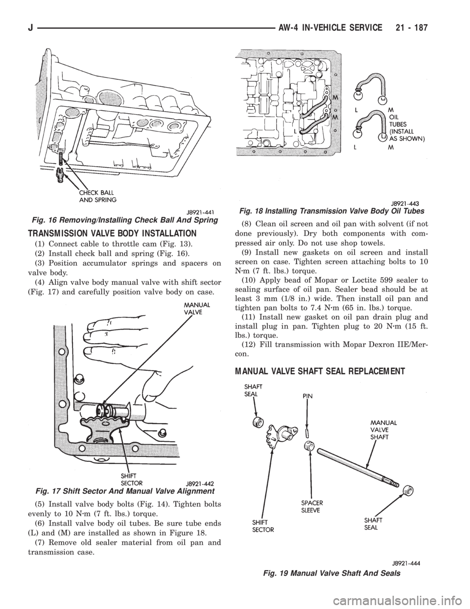
(1) Connect cable to throttle cam (Fig. 13).
(2) Install check ball and spring (Fig. 16).
(3) Position accumulator springs and spacers on
valve body.
(4) Align valve body manual valve with shift sector
(Fig. 17) and carefully position valve body on case.
(5) Install valve body bolts (Fig. 14). Tighten bolts
evenly to 10 Nzm (7 ft. lbs.) torque.
(6) Install valve body oil tubes. Be sure tube ends
(L) and (M) are installed as shown in Figure 18.
(7) Remove old sealer material from oil pan and
transmission case.(8) Clean oil screen and oil pan with solvent (if not
done previously). Dry both components with com-
pressed air only. Do not use shop towels.
(9) Install new gaskets on oil screen and install
screen on case. Tighten screen attaching bolts to 10
Nzm (7 ft. lbs.) torque.
(10) Apply bead of Mopar or Loctite 599 sealer to
sealing surface of oil pan. Sealer bead should be at
least 3 mm (1/8 in.) wide. Then install oil pan and
tighten pan bolts to 7.4 Nzm (65 in. lbs.) torque.
(11) Install new gasket on oil pan drain plug and
install plug in pan. Tighten plug to 20 Nzm (15 ft.
lbs.) torque.
(12) Fill transmission with Mopar Dexron IIE/Mer-
con.
MANUAL VALVE SHAFT SEAL REPLACEMENT
Fig. 16 Removing/Installing Check Ball And Spring
Fig. 17 Shift Sector And Manual Valve Alignment
Fig. 18 Installing Transmission Valve Body Oil Tubes
Fig. 19 Manual Valve Shaft And Seals
JAW-4 IN-VEHICLE SERVICE 21 - 187