1995 JEEP XJ brake
[x] Cancel search: brakePage 417 of 2158

VEHICLE SPEED CONTROL SYSTEM
CONTENTS
page page
DIAGNOSIS............................. 2
GENERAL INFORMATION.................. 1SERVICE PROCEDURES................... 9
GENERAL INFORMATION
The vehicle speed control system (Fig. 1) is an
available option on all XJ (Cherokee) models. The
system is electronically controlled and vacuum oper-
ated. Following are general descriptions of the major
components in the vehicle speed control system. Re-
fer to Group 8W - Wiring Diagrams for complete cir-
cuit descriptions and diagrams.
SPEED CONTROL SERVO
The speed control servo is mounted to a bracket on
the right side inner fender shield in the engine com-
partment. The servo unit consists of a solenoid valve
body, a vacuum servo and the mounting bracket. The
PCM controls the solenoid valve body. The solenoid
valve body controls the application and release of
vacuum to the diaphragm of the vacuum servo. The
servo unit cannot be repaired and is serviced only as
a complete assembly.
SPEED CONTROL SWITCH
The speed control switch module is mounted to the
center of the steering wheel below the driver's airbag
module. The PCM monitors the state of the speed
control switches. The individual switches are labeled:
OFF/ON, RESUME/ACCEL, SET/COAST. Refer to
the owner's manual for more information on speed
control switch functions and setting procedures. The
individual switches cannot be repaired. If one switch
fails, the entire switch module must be replaced.
STOP LAMP SWITCH
Vehicles with the speed control option use a dual
function stop lamp switch. The switch is mounted in
the same location as the conventional stop lamp
switch, on the brake pedal mounting bracket under
the instrument panel. The PCM monitors the state of
the dual function stop lamp switch. Refer to Group 5
- Brakes for more information on stop lamp switch
service and adjustment procedures.
SERVO CABLE
The speed control servo cable is connected betweenthe speed control vacuum servo diaphragm and the
throttle control linkage. This cable causes the throt-
tle control linkage to open or close the throttle valve
in response to movement of the vacuum servo dia-
phragm.
POWERTRAIN CONTROL MODULE
The speed control electronic control circuitry is in-
tegrated into the Powertrain Control Module (PCM).
The PCM is located in the engine compartment on
the left side inner fender shield. The PCM speed con-
trol functions are monitored by the On-Board Diag-
nostics (OBD). All OBD-sensed systems are
monitored by the PCM. Each monitored circuit is as-
signed a Diagnostic Trouble Code (DTC). The PCM
will store a DTC in electronic memory for any failure
it detects. See Using On-Board Diagnostic System in
this group for more information. The PCM cannot be
repaired and must be replaced if faulty.
VACUUM RESERVOIR
The vacuum reservoir is mounted behind the left
end of the front bumper bar. The reservoir contains a
one-way check valve to trap engine vacuum in the
reservoir. When engine vacuum drops, as in climbing
a grade while driving, the reservoir supplies the vac-
uum needed to maintain proper speed control opera-
tion. The vacuum reservoir cannot be repaired and
must be replaced if faulty.
VEHICLE SPEED SENSOR
The Vehicle Speed Sensor (VSS) is a pulse genera-
tor mounted to an adapter near the transmission
(two-wheel drive) or transfer case (four-wheel drive)
output shaft. The sensor is driven through the
adapter by a speedometer pinion gear. The VSS pulse
signal to the speedometer/odometer is monitored by
the PCM speed control circuitry to determine vehicle
speed and to maintain speed control set speed. Refer
to the appropriate Powertrain Diagnostic Procedures
manual for testing of this component. Refer to Group
14 - Fuel System for service of this component.
JVEHICLE SPEED CONTROL SYSTEM 8H - 1
Page 422 of 2158
SPEED CONTROL SWITCH
WARNING: ON VEHICLES EQUIPPED WITH AN AIR-
BAG, REFER TO GROUP 8M - RESTRAINT SYS-
TEMS BEFORE ATTEMPTING STEERING WHEEL
COMPONENT DIAGNOSIS OR SERVICE. FAILURE
TO TAKE PROPER PRECAUTIONS COULD RESULT
IN ACCIDENTAL AIRBAG DEPLOYMENT AND POS-
SIBLE PERSONAL INJURY.
(1) Disconnect battery negative cable. Remove
speed control switch from steering wheel.
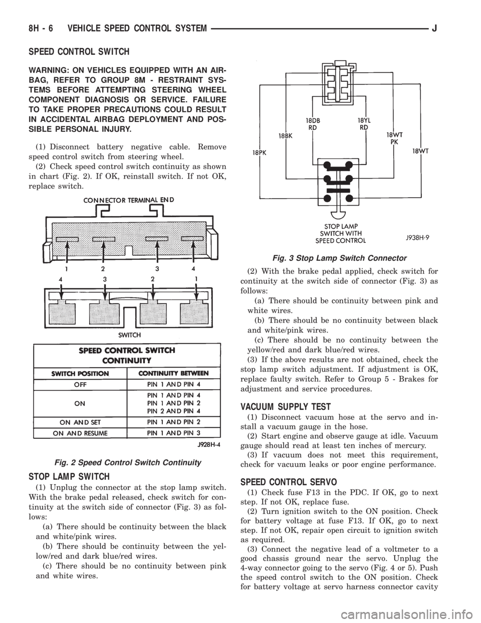
(2) Check speed control switch continuity as shown
in chart (Fig. 2). If OK, reinstall switch. If not OK,
replace switch.
STOP LAMP SWITCH
(1) Unplug the connector at the stop lamp switch.
With the brake pedal released, check switch for con-
tinuity at the switch side of connector (Fig. 3) as fol-
lows:
(a) There should be continuity between the black
and white/pink wires.
(b) There should be continuity between the yel-
low/red and dark blue/red wires.
(c) There should be no continuity between pink
and white wires.(2) With the brake pedal applied, check switch for
continuity at the switch side of connector (Fig. 3) as
follows:
(a) There should be continuity between pink and
white wires.
(b) There should be no continuity between black
and white/pink wires.
(c) There should be no continuity between the
yellow/red and dark blue/red wires.
(3) If the above results are not obtained, check the
stop lamp switch adjustment. If adjustment is OK,
replace faulty switch. Refer to Group 5 - Brakes for
adjustment and service procedures.
VACUUM SUPPLY TEST
(1) Disconnect vacuum hose at the servo and in-
stall a vacuum gauge in the hose.
(2) Start engine and observe gauge at idle. Vacuum
gauge should read at least ten inches of mercury.
(3) If vacuum does not meet this requirement,
check for vacuum leaks or poor engine performance.
SPEED CONTROL SERVO
(1) Check fuse F13 in the PDC. If OK, go to next
step. If not OK, replace fuse.
(2) Turn ignition switch to the ON position. Check
for battery voltage at fuse F13. If OK, go to next
step. If not OK, repair open circuit to ignition switch
as required.
(3) Connect the negative lead of a voltmeter to a
good chassis ground near the servo. Unplug the
4-way connector going to the servo (Fig. 4 or 5). Push
the speed control switch to the ON position. Check
for battery voltage at servo harness connector cavity
Fig. 2 Speed Control Switch Continuity
Fig. 3 Stop Lamp Switch Connector
8H - 6 VEHICLE SPEED CONTROL SYSTEMJ
Page 424 of 2158
read zero volts. With the switch in the ON position,
the voltmeter should read battery voltage. Pressing
the SET/COAST button should cause the voltmeter to
change from battery voltage to zero volts for as long
as the switch is held. If not, perform the Speed Con-
trol Switch Test. If the switch is not at fault, then
check the main harness and repair as necessary.
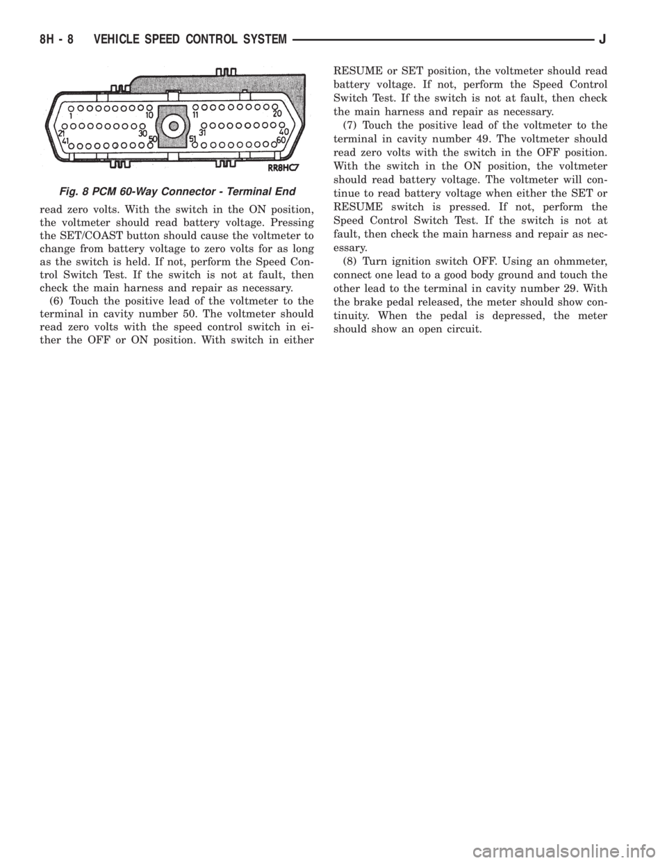
(6) Touch the positive lead of the voltmeter to the
terminal in cavity number 50. The voltmeter should
read zero volts with the speed control switch in ei-
ther the OFF or ON position. With switch in eitherRESUME or SET position, the voltmeter should read
battery voltage. If not, perform the Speed Control
Switch Test. If the switch is not at fault, then check
the main harness and repair as necessary.
(7) Touch the positive lead of the voltmeter to the
terminal in cavity number 49. The voltmeter should
read zero volts with the switch in the OFF position.
With the switch in the ON position, the voltmeter
should read battery voltage. The voltmeter will con-
tinue to read battery voltage when either the SET or
RESUME switch is pressed. If not, perform the
Speed Control Switch Test. If the switch is not at
fault, then check the main harness and repair as nec-
essary.
(8) Turn ignition switch OFF. Using an ohmmeter,
connect one lead to a good body ground and touch the
other lead to the terminal in cavity number 29. With
the brake pedal released, the meter should show con-
tinuity. When the pedal is depressed, the meter
should show an open circuit.
Fig. 8 PCM 60-Way Connector - Terminal End
8H - 8 VEHICLE SPEED CONTROL SYSTEMJ
Page 433 of 2158
(15) Remove turn/hazard switch attaching screws.
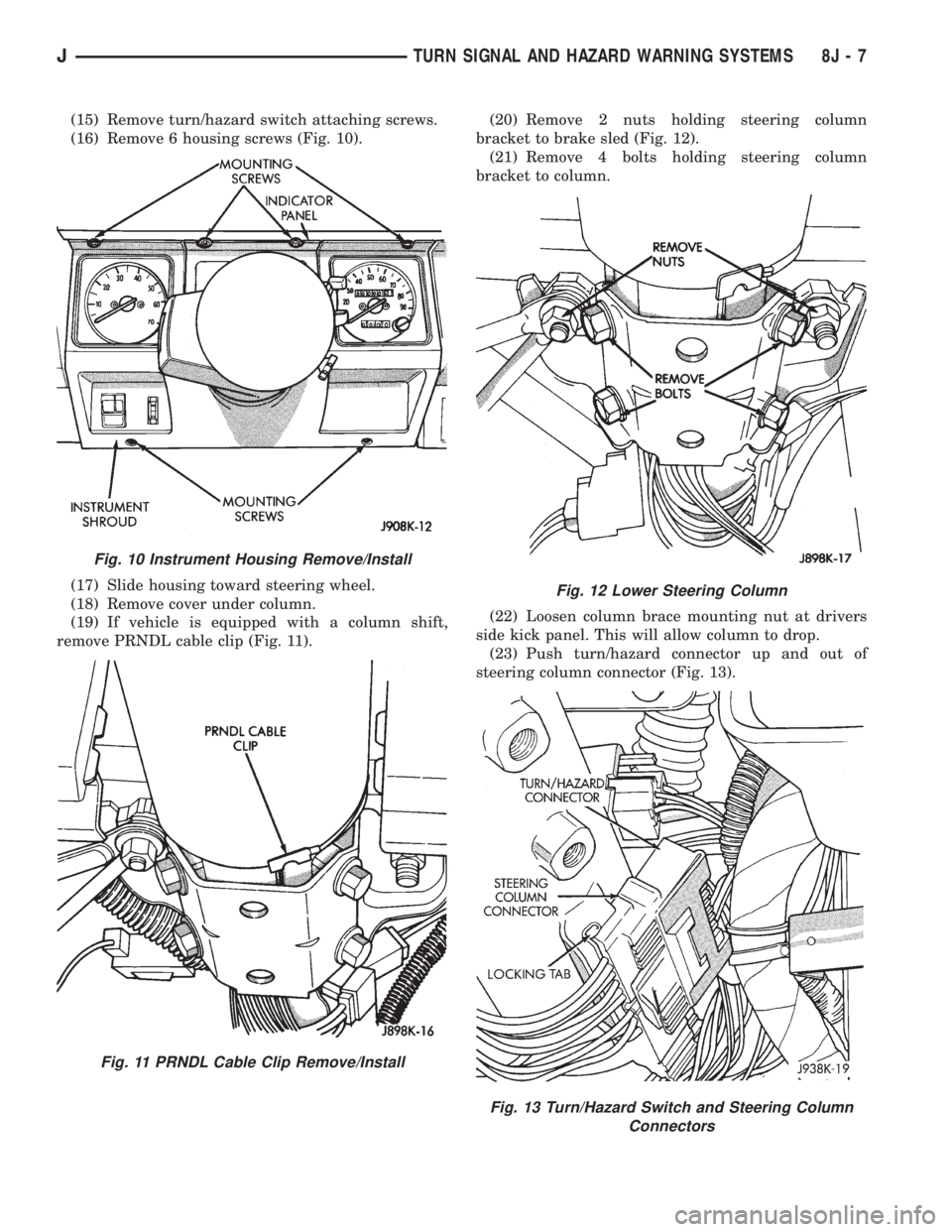
(16) Remove 6 housing screws (Fig. 10).
(17) Slide housing toward steering wheel.
(18) Remove cover under column.
(19) If vehicle is equipped with a column shift,
remove PRNDL cable clip (Fig. 11).(20) Remove 2 nuts holding steering column
bracket to brake sled (Fig. 12).
(21) Remove 4 bolts holding steering column
bracket to column.
(22) Loosen column brace mounting nut at drivers
side kick panel. This will allow column to drop.
(23) Push turn/hazard connector up and out of
steering column connector (Fig. 13).
Fig. 10 Instrument Housing Remove/Install
Fig. 11 PRNDL Cable Clip Remove/Install
Fig. 12 Lower Steering Column
Fig. 13 Turn/Hazard Switch and Steering Column
Connectors
JTURN SIGNAL AND HAZARD WARNING SYSTEMS 8J - 7
Page 456 of 2158
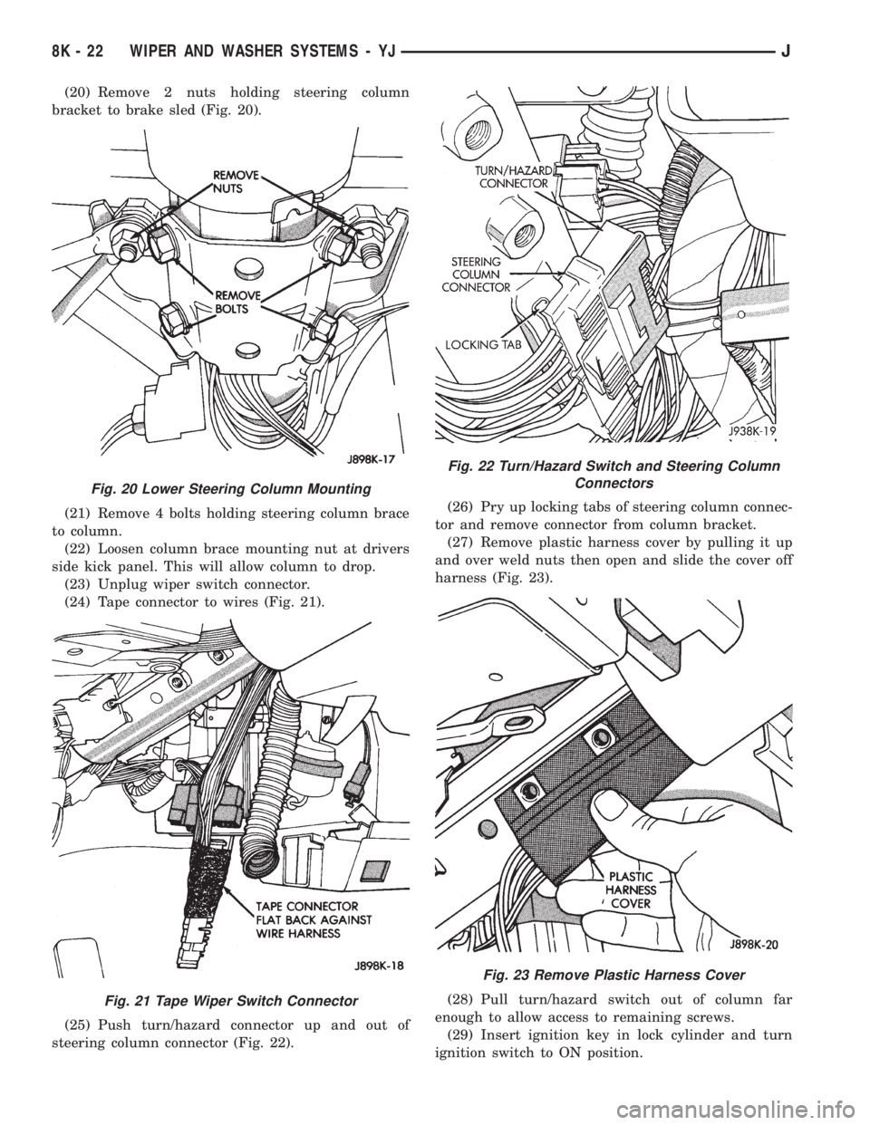
(20) Remove 2 nuts holding steering column
bracket to brake sled (Fig. 20).
(21) Remove 4 bolts holding steering column brace
to column.
(22) Loosen column brace mounting nut at drivers
side kick panel. This will allow column to drop.
(23) Unplug wiper switch connector.
(24) Tape connector to wires (Fig. 21).
(25) Push turn/hazard connector up and out of
steering column connector (Fig. 22).(26) Pry up locking tabs of steering column connec-
tor and remove connector from column bracket.
(27) Remove plastic harness cover by pulling it up
and over weld nuts then open and slide the cover off
harness (Fig. 23).
(28) Pull turn/hazard switch out of column far
enough to allow access to remaining screws.
(29) Insert ignition key in lock cylinder and turn
ignition switch to ON position.
Fig. 20 Lower Steering Column Mounting
Fig. 21 Tape Wiper Switch Connector
Fig. 22 Turn/Hazard Switch and Steering Column
Connectors
Fig. 23 Remove Plastic Harness Cover
8K - 22 WIPER AND WASHER SYSTEMS - YJJ
Page 478 of 2158
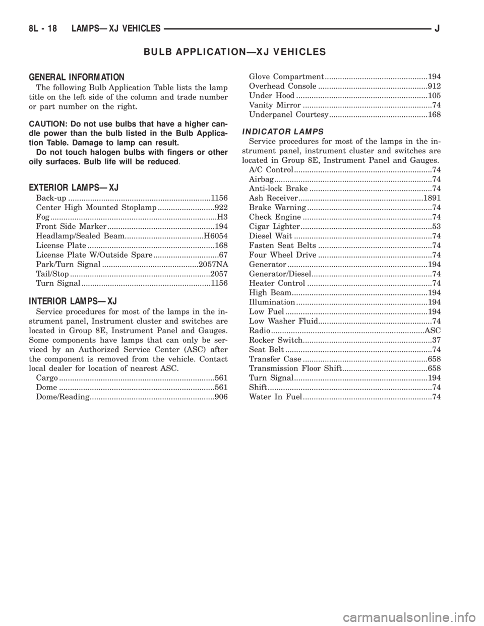
BULB APPLICATIONÐXJ VEHICLES
GENERAL INFORMATION
The following Bulb Application Table lists the lamp
title on the left side of the column and trade number
or part number on the right.
CAUTION: Do not use bulbs that have a higher can-
dle power than the bulb listed in the Bulb Applica-
tion Table. Damage to lamp can result.
Do not touch halogen bulbs with fingers or other
oily surfaces. Bulb life will be reduced.
EXTERIOR LAMPSÐXJ
Back-up .................................................................1156
Center High Mounted Stoplamp ..........................922
Fog ............................................................................H3
Front Side Marker .................................................194
Headlamp/Sealed Beam....................................H6054
License Plate ..........................................................168
License Plate W/Outside Spare ..............................67
Park/Turn Signal ............................................2057NA
Tail/Stop ................................................................2057
Turn Signal ...........................................................1156
INTERIOR LAMPSÐXJ
Service procedures for most of the lamps in the in-
strument panel, Instrument cluster and switches are
located in Group 8E, Instrument Panel and Gauges.
Some components have lamps that can only be ser-
viced by an Authorized Service Center (ASC) after
the component is removed from the vehicle. Contact
local dealer for location of nearest ASC.
Cargo .......................................................................561
Dome .......................................................................561
Dome/Reading.........................................................906Glove Compartment ...............................................194
Overhead Console ..................................................912
Under Hood ............................................................105
Vanity Mirror ...........................................................74
Underpanel Courtesy.............................................168
INDICATOR LAMPS
Service procedures for most of the lamps in the in-
strument panel, instrument cluster and switches are
located in Group 8E, Instrument Panel and Gauges.
A/C Control ...............................................................74
Airbag ........................................................................74
Anti-lock Brake ........................................................74
Ash Receiver .........................................................1891
Brake Warning .........................................................74
Check Engine ...........................................................74
Cigar Lighter ............................................................53
Diesel Wait ...............................................................74
Fasten Seat Belts ....................................................74
Four Wheel Drive ....................................................74
Generator ................................................................194
Generator/Diesel.......................................................74
Heater Control .........................................................74
High Beam..............................................................194
Illumination ............................................................194
Low Fuel .................................................................194
Low Washer Fluid....................................................74
Radio ......................................................................ASC
Rocker Switch...........................................................37
Seat Belt ...................................................................74
Transfer Case .........................................................658
Transmission Floor Shift.......................................658
Turn Signal.............................................................194
Shift ...........................................................................74
Water In Fuel ...........................................................74
8L - 18 LAMPSÐXJ VEHICLESJ
Page 492 of 2158
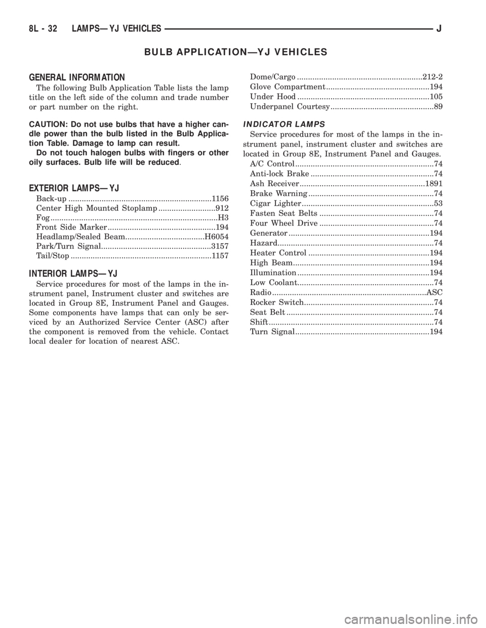
BULB APPLICATIONÐYJ VEHICLES
GENERAL INFORMATION
The following Bulb Application Table lists the lamp
title on the left side of the column and trade number
or part number on the right.
CAUTION: Do not use bulbs that have a higher can-
dle power than the bulb listed in the Bulb Applica-
tion Table. Damage to lamp can result.
Do not touch halogen bulbs with fingers or other
oily surfaces. Bulb life will be reduced.
EXTERIOR LAMPSÐYJ
Back-up .................................................................1156
Center High Mounted Stoplamp ..........................912
Fog ............................................................................H3
Front Side Marker .................................................194
Headlamp/Sealed Beam....................................H6054
Park/Turn Signal..................................................3157
Tail/Stop ................................................................1157
INTERIOR LAMPSÐYJ
Service procedures for most of the lamps in the in-
strument panel, Instrument cluster and switches are
located in Group 8E, Instrument Panel and Gauges.
Some components have lamps that can only be ser-
viced by an Authorized Service Center (ASC) after
the component is removed from the vehicle. Contact
local dealer for location of nearest ASC.Dome/Cargo .........................................................212-2
Glove Compartment ...............................................194
Under Hood ............................................................105
Underpanel Courtesy...............................................89
INDICATOR LAMPS
Service procedures for most of the lamps in the in-
strument panel, instrument cluster and switches are
located in Group 8E, Instrument Panel and Gauges.
A/C Control ...............................................................74
Anti-lock Brake ........................................................74
Ash Receiver .........................................................1891
Brake Warning .........................................................74
Cigar Lighter ............................................................53
Fasten Seat Belts ....................................................74
Four Wheel Drive ....................................................74
Generator ................................................................194
Hazard.......................................................................74
Heater Control .......................................................194
High Beam..............................................................194
Illumination ............................................................194
Low Coolant..............................................................74
Radio ......................................................................ASC
Rocker Switch...........................................................74
Seat Belt ...................................................................74
Shift ...........................................................................74
Turn Signal.............................................................194
8L - 32 LAMPSÐYJ VEHICLESJ
Page 497 of 2158
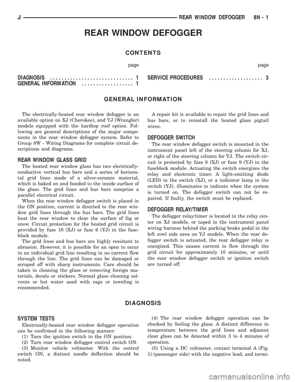
REAR WINDOW DEFOGGER
CONTENTS
page page
DIAGNOSIS............................. 1
GENERAL INFORMATION.................. 1SERVICE PROCEDURES................... 3
GENERAL INFORMATION
The electrically-heated rear window defogger is an
available option on XJ (Cherokee), and YJ (Wrangler)
models equipped with the hardtop roof option. Fol-
lowing are general descriptions of the major compo-
nents in the rear window defogger system. Refer to
Group 8W - Wiring Diagrams for complete circuit de-
scriptions and diagrams.
REAR WINDOW GLASS GRID
The heated rear window glass has two electrically-
conductive vertical bus bars and a series of horizon-
tal grid lines made of a silver-ceramic material,
which is baked on and bonded to the inside surface of
the glass. The grid lines and bus bars comprise a
parallel electrical circuit.
When the rear window defogger switch is placed in
the ON position, current is directed to the rear win-
dow grid lines through the bus bars. The grid lines
heat the rear window to clear the surface of fog or
snow. Circuit protection for the heated grid circuit is
provided by fuse 18 (XJ) or fuse 6 (YJ) in the fuse-
block module.
The grid lines and bus bars are highly resistant to
abrasion. However, it is possible for an open to occur
in an individual grid line resulting in no current flow
through the line. The grid lines can be damaged or
scraped off with sharp instruments. Care should be
taken in cleaning the glass or removing foreign ma-
terials, decals or stickers. Normal glass cleaning sol-
vents or hot water used with rags or toweling is
recommended.A repair kit is available to repair the grid lines and
bus bars, or to reinstall the heated glass pigtail
wires.
DEFOGGER SWITCH
The rear window defogger switch is mounted in the
instrument panel left of the steering column for XJ,
or right of the steering column for YJ. The switch cir-
cuit is protected by fuse 8 (XJ) or fuse 9 (YJ) in the
fuseblock module. Actuating the switch energizes the
relay and electronic timer. A light-emitting diode
(LED) in the switch (XJ), or a indicator lamp in the
switch (YJ), illuminates to indicate when the system
is turned on. The defogger switch can not be re-
paired. If faulty, the switch must be replaced.
DEFOGGER RELAY/TIMER
The defogger relay/timer is located in the relay cen-
ter on XJ models, or taped to the instrument panel
wiring harness behind the parking brake pedal in the
left cowl side area on YJ models. When the rear de-
fogger switch is actuated, the rear defogger relay is
energized. This causes current to flow through the
grid circuit for approximately 10 minutes, or until
the rear window defogger switch or ignition switch
are turned off.
DIAGNOSIS
SYSTEM TESTS
Electrically-heated rear window defogger operation
can be confirmed in the following manner:
(1) Turn the ignition switch to the ON position.
(2) Turn rear window defogger control switch ON.
(3) Monitor vehicle voltmeter. With the control
switch ON, a distinct needle deflection should be
noted.(4) The rear window defogger operation can be
checked by feeling the glass. A distinct difference in
temperature between the grid lines and adjacent
clear glass can be detected within 3 to 4 minutes of
operation.
(5) Using a DC voltmeter, contact terminal A (Fig.
1) (passenger side) with the negative lead, and termi-
JREAR WINDOW DEFOGGER 8N - 1