1995 JEEP XJ brake
[x] Cancel search: brakePage 218 of 2158
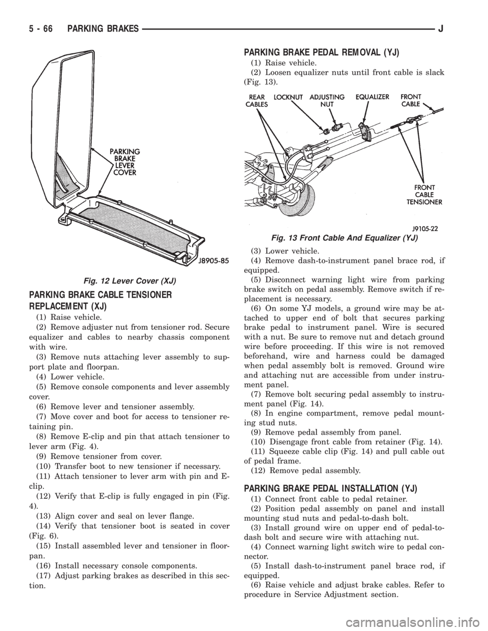
PARKING BRAKE CABLE TENSIONER
REPLACEMENT (XJ)
(1) Raise vehicle.
(2) Remove adjuster nut from tensioner rod. Secure
equalizer and cables to nearby chassis component
with wire.
(3) Remove nuts attaching lever assembly to sup-
port plate and floorpan.
(4) Lower vehicle.
(5) Remove console components and lever assembly
cover.
(6) Remove lever and tensioner assembly.
(7) Move cover and boot for access to tensioner re-
taining pin.
(8) Remove E-clip and pin that attach tensioner to
lever arm (Fig. 4).
(9) Remove tensioner from cover.
(10) Transfer boot to new tensioner if necessary.
(11) Attach tensioner to lever arm with pin and E-
clip.
(12) Verify that E-clip is fully engaged in pin (Fig.
4).
(13) Align cover and seal on lever flange.
(14) Verify that tensioner boot is seated in cover
(Fig. 6).
(15) Install assembled lever and tensioner in floor-
pan.
(16) Install necessary console components.
(17) Adjust parking brakes as described in this sec-
tion.
PARKING BRAKE PEDAL REMOVAL (YJ)
(1) Raise vehicle.
(2) Loosen equalizer nuts until front cable is slack
(Fig. 13).
(3) Lower vehicle.
(4) Remove dash-to-instrument panel brace rod, if
equipped.
(5) Disconnect warning light wire from parking
brake switch on pedal assembly. Remove switch if re-
placement is necessary.
(6) On some YJ models, a ground wire may be at-
tached to upper end of bolt that secures parking
brake pedal to instrument panel. Wire is secured
with a nut. Be sure to remove nut and detach ground
wire before proceeding. If this wire is not removed
beforehand, wire and harness could be damaged
when pedal assembly bolt is removed. Ground wire
and attaching nut are accessible from under instru-
ment panel.
(7) Remove bolt securing pedal assembly to instru-
ment panel (Fig. 14).
(8) In engine compartment, remove pedal mount-
ing stud nuts.
(9) Remove pedal assembly from panel.
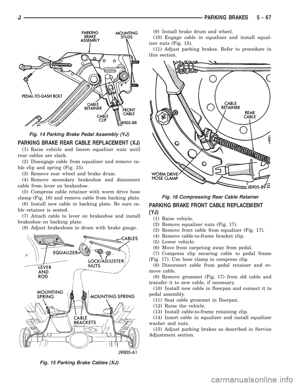
(10) Disengage front cable from retainer (Fig. 14).
(11) Squeeze cable clip (Fig. 14) and pull cable out
of pedal frame.
(12) Remove pedal assembly.
PARKING BRAKE PEDAL INSTALLATION (YJ)
(1) Connect front cable to pedal retainer.
(2) Position pedal assembly on panel and install
mounting stud nuts and pedal-to-dash bolt.
(3) Install ground wire on upper end of pedal-to-
dash bolt and secure wire with attaching nut.
(4) Connect warning light switch wire to pedal con-
nector.
(5) Install dash-to-instrument panel brace rod, if
equipped.
(6) Raise vehicle and adjust brake cables. Refer to
procedure in Service Adjustment section.
Fig. 12 Lever Cover (XJ)
Fig. 13 Front Cable And Equalizer (YJ)
5 - 66 PARKING BRAKESJ
Page 219 of 2158
PARKING BRAKE REAR CABLE REPLACEMENT (XJ)
(1) Raise vehicle and loosen equalizer nuts until
rear cables are slack.
(2) Disengage cable from equalizer and remove ca-
ble clip and spring (Fig. 15).
(3) Remove rear wheel and brake drum.
(4) Remove secondary brakeshoe and disconnect
cable from lever on brakeshoe.
(5) Compress cable retainer with worm drive hose
clamp (Fig. 16) and remove cable from backing plate.
(6) Install new cable in backing plate. Be sure ca-
ble retainer is seated.
(7) Attach cable to lever on brakeshoe and install
brakeshoe on backing plate.
(8) Adjust brakeshoes to drum with brake gauge.(9) Install brake drum and wheel.
(10) Engage cable in equalizer and install equal-
izer nuts (Fig. 15).
(11) Adjust parking brakes. Refer to procedure in
this section.
PARKING BRAKE FRONT CABLE REPLACEMENT
(YJ)
(1) Raise vehicle.
(2) Remove equalizer nuts (Fig. 17).
(3) Remove front cable from equalizer (Fig. 17).
(4) Remove cable-to-frame bracket clip.
(5) Lower vehicle.
(6) Move front carpeting away from pedal.
(7) Compress clip securing cable to pedal frame
(Fig. 17). Use hose clamp to compress clip.
(8) Disconnect cable from pedal retainer and re-
move cable.
(9) Remove grommet (Fig. 17) from old cable and
transfer it to new cable, if necessary.
(10) Install new cable in floorpan and connect it to
pedal assembly.
(11) Seat cable grommet in floorpan.
(12) Raise the vehicle.
(13) Install cable-to-frame retaining clip.
(14) Insert cable in equalizer and install equalizer
washer and nuts.
(15) Adjust parking brakes as described in Service
Adjustment section.
Fig. 14 Parking Brake Pedal Assembly (YJ)
Fig. 15 Parking Brake Cables (XJ)
Fig. 16 Compressing Rear Cable Retainer
JPARKING BRAKES 5 - 67
Page 220 of 2158
PARKING BRAKE REAR CABLE REPLACEMENT (YJ)
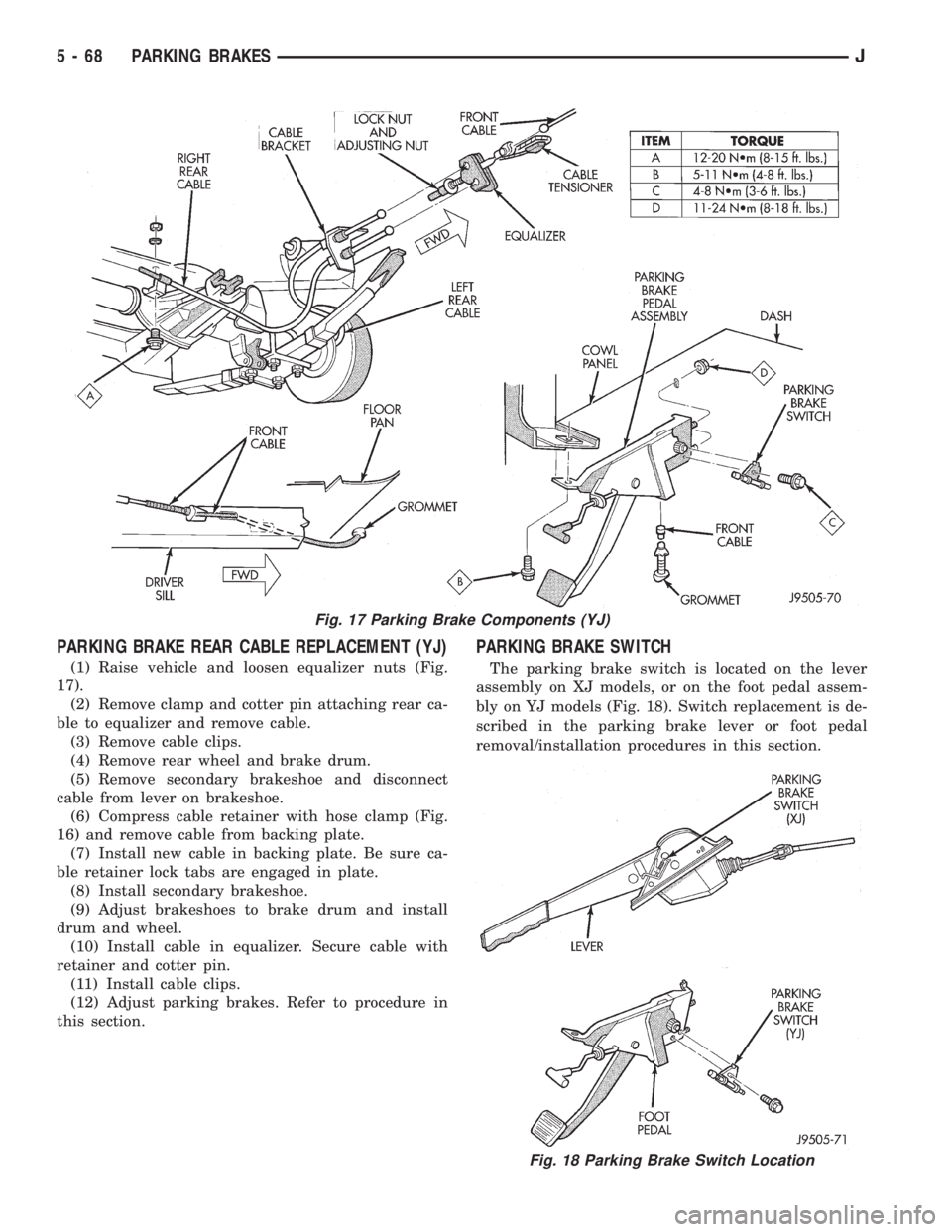
(1) Raise vehicle and loosen equalizer nuts (Fig.
17).
(2) Remove clamp and cotter pin attaching rear ca-
ble to equalizer and remove cable.
(3) Remove cable clips.
(4) Remove rear wheel and brake drum.
(5) Remove secondary brakeshoe and disconnect
cable from lever on brakeshoe.
(6) Compress cable retainer with hose clamp (Fig.
16) and remove cable from backing plate.
(7) Install new cable in backing plate. Be sure ca-
ble retainer lock tabs are engaged in plate.
(8) Install secondary brakeshoe.
(9) Adjust brakeshoes to brake drum and install
drum and wheel.
(10) Install cable in equalizer. Secure cable with
retainer and cotter pin.
(11) Install cable clips.
(12) Adjust parking brakes. Refer to procedure in
this section.
PARKING BRAKE SWITCH
The parking brake switch is located on the lever
assembly on XJ models, or on the foot pedal assem-
bly on YJ models (Fig. 18). Switch replacement is de-
scribed in the parking brake lever or foot pedal
removal/installation procedures in this section.
Fig. 17 Parking Brake Components (YJ)
Fig. 18 Parking Brake Switch Location
5 - 68 PARKING BRAKESJ
Page 221 of 2158
PARKING BRAKE CABLE TENSIONER ADJUSTMENT
(XJ/YJ)
Parking brake adjustment is only necessary
when the tensioner, or a cable has been re-
placed or disconnected for service. When ad-
justment is necessary, perform adjustment only
as described in the following procedure. This is
necessary to avoid faulty parking brake opera-
tion.
(1) Raise vehicle.
(2) Back off tensioner adjusting nut to create slack
in cables.
(3) Remove rear wheel/tire assemblies and remove
brake drums.
(4) Check rear brakeshoe adjustment with stan-
dard brake gauge. Also check condition of brake parts
as follows:
(a) Replace worn parts if necessary.Excessive
shoe-to-drum clearance, or worn brake com-
ponents will result in faulty parking brake
adjustment and operation.
(b) Verify that parking brake cables operate
freely and are not binding, or seized. Replace faulty
cables, before proceeding.
(c) Adjust rear brakeshoes shoes to drum.
(5) Reinstall brake drums and wheel/tire assem-
blies after brakeshoe adjustment is complete.
(6) Lower vehicle enough for access to parking
brake lever or foot pedal.Then fully apply parking
brakes. Leave brakes applied until adjustment
is complete.(7) Raise vehicle again.
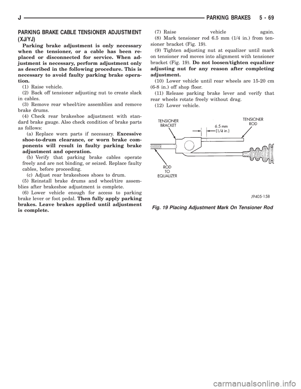
(8) Mark tensioner rod 6.5 mm (1/4 in.) from ten-
sioner bracket (Fig. 19).
(9) Tighten adjusting nut at equalizer until mark
on tensioner rod moves into alignment with tensioner
bracket (Fig. 19).Do not loosen/tighten equalizer
adjusting nut for any reason after completing
adjustment.
(10) Lower vehicle until rear wheels are 15-20 cm
(6-8 in.) off shop floor.
(11) Release parking brake lever and verify that
rear wheels rotate freely without drag.
(12) Lower vehicle.
Fig. 19 Placing Adjustment Mark On Tensioner Rod
JPARKING BRAKES 5 - 69
Page 222 of 2158
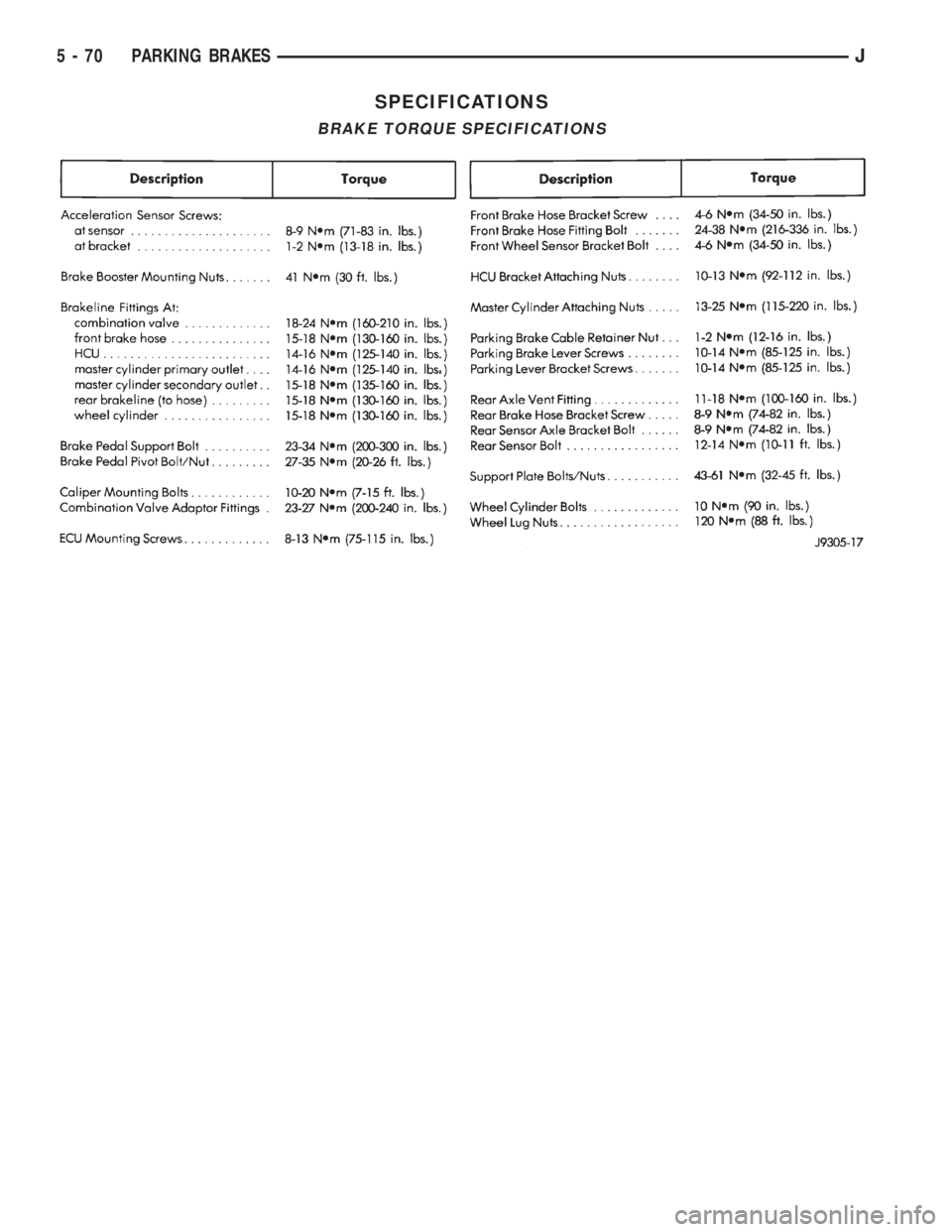
SPECIFICATIONS
BRAKE TORQUE SPECIFICATIONS
5 - 70 PARKING BRAKESJ
Page 223 of 2158
CLUTCH
CONTENTS
page page
CLUTCH DIAGNOSIS...................... 3
CLUTCH SERVICE....................... 10GENERAL INFORMATION.................. 1
GENERAL INFORMATION
INDEX
page page
Clutch Components........................ 1
Clutch Linkage Fluid........................ 1Clutch Operation........................... 2
Hydraulic Linkage Components................ 1
CLUTCH COMPONENTS
The clutch mechanism in XJ/YJ models consists of
a single, dry-type disc and a diaphragm style clutch
cover. A hydraulic linkage is used to operate the
clutch release bearing and fork.
A needle-type pilot bearing supports the transmis-
sion input shaft in the crankshaft. A sleeve type re-
lease bearing is used to engage and disengage the
clutch cover pressure plate.
The release bearing is operated by a release fork in
the clutch housing. The fork pivots on a ball stud
mounted in the housing. The release fork is actuated
by a hydraulic slave cylinder mounted in the hous-
ing. The slave cylinder is operated by a clutch master
cylinder mounted on the dash panel. The cylinder
push rod is connected to the clutch pedal.
The clutch disc has cushion springs in the disc hub.
The clutch disc facing is riveted to the hub. The fac-
ing is made from a non-asbestos material. The clutch
cover pressure plate is a diaphragm type with a one-
piece spring and multiple release fingers. The pres-
sure plate release fingers are preset during
manufacture and are not adjustable.
HYDRAULIC LINKAGE COMPONENTS
The hydraulic linkage consists of a clutch master
cylinder with integral reservoir, a clutch slave cylin-
der and an interconnecting fluid line.The clutch master cylinder push rod is connected to
the clutch pedal. The slave cylinder push rod is con-
nected to the clutch release fork. The master cylinder
is mounted on the driver side of the dash panel ad-
jacent to the brake master cylinder and booster as-
sembly. This positioning is similar for both left and
right hand drive models.
CLUTCH LINKAGE FLUID
The integral clutch master cylinder reservoir, slave
cylinder and fluid lines are prefilled with fluid prior
to assembly operations.
The hydraulic system should not require additional
fluid under normal circumstances. In fact,the reser-
voir fluid level will actually increase as normal
clutch wear occurs. For this reason, it is impor-
tant to avoid overfilling, or removing fluid from
the reservoir. This will cause clutch release
problems.
If inspection or diagnosis indicates additional fluid
may be needed, use Mopar brake fluid, or an equiv-
alent meeting standards SAE J1703 and DOT 3. Do
not use any other type of fluid.
JCLUTCH 6 - 1
Page 237 of 2158
If inspection or diagnosis indicates additional fluid
may be needed, use Mopar brake fluid, or an equiv-
alent meeting standards SAE J1703 and DOT 3. Do
not use any other type of fluid.
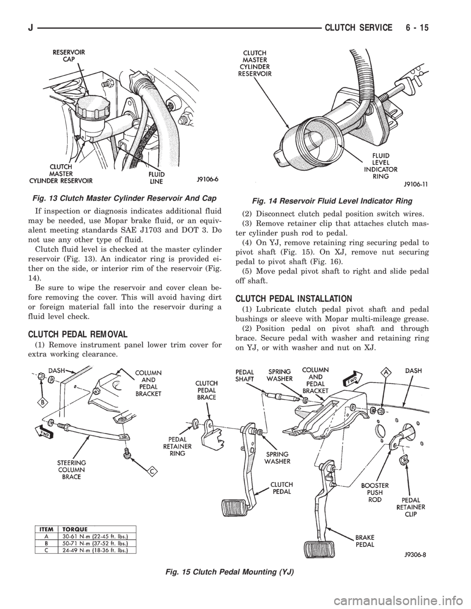
Clutch fluid level is checked at the master cylinder
reservoir (Fig. 13). An indicator ring is provided ei-
ther on the side, or interior rim of the reservoir (Fig.
14).
Be sure to wipe the reservoir and cover clean be-
fore removing the cover. This will avoid having dirt
or foreign material fall into the reservoir during a
fluid level check.
CLUTCH PEDAL REMOVAL
(1) Remove instrument panel lower trim cover for
extra working clearance.(2) Disconnect clutch pedal position switch wires.
(3) Remove retainer clip that attaches clutch mas-
ter cylinder push rod to pedal.
(4) On YJ, remove retaining ring securing pedal to
pivot shaft (Fig. 15). On XJ, remove nut securing
pedal to pivot shaft (Fig. 16).
(5) Move pedal pivot shaft to right and slide pedal
off shaft.
CLUTCH PEDAL INSTALLATION
(1) Lubricate clutch pedal pivot shaft and pedal
bushings or sleeve with Mopar multi-mileage grease.
(2) Position pedal on pivot shaft and through
brace. Secure pedal with washer and retaining ring
on YJ, or with washer and nut on XJ.
Fig. 13 Clutch Master Cylinder Reservoir And CapFig. 14 Reservoir Fluid Level Indicator Ring
Fig. 15 Clutch Pedal Mounting (YJ)
JCLUTCH SERVICE 6 - 15
Page 244 of 2158
EXAMPLES:
²If the lamp (Figs. 5 or 6) flashes 1 time, pauses
and flashes 2 more times, a flashing Diagnostic Trou-
ble Code (DTC) number 12 is indicated. If this code is
observed, it is indicating that the battery has been
disconnected within the last 50 key-on cycles. It
could also indicate that battery voltage has been dis-
connected to the PCM. In either case, other DTC's
may have been erased.
²If the lamp flashes 1 time, pauses and flashes 7
more times, a flashing Diagnostic Trouble Code
(DTC) number 17 is indicated.
²If the lamp flashes 3 times, pauses and flashes 5
more times, a flashing Diagnostic Trouble Code
(DTC) number 35 is indicated.
After any stored DTC information has been ob-
served, the display will end with a flashing DTC
number 55. This will indicate the end of all stored in-
formation.
ERASING TROUBLE CODES
After the problem has been repaired, the DRB scan
tool must be used to erase a DTC. Refer to the ap-
propriate Powertrain Diagnostic Procedures service
manual for operation of the DRB scan tool.
DRB SCAN TOOL
For operation of the DRB scan tool, refer to the ap-
propriate Powertrain Diagnostic Procedures service
manual.
PRELIMINARY CHECKS
ENGINE COOLING SYSTEM OVERHEATING
Establish what driving conditions caused the com-
plaint. Abnormal loads on the cooling system such as
the following may be the cause.
1. PROLONGED IDLE, VERY HIGH AMBIENT
TEMPERATURE, SLIGHT TAIL WIND AT IDLE,
SLOW TRAFFIC, TRAFFIC JAMS, HIGH
SPEED, OR STEEP GRADES:
Driving techniques that avoid overheating are:
²Idle with A/C off when temperature gauge is at
end of normal range.
²Increasing engine speed for more air flow is recom-
mended.
2. TRAILER TOWING:
Consult Trailer Towing section of owners manual.
Do not exceed limits.
3. AIR CONDITIONING; ADD-ON OR AFTER
MARKET:
A maximum cooling package should have been or-
dered with vehicle if add-on or after market A/C is
installed. If not, maximum cooling system compo-
nents should be installed for model involved per
manufacturer's specifications.
4. RECENT SERVICE OR ACCIDENT REPAIR:
Determine if any recent service has been performed
on vehicle that may effect cooling system. This may
be:
²Engine adjustments (incorrect timing)
²Slipping engine accessory drive belt(s)
²Brakes (possibly dragging)
²Changed parts (incorrect water pump rotating in
wrong direction)
²Reconditioned radiator or cooling system refilling
(possibly under-filled or air trapped in system).
If investigation reveals none of the previous
items as a cause for an engine overheating com-
plaint, refer to following Cooling System Diag-
nosis charts.
These charts are to be used as a quick-reference
only. Refer to the group text for information.
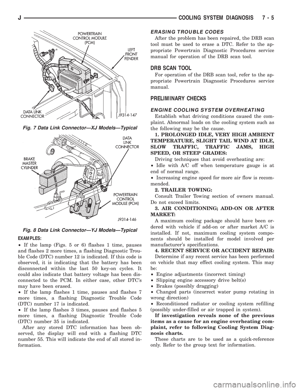
Fig. 7 Data Link ConnectorÐXJ ModelsÐTypical
Fig. 8 Data Link ConnectorÐYJ ModelsÐTypical
JCOOLING SYSTEM DIAGNOSIS 7 - 5