1995 JEEP XJ brake
[x] Cancel search: brakePage 380 of 2158
INSTRUMENT PANEL AND GAUGESÐYJ
CONTENTS
page page
INSTRUMENT PANEL AND GAUGESÐYJ..... 22
DIAGNOSIS............................ 23
GENERAL INFORMATION................. 20SERVICE PROCEDURES.................. 31
SPECIFICATIONS........................ 39
GENERAL INFORMATION
Following are general descriptions of major instru-
ment panel components. Refer to Group 8W - Wiring
Diagrams for complete circuit descriptions and dia-
grams.
INSTRUMENT PANEL
Modular instrument panel construction allows all
gauges and controls to be serviced from the front of
the panel. In addition, most instrument panel wiring
and heater components can be accessed without com-
plete instrument panel removal.
Removal of the left instrument cluster bezel allows
access to the main cluster assembly and most
switches. Removal of the center cluster bezel allows
access to the gauge package cluster assembly, the
heater controls, and the radio. Removal of the cluster
assemblies allows access to the individual gauges, il-
lumination and indicator lamp bulbs, printed cir-
cuits, and most wiring.
INSTRUMENT CLUSTERS
The instrument cluster used on YJ (Wrangler) mod-
els consists of two separate assemblies. The main
cluster assembly is located on the left side of the in-
strument panel, centered over the steering column
opening. The gauge package cluster assembly is lo-
cated near the center of the instrument panel. Each
cluster assembly is served by a separate printed cir-
cuit and wiring connector. Some variations of each
cluster exist due to optional equipment and regula-
tory requirements.
The main cluster assembly includes a speedometer/
odometer/trip odometer and a tachometer. It also in-
cludes provisions for the following indicator lamps:
²anti-lock brake system lamp
²brake warning lamp
²headlamp high beam indicator lamp
²malfunction indicator (Check Engine) lamp
²seat belt reminder lamp²turn signal indicator lamps
²upshift indicator lamp.
The gauge package cluster assembly includes a
four-wheel drive indicator lamp and the following
gauges:
²coolant temperature gauge
²fuel gauge
²oil pressure gauge
²voltmeter.
GAUGES
With the ignition switch in the ON or START posi-
tion, voltage is supplied to all gauges through the
two cluster printed circuits. With the ignition switch
in the OFF position, voltage is not supplied to the
gauges. A gauge pointer may remain within the
gauge scale after the ignition switch is OFF. How-
ever, the gauges do not accurately indicate any vehi-
cle condition unless the ignition switch is ON.
All gauges except the odometer are air core mag-
netic units. Two fixed electromagnetic coils are lo-
cated within the gauge. These coils are wrapped at
right angles to each other around a movable perma-
nent magnet. The movable magnet is suspended
within the coils on one end of a shaft. The gauge nee-
dle is attached to the other end of the shaft.
One of the coils has a fixed current flowing through
it to maintain a constant magnetic field strength.
Current flow through the second coil changes, which
causes changes in its magnetic field strength. The
current flowing through the second coil can be
changed by:
²a variable resistor-type sending unit (fuel level,
coolant temperature, or oil pressure)
²changes in electrical system voltage (voltmeter)
²electronic control circuitry (speedometer/odometer,
tachometer).
8E - 24 INSTRUMENT PANEL AND GAUGESÐYJJ
Page 381 of 2158

The gauge needle moves as the movable permanent
magnet aligns itself to the changing magnetic fields
created around it by the electromagnets.
COOLANT TEMPERATURE GAUGE
The coolant temperature gauge gives an indication
of engine coolant temperature. The coolant tempera-
ture sending unit is a thermistor that changes elec-
trical resistance with changes in engine coolant
temperature. High sending unit resistance causes
low coolant temperature readings. Low resistance
causes high coolant temperature readings. Sending
unit resistance values are shown in a chart in Spec-
ifications.
FUEL GAUGE
The fuel gauge gives an indication of the level of
fuel in the fuel tank. The fuel gauge sending unit has
a float attached to a swing-arm in the fuel tank. The
float moves up or down within the fuel tank as fuel
level changes. As the float moves, an electrical con-
tact on the swing-arm wipes across a resistor coil,
which changes sending unit resistance. High sending
unit resistance causes high fuel level readings. Low
resistance causes low fuel level readings. Sending
unit resistance values are shown in a chart in Spec-
ifications.
OIL PRESSURE GAUGE
The oil pressure gauge gives an indication of en-
gine oil pressure. The combination oil pressure send-
ing unit contains a flexible diaphragm. The
diaphragm moves in response to changes in engine
oil pressure. As the diaphragm moves, sending unit
resistance increases or decreases. High resistance on
the gauge side of the sending unit causes high oil
pressure readings. Low resistance causes low oil
pressure readings. Sending unit resistance values are
shown in a chart in Specifications.
SPEEDOMETER/ODOMETER
The speedometer/odometer give an indication of ve-
hicle speed and travel distance. The speedometer re-
ceives a vehicle speed pulse signal from the Vehicle
Speed Sensor (VSS). An electronic integrated circuit
contained within the speedometer reads and analyzes
the pulse signal. It then adjusts the ground path re-
sistance of one electromagnet in the gauge to control
needle movement. It also sends signals to an electric
stepper motor to control movement of the odometer
number rolls. Frequency values for the pulse signal
are shown in a chart in Specifications.
The VSS is mounted to an adapter near the trans-
fer case output shaft. The sensor is driven through
the adapter by a speedometer pinion gear. The
adapter and pinion vary with transmission, axle ratio
and tire size. Refer to Group 21 - Transmission and
Transfer Case for more information.
TACHOMETER
The tachometer gives an indication of engine speed
in Revolutions-Per-Minute (RPM). With the engine
running, the tachometer receives an engine speed
pulse signal from the Powertrain Control Module
(PCM). An electronic integrated circuit contained
within the tachometer reads and analyzes the pulse
signal. It then adjusts the ground path resistance of
one electromagnet in the gauge to control needle
movement. Frequency values for the pulse signal are
shown in a chart in Specifications.
TRIP ODOMETER
The trip odometer is driven by the same electronic
integrated circuit as the speedometer/odometer. How-
ever, by depressing the trip odometer reset knob on
the face of the speedometer, the trip odometer can be
reset to zero. The trip odometer is serviced only as a
part of the speedometer/odometer gauge assembly.
VOLTMETER
The voltmeter is connected in parallel with the bat-
tery. With the ignition switch ON, the voltmeter in-
dicates battery or generator output voltage,
whichever is greater.
INDICATOR LAMPS
All indicator lamps, except the four-wheel drive in-
dicator, are located in the main cluster tell-tale area
above the steering column opening. Each of the
lamps is served by the main cluster printed circuit
and cluster connector. The four-wheel drive indicator
lamp is located in the gauge package cluster and is
served by the gauge package printed circuit and clus-
ter connector.
Up to eleven indicator lamps can be found in the
tell-tale area of the main cluster. These lamps are ar-
ranged in two rows, with six lamps in the upper row
and five lamps in the lower row.
ANTI-LOCK BRAKE SYSTEM LAMP
The Anti-Lock Brake System (ABS) lamp is
switched to ground by the ABS module. The module
lights the lamp when the ignition switch is turned to
the START position as a bulb test. The lamp will
stay on for 3 to 5 seconds after vehicle start-up to in-
dicate a system self-test is in process. If the lamp re-
mains on after start-up, or comes on and stays on
while driving, it may indicate that the ABS module
has detected a system malfunction or that the system
has become inoperative. Refer to Group 5 - Brakes
for more information.
BRAKE WARNING LAMP
The brake warning lamp warns the driver that the
parking brake is applied or that the pressures in the
two halves of the split brake hydraulic system are
unequal. With the ignition switch turned ON, battery
JINSTRUMENT PANEL AND GAUGESÐYJ 8E - 25
Page 382 of 2158
voltage is supplied to one side of the indicator bulb. A
ground path for the bulb is provided by 3 switches.
The bulb will light when:
²the brake warning switch is closed (indicating un-
equal brake system hydraulic pressures possibly due
to brake fluid leakage)
²the ignition switch is in the START position (bulb
test)
²the parking brake switch is closed (parking brake
is applied).
Refer to Group 5 - Brakes for more information.
FOUR-WHEEL DRIVE INDICATOR LAMP
This lamp lights when the transfer case is engaged
in the 4H or 4L position. Voltage is supplied to one
side of the indicator bulb. A switch on the front axle
disconnect housing is connected to the other side of
the indicator bulb. When the switch is closed, a path
to ground is provided and the indicator bulb lights.
HEADLAMP HIGH BEAM INDICATOR LAMP
The high beam indicator lamp is controlled by the
headlamp dimmer switch. One side of the indicator
bulb is grounded at all times. The other side of the
bulb receives battery feed through the contacts of the
dimmer switch when the turn signal switch lever is
actuated to turn the headlamp high beams on. Refer
to Group 8L - Lamps for more information.
MALFUNCTION INDICATOR LAMP
The CHECK ENGINE or Malfunction Indicator
Lamp (MIL) lights each time the ignition switch is
turned ON, and stays on for 3 seconds as a bulb test.
If the Powertrain Control Module (PCM) receives an
incorrect signal or no signal from certain fuel or
emission system related circuits or components, the
lamp is turned on. This will indicate that the PCM
has recorded a Diagnostic Trouble Code (DTC) in
electronic memory for a circuit or component mal-
function. Refer to Group 14 - Fuel System for more
information.
SEAT BELT REMINDER LAMP
The seat belt reminder lamp lights for 4 to 8 sec-
onds after the ignition switch is turned to the ON po-sition. A timer in the chime/buzzer module controls
ignition-switched battery feed to the lamp. Refer to
Group 8U - Chime/Buzzer Warning Systems for more
information.
TURN SIGNAL INDICATOR LAMPS
The left and right turn signal indicator lamps are
controlled by the turn signal and hazard warning
switches. One side of the bulb for each lamp is
grounded at all times. The other side of the bulb re-
ceives battery feed through the contacts of the turn
signal switch, when the turn signal lever or hazard
warning button are actuated. Refer to Group 8J -
Turn Signal and Hazard Warning Systems for more
information.
UPSHIFT INDICATOR LAMP
Vehicles equipped with manual transmissions have
an optional upshift indicator lamp. Ground feed for
the lamp is switched by the Powertrain Control Mod-
ule (PCM). The lamp lights to indicate when the
driver should shift to the next highest gear for best
fuel economy. The PCM will turn the lamp off after 3
to 5 seconds if the upshift is not performed. The lamp
will remain off until the vehicle stops accelerating
and is brought back to the range of lamp operation,
or until the transmission is shifted into another gear.
The indicator lamp is normally on when the igni-
tion switch is turned ON and is turned off when the
engine is started. The lamp will be turned on during
vehicle operation according to engine speed and load.
CLUSTER ILLUMINATION LAMPS
All cluster illumination lamps receive battery feed
from the instrument lamps fuse in the fuseblock
module through the panel dimmer switch. When the
park or headlamps are on, the cluster illumination
lamps light. Illumination brightness can be adjusted
by rotating the panel dimmer thumb-wheel, which is
next to the headlamp switch.
8E - 26 INSTRUMENT PANEL AND GAUGESÐYJJ
Page 388 of 2158
INDICATOR LAMPS
If an individual indicator lamp is inoperative, see
the diagnostic procedure under the heading for that
lamp. If more than one indicator lamp or a combina-
tion of lamps and gauges in the main cluster or the
gauge package cluster is inoperative, see Gauges in
this section for diagnosis.
ANTI-LOCK BRAKE SYSTEM LAMP
The diagnosis found here addresses an inoperative
lamp condition. If the ABS lamp stays on with the ig-
nition switch in the ON position, or comes on and
stays on while driving, refer to Group 5 - Brakes for
diagnosis. If no ABS problem is found, the following
procedure will help locate a short or open in the ABS
lamp circuit.
(1) Disconnect battery negative cable. Remove left
instrument cluster bezel and main cluster assembly.
Disconnect ABS control module connector.
(2) Install a jumper wire between cavity 6 of clus-
ter connector and a good ground. Connect battery
negative cable. Turn ignition switch to ON. Lamp
should light. If OK, remove jumper wire and go to
next step. If not OK, replace bulb.
(3) Turn ignition switch to OFF. Disconnect battery
negative cable and unplug cluster connector. Check
for continuity between cavity 6 of cluster connector
and a good ground. There should be no continuity. If
OK, go to next step. If not OK, repair short circuit as
required.
(4) Check continuity between cavity 6 of cluster
connector and cavity 52 of ABS control module con-
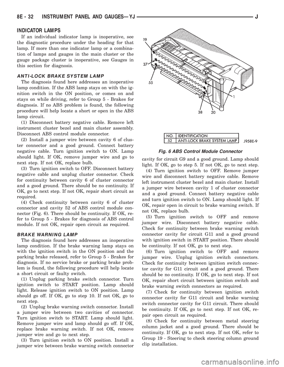
nector (Fig. 6). There should be continuity. If OK, re-
fer to Group 5 - Brakes for diagnosis of ABS control
module. If not OK, repair open circuit as required.
BRAKE WARNING LAMP
The diagnosis found here addresses an inoperative
lamp condition. If the brake warning lamp stays on
with the ignition switch in the ON position and the
parking brake released, refer to Group 5 - Brakes for
diagnosis. If no service brake or parking brake prob-
lem is found, the following procedure will help locate
a short circuit or faulty switch.
(1) Unplug parking brake switch connector. Turn
ignition switch to START position. Lamp should
light. Release ignition switch to ON position. Lamp
should go off. If OK, go to step 10. If not OK, go to
next step.
(2) Unplug brake warning switch connector. Install
a jumper wire between two cavities of connector.
Turn ignition switch to START. Lamp should light.
Remove jumper wire and lamp should go off. If OK,
replace brake warning switch. If not OK, remove
jumper wire and go to next step.
(3) Turn ignition switch to ON position. Install a
jumper wire between brake warning switch connectorcavity for circuit G9 and a good ground. Lamp should
light. If OK, go to step 5. If not OK, go to next step.
(4) Turn ignition switch to OFF. Remove jumper
wire and disconnect battery negative cable. Remove
left instrument cluster bezel and main cluster. Install
a jumper wire between cavity 1 of cluster connector
and a good ground. Connect battery negative cable
and turn ignition switch to ON. Lamp should light. If
OK, repair open in circuit to brake warning switch. If
not OK, replace bulb.
(5) Turn ignition switch to OFF and remove
jumper wire. Disconnect battery negative cable.
Check for continuity between brake warning switch
connector cavity for circuit G11 and a good ground
with ignition switch in START position. There should
be continuity. If not OK, go to next step.
(6) Turn ignition switch to OFF and remove
jumper wire. Unplug ignition switch connectors.
Check for continuity between ignition switch connec-
tor cavity for G11 circuit and a good ground. There
should be no continuity. If OK, go to next step. If not
OK, repair short circuit between ignition switch and
brake warning switch connectors as required.
(7) Check for continuity between ignition switch
connector cavity for G11 circuit and brake warning
switch connector cavity for G11 circuit. There should
be continuity. If OK, go to next step. If not OK, re-
pair open circuit as required.
(8) Check for continuity between metal steering
column jacket and a good ground. There should be
continuity. If OK, go to next step. If not OK, refer to
Group 19 - Steering to check steering column ground
clip installation.
Fig. 6 ABS Control Module Connector
8E - 32 INSTRUMENT PANEL AND GAUGESÐYJJ
Page 389 of 2158
(9) Turn ignition switch to START position and
hold there. Check for continuity between terminal for
circuit G11 of ignition switch and a good ground.
There should be continuity. If not OK, replace igni-
tion switch.
(10) Unplug brake warning switch connector.
Check for continuity between parking brake switch
connector and a good ground. There should be no
continuity. If OK, go to next step. If not OK, repair
short circuit as required.
(11) Check for continuity between parking brake
switch connector and brake warning switch connector
cavity for circuit G11. There should be continuity. If
OK, replace parking brake switch. If not OK, repair
open circuit to brake warning switch as required.
FOUR-WHEEL DRIVE INDICATOR LAMP
(1) Apply parking brake, start engine, vehicle in
4WD Lock or 4WD.
(2) Unplug switch and touch harness side of wire
to ground. Lamp should light. If OK, check switch
operation, replace if bad. If bulb is OK, repair open
to indicator.
HEADLAMP HIGH BEAM INDICATOR LAMP
(1) Check that headlamp high beams are func-
tional. If OK, go to next step. If not OK, refer to
Group 8L - Lamps for diagnosis of headlamp system.
(2) Disconnect battery negative cable. Remove left
instrument cluster bezel and main cluster assembly.
Unplug cluster connector. Connect battery negative
cable. Turn headlamps on and select high beam.
Check for battery voltage at cavity 17 of cluster con-
nector. If OK, replace indicator bulb. If not OK, re-
pair circuit to headlamp dimmer switch as required.
MALFUNCTION INDICATOR LAMP
The diagnosis found here addresses an inoperative
lamp condition. If the lamp comes on and stays on
with engine running, refer to Group 14 - Fuel System
for diagnosis. If no fuel or emission system problem
is found, the following procedure will help locate a
short or open in the lamp circuit.
(1) Disconnect battery negative cable. Unplug PCM
connector. Install a jumper wire from cavity 32 of
PCM connector (Fig. 5) to a good ground. Connect
battery negative cable. Turn ignition switch to ON.
Lamp should light. Remove jumper wire and lamp
should go OFF. If OK, refer to Powertrain Diagnostic
Procedures to check PCM. If not OK, go to next step.
(2) Turn ignition switch to OFF. Disconnect battery
negative cable. Remove left instrument cluster bezel
and main cluster assembly. Install a jumper wire
from cavity 2 of cluster connector to a good ground.
Connect battery negative cable. Turn ignition switch
to ON. Lamp should light. If OK, go to next step. If
not OK, replace bulb.(3) Turn ignition switch to OFF. Disconnect battery
negative cable. Unplug cluster connector. Check for
continuity between cavity 2 of cluster connector and
a good ground. There should be no continuity. If OK,
go to next step. If not OK, repair short circuit to
PCM as required.
(4) Check continuity between cavity 2 of cluster
connector and cavity 32 of PCM connector. There
should be continuity. If not OK, repair open circuit to
PCM as required.
SEAT BELT REMINDER LAMP
(1) Refer to Group 8U - Chime/Buzzer Warning
Systems to check chime/buzzer module operation. If
OK, go to next step. If not OK, replace chime/buzzer
module.
(2) Disconnect battery negative cable. Remove left
instrument cluster bezel and main cluster assembly.
Unplug cluster connector. Check for continuity be-
tween cavity 20 of cluster connector and a good
ground. There should be continuity. If OK, plug clus-
ter connector back into cluster and go to next step. If
not OK, repair open circuit to ground as required.
(3) Connect battery negative cable. Install a
jumper wire between a 12-volt battery feed and cav-
ity 16 of cluster connector. Lamp should light. If OK,
go to next step. If not OK, replace bulb.
(4) Disconnect battery negative cable. Unplug
chime/buzzer module from fuseblock module. Unplug
cluster connector. Check for continuity between cav-
ity 16 of cluster connector and a good ground. There
should be no continuity. If OK, go to next step. If not
OK, repair short circuit to chime/buzzer module as
required.
(5) Check continuity between cavity 16 of cluster
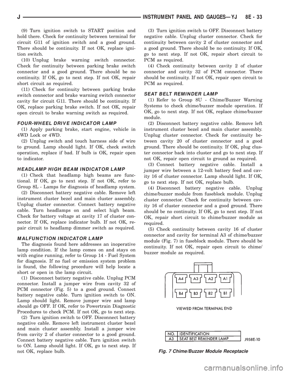
connector and cavity for terminal A3 of chime/buzzer
module (Fig. 7) in fuseblock module. There should be
continuity. If not OK, repair open circuit to chime/
buzzer module as required.
Fig. 7 Chime/Buzzer Module Receptacle
JINSTRUMENT PANEL AND GAUGESÐYJ 8E - 33
Page 406 of 2158
SERVICE PROCEDURES
RADIO REMOVE/INSTALL - XJ
(1) Disconnect battery negative cable.
(2) Remove upper and lower steering column
shrouds and steering column to instrument panel be-
zel gap hider. If equipped with tilt steering, apply
tape to tilt mechanism on top of steering column to
protect instrument panel bezel from damage during
removal.
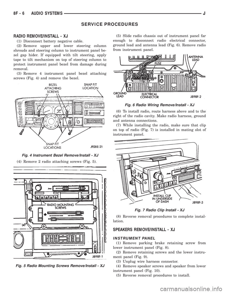
(3) Remove 4 instrument panel bezel attaching
screws (Fig. 4) and remove the bezel.
(4) Remove 2 radio attaching screws (Fig. 5).(5) Slide radio chassis out of instrument panel far
enough to disconnect radio electrical connector,
ground lead and antenna lead (Fig. 6). Remove radio
from instrument panel.
(6) To install radio, route harness above and to the
right of the radio cavity. Make radio harness, ground
and antenna connections.
(7) While installing the radio, make sure that clip
on top of radio (Fig. 7) is installed in mating slot of
instrument panel.
(8) Reverse removal procedures to complete instal-
lation.
SPEAKERS REMOVE/INSTALL - XJ
INSTRUMENT PANEL
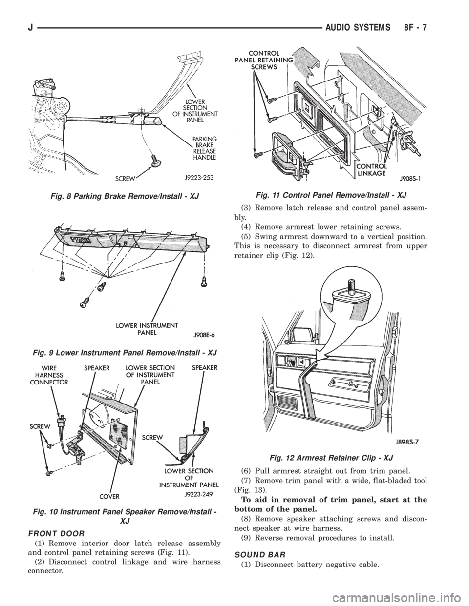
(1) Remove parking brake retaining screw from
lower instrument panel (Fig. 8).
(2) Remove retaining screws and the lower instru-
ment panel (Fig. 9).
(3) Unplug wire harness connector.
(4) Remove speaker screws and speaker from lower
instrument panel (Fig. 10).
(5) Reverse removal procedures to install.
Fig. 4 Instrument Bezel Remove/Install - XJ
Fig. 5 Radio Mounting Screws Remove/Install - XJ
Fig. 6 Radio Wiring Remove/Install - XJ
Fig. 7 Radio Clip Install - XJ
8F - 6 AUDIO SYSTEMSJ
Page 407 of 2158
FRONT DOOR
(1) Remove interior door latch release assembly
and control panel retaining screws (Fig. 11).
(2) Disconnect control linkage and wire harness
connector.(3) Remove latch release and control panel assem-
bly.
(4) Remove armrest lower retaining screws.
(5) Swing armrest downward to a vertical position.
This is necessary to disconnect armrest from upper
retainer clip (Fig. 12).
(6) Pull armrest straight out from trim panel.
(7) Remove trim panel with a wide, flat-bladed tool
(Fig. 13).
To aid in removal of trim panel, start at the
bottom of the panel.
(8) Remove speaker attaching screws and discon-
nect speaker at wire harness.
(9) Reverse removal procedures to install.
SOUND BAR
(1) Disconnect battery negative cable.
Fig. 8 Parking Brake Remove/Install - XJ
Fig. 9 Lower Instrument Panel Remove/Install - XJ
Fig. 10 Instrument Panel Speaker Remove/Install -
XJ
Fig. 11 Control Panel Remove/Install - XJ
Fig. 12 Armrest Retainer Clip - XJ
JAUDIO SYSTEMS 8F - 7
Page 409 of 2158
(9) Apply a rubberized undercoating material to
the splash panel screws.
RADIO REMOVE/INSTALL - YJ
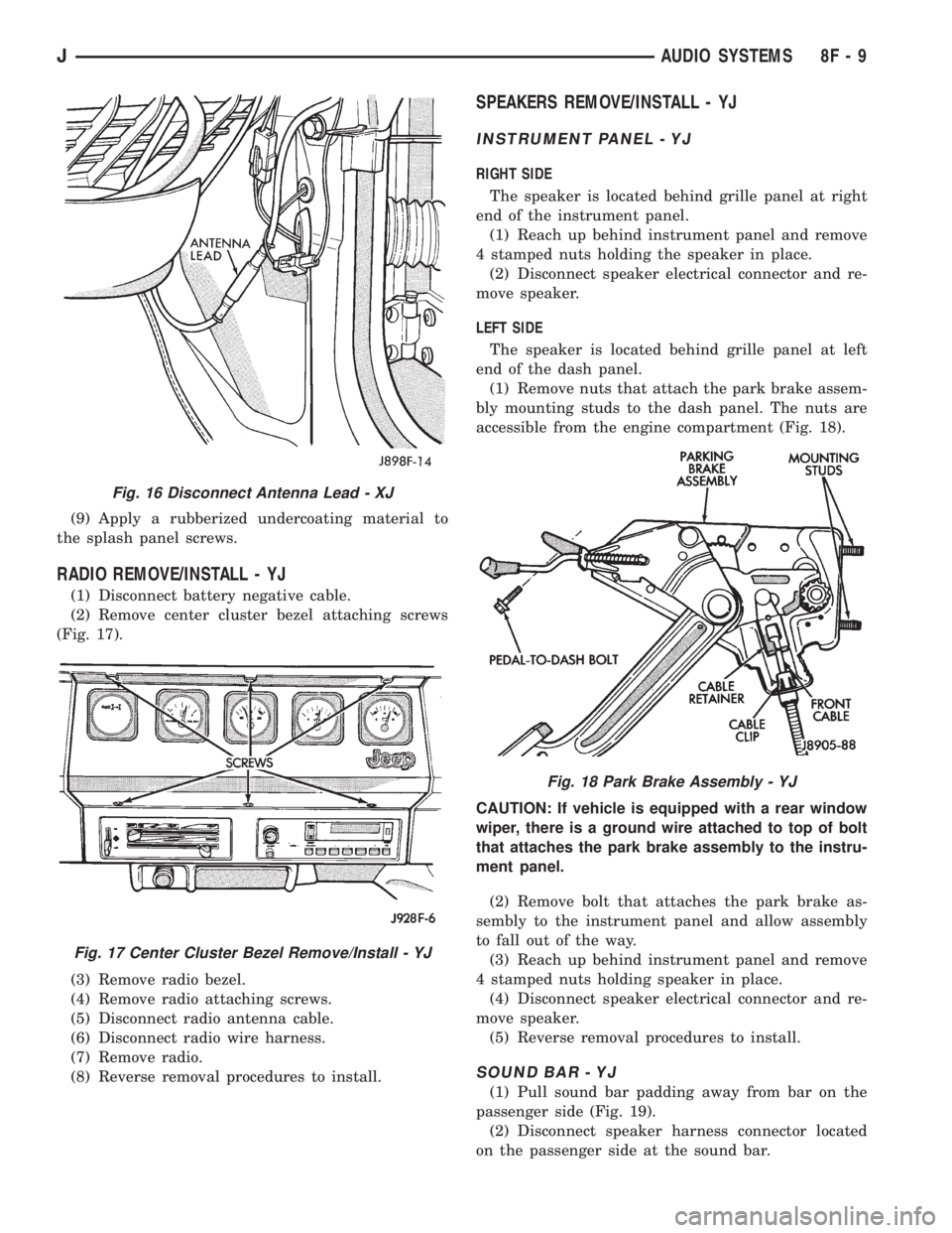
(1) Disconnect battery negative cable.
(2) Remove center cluster bezel attaching screws
(Fig. 17).
(3) Remove radio bezel.
(4) Remove radio attaching screws.
(5) Disconnect radio antenna cable.
(6) Disconnect radio wire harness.
(7) Remove radio.
(8) Reverse removal procedures to install.
SPEAKERS REMOVE/INSTALL - YJ
INSTRUMENT PANEL - YJ
RIGHT SIDE
The speaker is located behind grille panel at right
end of the instrument panel.
(1) Reach up behind instrument panel and remove
4 stamped nuts holding the speaker in place.
(2) Disconnect speaker electrical connector and re-
move speaker.
LEFT SIDE
The speaker is located behind grille panel at left
end of the dash panel.
(1) Remove nuts that attach the park brake assem-
bly mounting studs to the dash panel. The nuts are
accessible from the engine compartment (Fig. 18).
CAUTION: If vehicle is equipped with a rear window
wiper, there is a ground wire attached to top of bolt
that attaches the park brake assembly to the instru-
ment panel.
(2) Remove bolt that attaches the park brake as-
sembly to the instrument panel and allow assembly
to fall out of the way.
(3) Reach up behind instrument panel and remove
4 stamped nuts holding speaker in place.
(4) Disconnect speaker electrical connector and re-
move speaker.
(5) Reverse removal procedures to install.
SOUND BAR - YJ
(1) Pull sound bar padding away from bar on the
passenger side (Fig. 19).
(2) Disconnect speaker harness connector located
on the passenger side at the sound bar.
Fig. 16 Disconnect Antenna Lead - XJ
Fig. 17 Center Cluster Bezel Remove/Install - YJ
Fig. 18 Park Brake Assembly - YJ
JAUDIO SYSTEMS 8F - 9