1995 JEEP CHEROKEE check transmission fluid
[x] Cancel search: check transmission fluidPage 1563 of 2198
(6) Lubricate new O-ring and install it on adapter.
(7) Install solenoid wire harness and adapter in
case.
(8) Install adapter bracket and bracket bolt.
(9) Connect wires to solenoids.
(10) Install oil screen and oil pan.
TRANSMISSION VALVE BODY REMOVAL
Removal and installation are the only valve body
service procedures covered in this section. Refer to
the transmission overhaul section for valve body dis-
assembly, cleaning, inspection and reassembly.
(1) Remove oil pan plug and drain transmission
fluid.
(2) Remove oil pan and oil screen. Clean pan and
screen in solvent and dry them with compressed air.
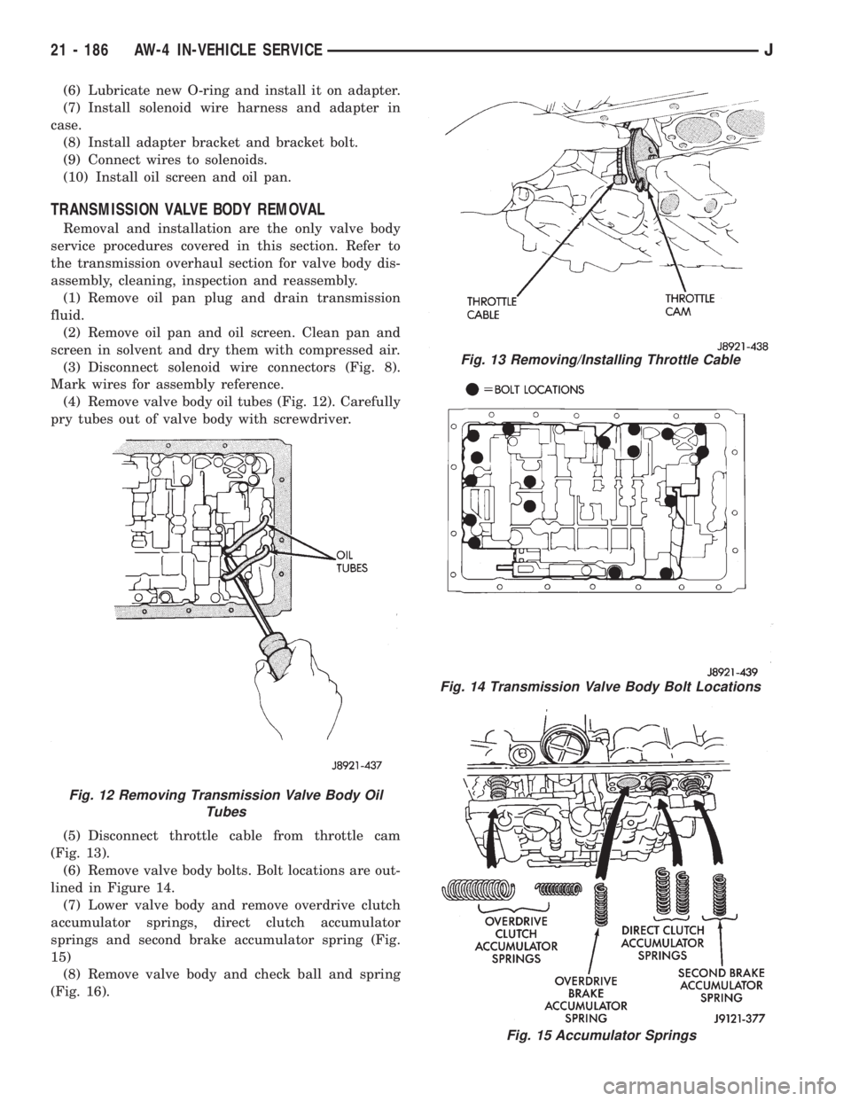
(3) Disconnect solenoid wire connectors (Fig. 8).
Mark wires for assembly reference.
(4) Remove valve body oil tubes (Fig. 12). Carefully
pry tubes out of valve body with screwdriver.
(5) Disconnect throttle cable from throttle cam
(Fig. 13).
(6) Remove valve body bolts. Bolt locations are out-
lined in Figure 14.
(7) Lower valve body and remove overdrive clutch
accumulator springs, direct clutch accumulator
springs and second brake accumulator spring (Fig.
15)
(8) Remove valve body and check ball and spring
(Fig. 16).
Fig. 13 Removing/Installing Throttle Cable
Fig. 14 Transmission Valve Body Bolt Locations
Fig. 15 Accumulator Springs
Fig. 12 Removing Transmission Valve Body Oil
Tubes
21 - 186 AW-4 IN-VEHICLE SERVICEJ
Page 1574 of 2198
the front bumper and radiator support be removed
for access to the cooler lines and attaching bracket.
REVERSE FLUSHING MAIN AND AUXILIARY
COOLERS AND COOLER LINES
Reverse flushing the cooler and lines will prevent
sludge and particles from flowing back into the
transmission after repair. The flushing procedure ap-
plies to standard (in-radiator) coolers and auxiliary
coolers equally.
Pressure equipment is preferred for reverse flush-
ing. However, reverse flushing can be performed us-
ing hand operated equipment as described in the
following procedure.
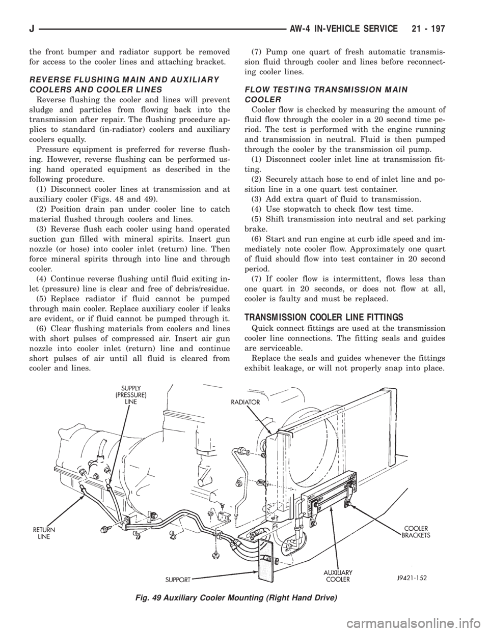
(1) Disconnect cooler lines at transmission and at
auxiliary cooler (Figs. 48 and 49).
(2) Position drain pan under cooler line to catch
material flushed through coolers and lines.
(3) Reverse flush each cooler using hand operated
suction gun filled with mineral spirits. Insert gun
nozzle (or hose) into cooler inlet (return) line. Then
force mineral spirits through into line and through
cooler.
(4) Continue reverse flushing until fluid exiting in-
let (pressure) line is clear and free of debris/residue.
(5) Replace radiator if fluid cannot be pumped
through main cooler. Replace auxiliary cooler if leaks
are evident, or if fluid cannot be pumped through it.
(6) Clear flushing materials from coolers and lines
with short pulses of compressed air. Insert air gun
nozzle into cooler inlet (return) line and continue
short pulses of air until all fluid is cleared from
cooler and lines.(7) Pump one quart of fresh automatic transmis-
sion fluid through cooler and lines before reconnect-
ing cooler lines.
FLOW TESTING TRANSMISSION MAIN
COOLER
Cooler flow is checked by measuring the amount of
fluid flow through the cooler in a 20 second time pe-
riod. The test is performed with the engine running
and transmission in neutral. Fluid is then pumped
through the cooler by the transmission oil pump.
(1) Disconnect cooler inlet line at transmission fit-
ting.
(2) Securely attach hose to end of inlet line and po-
sition line in a one quart test container.
(3) Add extra quart of fluid to transmission.
(4) Use stopwatch to check flow test time.
(5) Shift transmission into neutral and set parking
brake.
(6) Start and run engine at curb idle speed and im-
mediately note cooler flow. Approximately one quart
of fluid should flow into test container in 20 second
period.
(7) If cooler flow is intermittent, flows less than
one quart in 20 seconds, or does not flow at all,
cooler is faulty and must be replaced.
TRANSMISSION COOLER LINE FITTINGS
Quick connect fittings are used at the transmission
cooler line connections. The fitting seals and guides
are serviceable.
Replace the seals and guides whenever the fittings
exhibit leakage, or will not properly snap into place.
Fig. 49 Auxiliary Cooler Mounting (Right Hand Drive)
JAW-4 IN-VEHICLE SERVICE 21 - 197
Page 1576 of 2198
TORQUE CONVERTER STATOR CLUTCH
INSPECTION
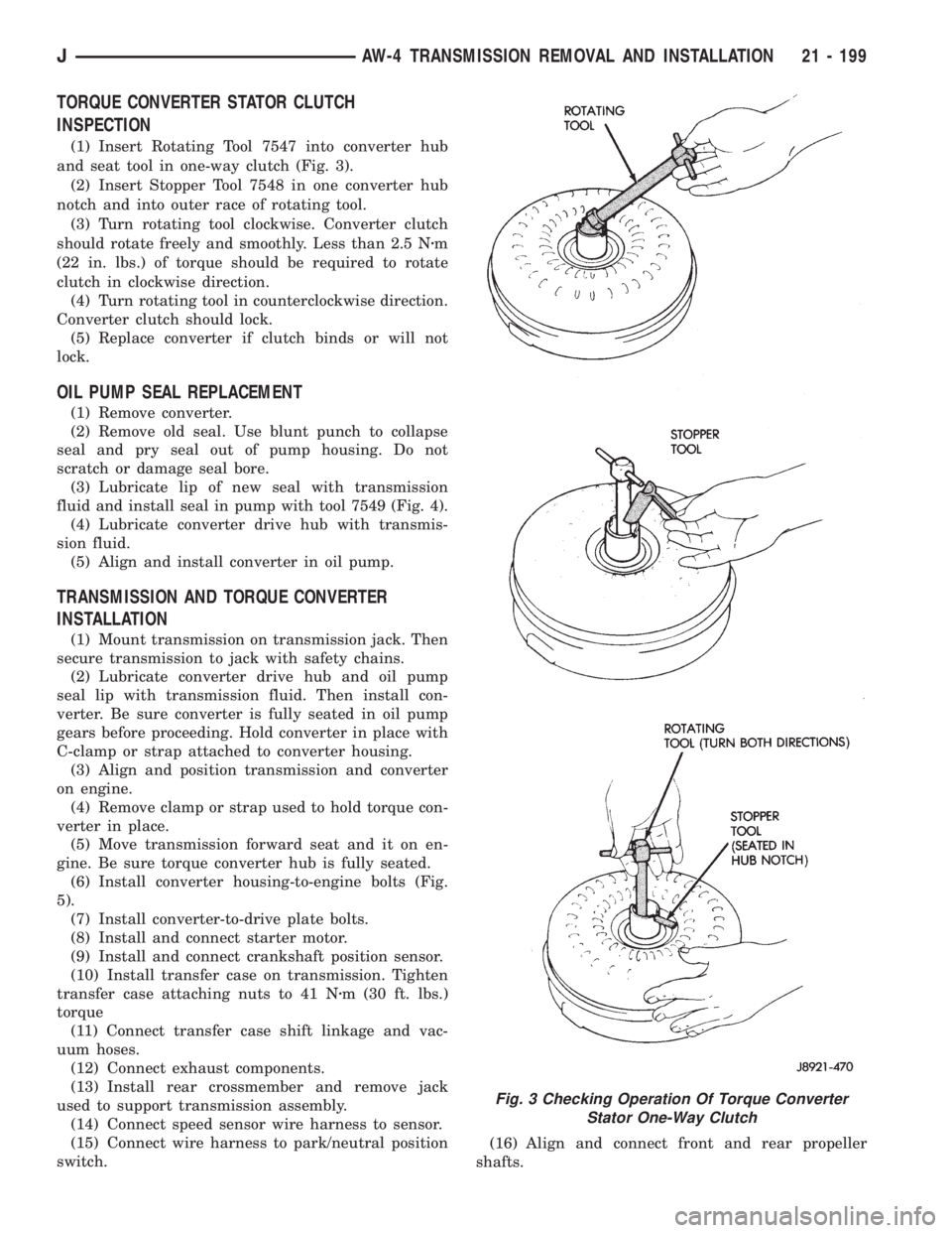
(1) Insert Rotating Tool 7547 into converter hub
and seat tool in one-way clutch (Fig. 3).
(2) Insert Stopper Tool 7548 in one converter hub
notch and into outer race of rotating tool.
(3) Turn rotating tool clockwise. Converter clutch
should rotate freely and smoothly. Less than 2.5 Nzm
(22 in. lbs.) of torque should be required to rotate
clutch in clockwise direction.
(4) Turn rotating tool in counterclockwise direction.
Converter clutch should lock.
(5) Replace converter if clutch binds or will not
lock.
OIL PUMP SEAL REPLACEMENT
(1) Remove converter.
(2) Remove old seal. Use blunt punch to collapse
seal and pry seal out of pump housing. Do not
scratch or damage seal bore.
(3) Lubricate lip of new seal with transmission
fluid and install seal in pump with tool 7549 (Fig. 4).
(4) Lubricate converter drive hub with transmis-
sion fluid.
(5) Align and install converter in oil pump.
TRANSMISSION AND TORQUE CONVERTER
INSTALLATION
(1) Mount transmission on transmission jack. Then
secure transmission to jack with safety chains.
(2) Lubricate converter drive hub and oil pump
seal lip with transmission fluid. Then install con-
verter. Be sure converter is fully seated in oil pump
gears before proceeding. Hold converter in place with
C-clamp or strap attached to converter housing.
(3) Align and position transmission and converter
on engine.
(4) Remove clamp or strap used to hold torque con-
verter in place.
(5) Move transmission forward seat and it on en-
gine. Be sure torque converter hub is fully seated.
(6) Install converter housing-to-engine bolts (Fig.
5).
(7) Install converter-to-drive plate bolts.
(8) Install and connect starter motor.
(9) Install and connect crankshaft position sensor.
(10) Install transfer case on transmission. Tighten
transfer case attaching nuts to 41 Nzm (30 ft. lbs.)
torque
(11) Connect transfer case shift linkage and vac-
uum hoses.
(12) Connect exhaust components.
(13) Install rear crossmember and remove jack
used to support transmission assembly.
(14) Connect speed sensor wire harness to sensor.
(15) Connect wire harness to park/neutral position
switch.(16) Align and connect front and rear propeller
shafts.
Fig. 3 Checking Operation Of Torque Converter
Stator One-Way Clutch
JAW-4 TRANSMISSION REMOVAL AND INSTALLATION 21 - 199
Page 1591 of 2198
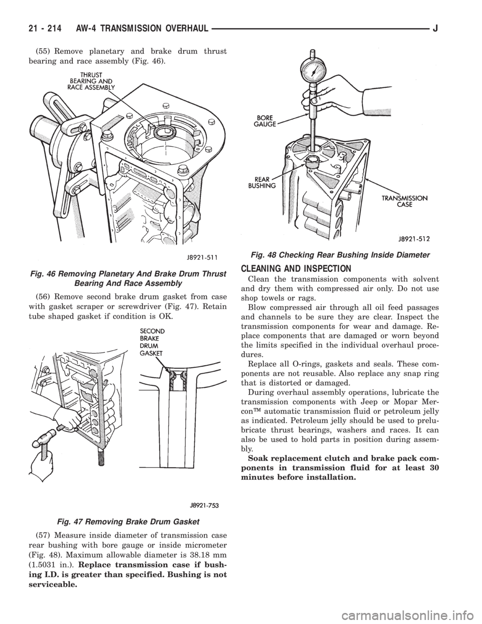
(55) Remove planetary and brake drum thrust
bearing and race assembly (Fig. 46).
(56) Remove second brake drum gasket from case
with gasket scraper or screwdriver (Fig. 47). Retain
tube shaped gasket if condition is OK.
(57) Measure inside diameter of transmission case
rear bushing with bore gauge or inside micrometer
(Fig. 48). Maximum allowable diameter is 38.18 mm
(1.5031 in.).Replace transmission case if bush-
ing I.D. is greater than specified. Bushing is not
serviceable.
CLEANING AND INSPECTION
Clean the transmission components with solvent
and dry them with compressed air only. Do not use
shop towels or rags.
Blow compressed air through all oil feed passages
and channels to be sure they are clear. Inspect the
transmission components for wear and damage. Re-
place components that are damaged or worn beyond
the limits specified in the individual overhaul proce-
dures.
Replace all O-rings, gaskets and seals. These com-
ponents are not reusable. Also replace any snap ring
that is distorted or damaged.
During overhaul assembly operations, lubricate the
transmission components with Jeep or Mopar Mer-
conŸ automatic transmission fluid or petroleum jelly
as indicated. Petroleum jelly should be used to prelu-
bricate thrust bearings, washers and races. It can
also be used to hold parts in position during assem-
bly.
Soak replacement clutch and brake pack com-
ponents in transmission fluid for at least 30
minutes before installation.Fig. 46 Removing Planetary And Brake Drum Thrust
Bearing And Race Assembly
Fig. 47 Removing Brake Drum Gasket
Fig. 48 Checking Rear Bushing Inside Diameter
21 - 214 AW-4 TRANSMISSION OVERHAULJ
Page 1631 of 2198
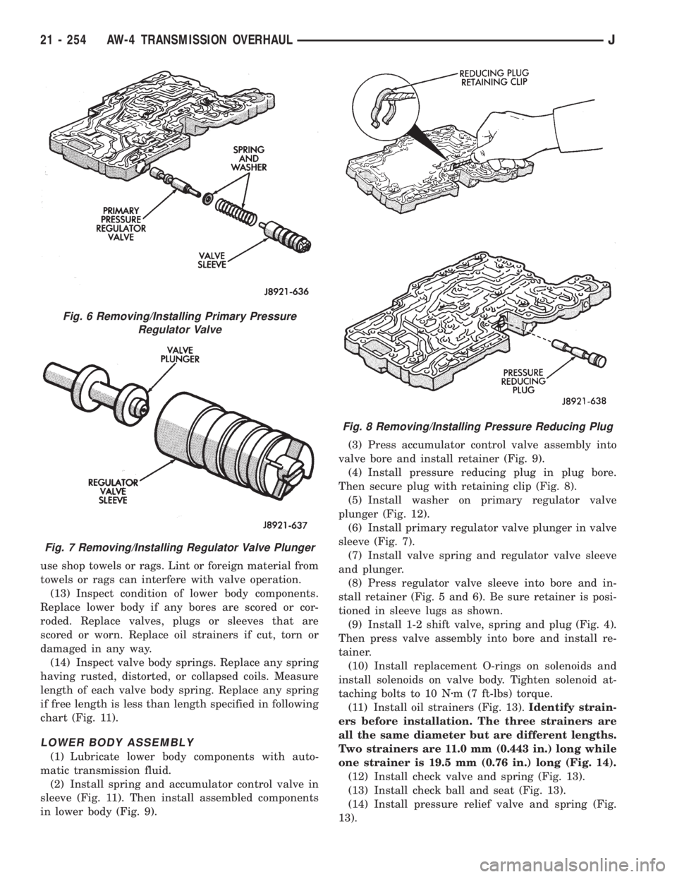
use shop towels or rags. Lint or foreign material from
towels or rags can interfere with valve operation.
(13) Inspect condition of lower body components.
Replace lower body if any bores are scored or cor-
roded. Replace valves, plugs or sleeves that are
scored or worn. Replace oil strainers if cut, torn or
damaged in any way.
(14) Inspect valve body springs. Replace any spring
having rusted, distorted, or collapsed coils. Measure
length of each valve body spring. Replace any spring
if free length is less than length specified in following
chart (Fig. 11).
LOWER BODY ASSEMBLY
(1) Lubricate lower body components with auto-
matic transmission fluid.
(2) Install spring and accumulator control valve in
sleeve (Fig. 11). Then install assembled components
in lower body (Fig. 9).(3) Press accumulator control valve assembly into
valve bore and install retainer (Fig. 9).
(4) Install pressure reducing plug in plug bore.
Then secure plug with retaining clip (Fig. 8).
(5) Install washer on primary regulator valve
plunger (Fig. 12).
(6) Install primary regulator valve plunger in valve
sleeve (Fig. 7).
(7) Install valve spring and regulator valve sleeve
and plunger.
(8) Press regulator valve sleeve into bore and in-
stall retainer (Fig. 5 and 6). Be sure retainer is posi-
tioned in sleeve lugs as shown.
(9) Install 1-2 shift valve, spring and plug (Fig. 4).
Then press valve assembly into bore and install re-
tainer.
(10) Install replacement O-rings on solenoids and
install solenoids on valve body. Tighten solenoid at-
taching bolts to 10 Nzm (7 ft-lbs) torque.
(11) Install oil strainers (Fig. 13).Identify strain-
ers before installation. The three strainers are
all the same diameter but are different lengths.
Two strainers are 11.0 mm (0.443 in.) long while
one strainer is 19.5 mm (0.76 in.) long (Fig. 14).
(12) Install check valve and spring (Fig. 13).
(13) Install check ball and seat (Fig. 13).
(14) Install pressure relief valve and spring (Fig.
13).
Fig. 6 Removing/Installing Primary Pressure
Regulator Valve
Fig. 7 Removing/Installing Regulator Valve Plunger
Fig. 8 Removing/Installing Pressure Reducing Plug
21 - 254 AW-4 TRANSMISSION OVERHAULJ
Page 1642 of 2198
TRANSMISSION ASSEMBLY AND ADJUSTMENT
(1) During assembly, lubricate components with
transmission fluid or petroleum jelly as indicated.
(2) If any of the transmission components are still
assembled after overhaul checking procedures, disas-
semble as necessary in preparation for transmission
assembly.
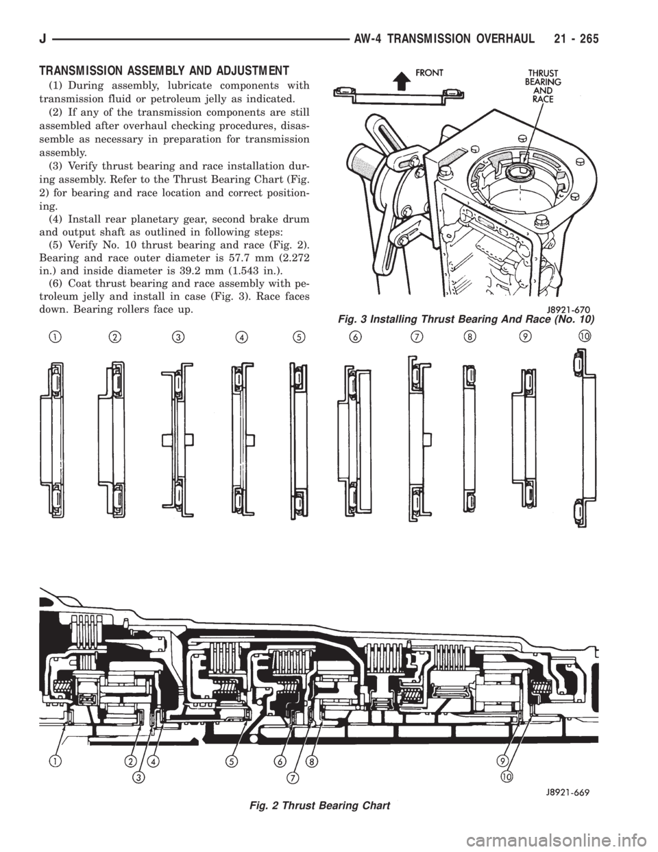
(3) Verify thrust bearing and race installation dur-
ing assembly. Refer to the Thrust Bearing Chart (Fig.
2) for bearing and race location and correct position-
ing.
(4) Install rear planetary gear, second brake drum
and output shaft as outlined in following steps:
(5) Verify No. 10 thrust bearing and race (Fig. 2).
Bearing and race outer diameter is 57.7 mm (2.272
in.) and inside diameter is 39.2 mm (1.543 in.).
(6) Coat thrust bearing and race assembly with pe-
troleum jelly and install in case (Fig. 3). Race faces
down. Bearing rollers face up.
Fig. 2 Thrust Bearing Chart
Fig. 3 Installing Thrust Bearing And Race (No. 10)
JAW-4 TRANSMISSION OVERHAUL 21 - 265
Page 1696 of 2198
Inspect the differential gears, thrust washers and
case halves. Replace the mainshaft gear if the gear
teeth or the brass ring on the underside of the gear
are damaged. Replace the differential as an assembly
if the gears, case halves, or the pins in the lower case
half are damaged.
Inspect the case halves, extension housing and re-
tainers for cracks, porosity, or damaged sealing sur-
faces. Inspect the shafts, gears, chain and shift
components for wear or damage.
Inspect all of the transfer case bearings for wear,
roughness, pitting, or galling. Replace worn or dam-
aged bearings as outlined in the assembly section.
TRANSFER CASE ASSEMBLY
(1) Lubricate transfer case components with auto-
matic transmission fluid or petroleum jelly (where in-
dicated) during assembly.
CAUTION: The bearing bores in various transfer
case components contain oil feed holes. Be sure re-
placement bearings do not block these feed holes.
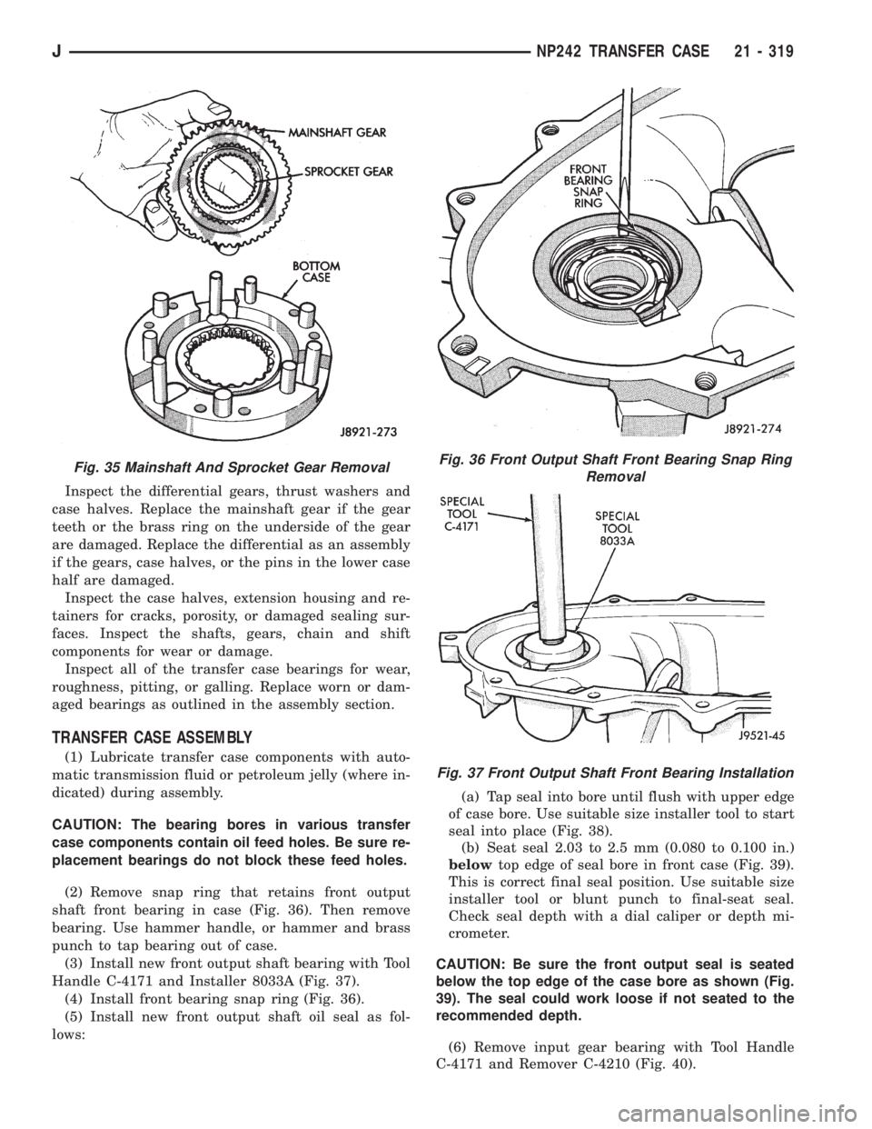
(2) Remove snap ring that retains front output
shaft front bearing in case (Fig. 36). Then remove
bearing. Use hammer handle, or hammer and brass
punch to tap bearing out of case.
(3) Install new front output shaft bearing with Tool
Handle C-4171 and Installer 8033A (Fig. 37).
(4) Install front bearing snap ring (Fig. 36).
(5) Install new front output shaft oil seal as fol-
lows:(a) Tap seal into bore until flush with upper edge
of case bore. Use suitable size installer tool to start
seal into place (Fig. 38).
(b) Seat seal 2.03 to 2.5 mm (0.080 to 0.100 in.)
belowtop edge of seal bore in front case (Fig. 39).
This is correct final seal position. Use suitable size
installer tool or blunt punch to final-seat seal.
Check seal depth with a dial caliper or depth mi-
crometer.
CAUTION: Be sure the front output seal is seated
below the top edge of the case bore as shown (Fig.
39). The seal could work loose if not seated to the
recommended depth.
(6) Remove input gear bearing with Tool Handle
C-4171 and Remover C-4210 (Fig. 40).
Fig. 35 Mainshaft And Sprocket Gear RemovalFig. 36 Front Output Shaft Front Bearing Snap Ring
Removal
Fig. 37 Front Output Shaft Front Bearing Installation
JNP242 TRANSFER CASE 21 - 319
Page 1964 of 2198
BELT TENSIONERÐXJ MODELS WITH
RIGHT HAND DRIVE, AUTOMATIC........7-42
BELT TENSIONÐEXCEPT RIGHT HAND
DRIVE (RHD).........................7-38
BELT TENSIONÐEXCEPT RIGHT HAND
DRIVE (RHD) MODELS.................7-45
BELT TENSIONÐRIGHT HAND DRIVE
(RHD)..............................7-38
BELT/BUCKLEÐXJ, FRONT SHOULDER . . . 23-90
BELT/BUCKLEÐXJ, REAR SHOULDER/
LAP ...............................23-91
BELTLINE SEALÐYJ.................23-142
BELTS, ENGINE ACCESSORY DRIVE.......7-38
BELTSÐYJ, FRONT SHOULDER........23-154
BELTSÐYJ, REAR SHOULDER.........23-154
BENCH BLEEDING, MASTER CYLINDER....5-21
BENCH, GEAR ADJUSTMENTS ON.......19-44
BENCH SEATÐYJ, REAR..............23-153
BEZELÐXJ, INSTRUMENT CLUSTER.....23-80
BEZELÐYJ, INSTRUMENT CLUSTER....23-151
BIN REMOVE/INSTALL, SUNGLASSES
STORAGE...........................8C-7
BLADE REMOVE/INSTALL, WINDSHIELD
WIPER.............................8K-17
BLEEDING, MASTER CYLINDER BENCH....5-21
BLEEDING RECOMMENDATIONS, BRAKE . . . 5-10
BLEEDING (WITH ABS BRAKES), BRAKE . . . 5-11
BLEEDING (WITH STANDARD BRAKES),
BRAKE..............................5-11
BLEEDINGÐBRAKELINES AND HOSES,
BRAKE FLUIDÐBRAKE.................5-10
BLOCK, CYLINDER................9-49,9-91
BLOCK HEATER, ENGINE................7-44
BLOCKSÐTWO-DOOR VEHICLES, FRONT
DOOR SPACER......................23-53
BLOWER MOTOR; AIR CONDITIONING/
HEATER (XJ)......................8W-42-1
BLOWER MOTOR; AIR CONDITIONING/
HEATER (XJ-RHD)..................8W-42-1
BLOWER MOTOR; HEATING AND AIR
CONDITIONING......................24-17
BLOWER MOTOR, A/C.................24-35
BLOWER MOTOR, A/C-HEATER; AIR
CONDITIONING/HEATER (YJ).........8W-42-2
BLOWER MOTOR (HEATING)...........24-33
BLOWER MOTOR RESISTORS
REPLACEMENT......................24-31
BLOWER MOTOR SWITCH.............24-16
BLOWER MOTOR/AIR DOOR MOTOR
SWITCH REPLACEMENT...............24-32
BLOWER MOTOR/FAN REPLACEMENT....24-24
BODY ASSEMBLY AND ADJUSTMENT,
VALVE ............................21-153
BODY CHECK BALL DIMENSIONS, AW-4
VALVE ............................21-341
BODY CODE LETTERS, JEEP..............5-2
BODY LUBRICANT SPECIFICATIONS.......0-33
BODY OVERHAUL, TRANSMISSION
VALVE ............................21-250
BODY REMOVAL, TRANSMISSION VALVE . 21-186
BODY REMOVAL, VALVE..............21-104
BODY SERVICE INFORMATION, GENERAL . . 23-1
BODY SERVICE, VALVE...............21-104
BODY SIDE MOLDING/CLADDINGÐXJ....23-20
BODY SIDE STEP MOLDINGÐYJ.......23-115
BODY SOLENOIDS, TRANSMISSION
VALVE ............................21-184
BODY STRIPES/DECALSÐXJ...........23-21
BODY STRIPES/DECALSÐYJ..........23-116
BODY, THROTTLE...............14-33,14-64
BOLT IDENTIFICATION..............Intro.-14
BOLT STRENGTH..................Intro.-15
BOOSTER CHECK VALVE TEST, POWER.....5-9
BOOSTER INSTALLATION (XJ WITH
ABS), POWER BRAKE..................5-27
BOOSTER INSTALLATION (XJ WITHOUT
ABS), POWER BRAKE..................5-30
BOOSTER INSTALLATION (YJ), POWER
BRAKE..............................5-30
BOOSTER, MASTER CYLINDER/POWER
BRAKE
..............................5-34
BOOSTER OPERATION, POWER BRAKE
....5-23
BOOSTER REMOVAL (XJ WITH ABS),
POWER BRAKE
.......................5-24
BOOSTER REMOVAL (XJ WITHOUT ABS),
POWER BRAKE
.......................5-29
BOOSTER REMOVAL (YJ), POWER
BRAKE
..............................5-30BOOSTER TEST, MASTER CYLINDER/
POWER..............................5-8
BOOSTER VACUUM TEST, POWER.........5-9
BOOSTERÐBRAKE PEDALÐ
BRAKELIGHT SWITCH, POWER BRAKE....5-22
BORES, HONING CYLINDER..............9-2
BOX LAMP, GLOVE; INTERIOR LIGHTING
(XJ).............................8W-44-1
BOX LAMP, GLOVE; INTERIOR LIGHTING
(XJ-RHD).........................8W-44-1
BOXÐYJ, GLOVE...................23-152
BRACKET REPLACEMENTÐXJ, INTERIOR
REARVIEW MIRROR SUPPORT..........23-68
BRACKETÐYJ, REARVIEW MIRROR
RETAINING........................23-144
BRACKETSÐXJ, SPARE TIRE/WHEEL
HOLDDOWN AND FLOOR..............23-98
BRAKE ADJUSTMENT, DRUM............5-57
BRAKE BLEEDING RECOMMENDATIONS....5-10
BRAKE BLEEDING (WITH ABS BRAKES)....5-11
BRAKE BLEEDING (WITH STANDARD
BRAKES)............................5-11
BRAKE BOOSTER INSTALLATION (XJ
WITH ABS), POWER...................5-27
BRAKE BOOSTER INSTALLATION (XJ
WITHOUT ABS), POWER................5-30
BRAKE BOOSTER INSTALLATION (YJ),
POWER.............................5-30
BRAKE BOOSTER, MASTER CYLINDER/
POWER.............................5-34
BRAKE BOOSTER OPERATION, POWER....5-23
BRAKE BOOSTER REMOVAL (XJ WITH
ABS), POWER........................5-24
BRAKE BOOSTER REMOVAL (XJ
WITHOUT ABS), POWER................5-29
BRAKE BOOSTER REMOVAL (YJ),
POWER.............................5-30
BRAKE BOOSTERÐBRAKE PEDALÐ
BRAKELIGHT SWITCH, POWER...........5-22
BRAKE CABLE TENSIONER ADJUSTMENT
(XJ/YJ), PARKING.....................5-69
BRAKE CABLE TENSIONER
REPLACEMENT (XJ), PARKING...........5-66
BRAKE CHECK, PRELIMINARY............5-4
BRAKE COMPONENTS...................5-1
BRAKE DIAGNOSIS, ABS.................5-3
BRAKE DIAGNOSIS, SERVICE.............5-4
BRAKE DRUM REFINISHING.............5-58
BRAKE FLUID CONTAMINATION.......5-10,5-7
BRAKE FLUID LEVEL...................5-10
BRAKE FLUID, RECOMMENDED..........5-10
BRAKE FLUID/LUBRICANTS/CLEANING
SOLVENTS............................5-2
BRAKE FLUIDÐBRAKE BLEEDINGÐ
BRAKELINES AND HOSES...............5-10
BRAKE FRONT CABLE REPLACEMENT
(YJ), PARKING........................5-67
BRAKE HANDLE COVERÐXJ, PARKING . . . 23-94
BRAKE LEVER INSTALLATION (XJ WITH
FULL CONSOLE), PARKING..............5-64
BRAKE LEVER INSTALLATION (XJ WITH
MINI CONSOLE), PARKING..............5-63
BRAKE LEVER INSTALLATION (XJ
WITHOUT CONSOLE), PARKING..........5-65
BRAKE LEVER REMOVAL (XJ WITH FULL
CONSOLE), PARKING..................5-63
BRAKE LEVER REMOVAL (XJ WITH MINI
CONSOLE), PARKING..................5-62
BRAKE LEVER REMOVAL (XJ WITHOUT
CONSOLE), PARKING
..................5-64
BRAKE MALFUNCTIONS, DIAGNOSING
PARKING
.............................5-8
BRAKE NOISE
.........................5-7
BRAKE OPERATION, PARKING
...........5-60
BRAKE OVERHAUL, SECOND
..........21-241
BRAKE PACK REQUIREMENTS, AW-4
CLUTCH
...........................21-341
BRAKE PEDAL BUSHINGS, CLUTCH
.......0-22
BRAKE PEDAL INSTALLATION
............5-31
BRAKE PEDAL INSTALLATION (YJ),
PARKING
............................5-66
BRAKE PEDAL REMOVAL
...............5-31
BRAKE PEDAL REMOVAL (YJ), PARKING
. . . 5-66
BRAKE PEDAL TRAVEL SENSOR;
ANTI-LOCK BRAKES (YJ)
............8W-32-1
BRAKE PISTON AND TRANSMISSION
CASE OVERHAUL, FIRST-REVERSE
......21-247BRAKE REAR CABLE REPLACEMENT
(XJ), PARKING........................5-67
BRAKE REAR CABLE REPLACEMENT
(YJ), PARKING........................5-68
BRAKE ROTOR REFINISHING, DISC.......5-53
BRAKE ROTOR RUNOUT, DISC...........5-52
BRAKE ROTOR THICKNESS, DISC........5-52
BRAKE SAFETY PRECAUTIONS............5-2
BRAKE SWITCH......................14-59
BRAKE SWITCH INPUT; ANTI-LOCK
BRAKES (XJ)......................8W-32-2
BRAKE SWITCH INPUT; ANTI-LOCK
BRAKES (XJ-RHD).................8W-32-2
BRAKE SWITCH INPUT; ANTI-LOCK
BRAKES (YJ)......................8W-32-2
BRAKE SWITCH INPUT; FUEL/IGNITION
(XJ).............................8W-30-5
BRAKE SWITCH INPUT; FUEL/IGNITION
(YJ).............................8W-30-5
BRAKE SWITCH INPUT; FUEL/IGNITION
(XJ-RHD).........................8W-30-5
BRAKE SWITCH, PARKING..............5-68
BRAKE SWITCHÐPCM INPUT..........14-22
BRAKE SYSTEM, POWER...............0-30
BRAKE TORQUE SPECIFICATIONS.........5-70
BRAKE WARNING LAMP; INSTRUMENT
CLUSTER (XJ).....................8W-40-2
BRAKE WARNING LAMP; INSTRUMENT
CLUSTER (XJ-RHD)................8W-40-2
BRAKE WARNING LAMP; INSTRUMENT
CLUSTER (YJ)......................8W-40-2
BRAKE WARNING LIGHTS................5-1
BRAKELIGHT SWITCH ADJUSTMENT......5-32
BRAKELIGHT SWITCH INSTALLATION......5-32
BRAKELIGHT SWITCH REMOVAL.........5-32
BRAKELINE CHARTS...................5-12
BRAKELINES AND HOSES...............5-12
BRAKELINING, CONTAMINATED...........5-7
BRAKELINING MATERIAL................5-1
BRAKES (ABS), ANTILOCK...............5-1
BRAKES, DISC........................5-45
BRAKES DO NOT HOLD AFTER DRIVING
THROUGH DEEP WATER PUDDLES........5-7
BRAKES, DRUM......................5-55
BRAKES, PARKING....................5-60
BRAKESHOE INSTALLATION, DISC........5-47
BRAKESHOE INSTALLATION, DRUM.......5-55
BRAKESHOE REMOVAL, DISC............5-46
BRAKESHOE REMOVAL, DRUM...........5-55
BRAKING MODE, ABS OPERATION IN
ANTILOCK...........................5-36
BRAKING MODE, ABS OPERATION IN
NORMAL............................5-35
BREAK-IN, ENGINE....................0-15
BRUSH GUARDÐXJ...................23-3
BUCKET SEAT CUSHION AND COVERÐ
XJ ................................23-81
BUCKET SEAT PLATFORMÐXJ..........23-82
BUCKET SEATBACK COVER AND
FRAMEÐXJ.........................23-81
BUCKET SEATSÐXJ, FRONT............23-81
BUCKET SEATSÐYJ.................23-153
BULB APPLICATIONÐXJ VEHICLES......8L-18
BULB APPLICATIONÐYJ VEHICLES......8L-32
BULB REMOVE/INSTALL, READING/
COURTESY LAMP.....................8C-8
BULB REPLACEMENTÐXJ, BACK-UP/
REAR TURN SIGNAL/TAIL LAMP.........8L-12
BULB REPLACEMENTÐXJ, FRONT
PARK/TURN SIGNAL LAMP..............8L-9
BULB REPLACEMENTÐXJ, HEADLAMP....8L-7
BULB REPLACEMENTÐXJ, SIDE
MARKER LAMP......................8L-10
BULB REPLACEMENTÐXJ, UNDERHOOD
LAMP..............................8L-13
BULB REPLACEMENTÐYJ, BACK-UP/
REAR TURN SIGNAL/TAIL LAMP.........8L-28
BULB REPLACEMENTÐYJ, FRONT
PARK/TURN SIGNAL LAMP.............8L-25
BULB REPLACEMENTÐYJ, HEADLAMP . . . 8L-23
BULB REPLACEMENTÐYJ, SIDE
MARKER LAMP
......................8L-25
BULB REPLACEMENTÐYJ, UNDERHOOD
LAMP
..............................8L-29
BULB REPLACEMENTÐYJ VEHICLES,
HARDTOP DOME/CARGO LAMP
.........8L-31
BUMPER, FRONT
.................13-16,13-5
BUMPER, REAR
..................13-16,13-8
JINDEX 3
Description Group-Page Description Group-Page Description Group-Page