1995 JEEP CHEROKEE warning light
[x] Cancel search: warning lightPage 633 of 2198
READING LAMPS
Circuit M1 from the IOD fuse (fuse F9) in the fuse
block supplies power to the reading lamps. Circuit
M1 is HOT at all times. When the operator depresses
the reading lamp, the reading lamp switch closes and
supplies ground on circuit Z1.
VISOR VANITY MIRROR LAMPS
Circuit M1 from the IOD fuse (fuse F9) in the fuse
block supplies power to the vanity lamps. Circuit M1
is HOT at all times. When the vanity lamps switch
closes, voltage flows to vanity mirror lamps. The van-
ity mirror is case grounded.
UNDERHOOD LAMP
Circuit A6 from fuse 16 in the Power Distribution
Center (PDC) supplies battery voltage for the under-
hood lamp. A mercury switch, in series after the
lamp, connects the lamp to ground on circuit Z1.
When the hood is raised, mercury inside the switch
moves to a position where it connects circuit M1 to
ground circuit Z1, illuminating the lamp.
CHIME/BUZZER MODULE
The buzzer or optional chime module sounds an au-
dible warning tone. The tone sounds for seat belt
warning and when the ignition key is in the ignition
switch while the drivers door is open. The tone also
sounds when the ignition key is in the ON position
while the drivers side seat belt is not buckled. Lastly,
the tone sounds when the headlamps are ON when
the ignition is OFF. Refer to Group 8U for system op-
eration.
When the ignition switch is in the RUN or START
position, circuit F87 from fuse 17 in the fuse block
supplies power to the chime/buzzer module. Circuit
A21 from the ignition switch supplies power to fuse
17.
Circuit L7 from fuse 15 in the fuse block also sup-
plies power to the chime/buzzer module. Circuit A3
from fuse 5 in the Power Distribution Center (PDC)
powers fuse 15.
When the parking lamps or headlamps are ON, the
headlamp switch connects circuit G26 with the driv-
ers side door jamb switch. Circuit G26 also connects
to the key-in switch. Circuit M11 connects the key-in
switch to the chime/buzzer module and the headlamp
switch.
If the headlamps are ON, and the drivers door
opens, ground for the chime/buzzer is on circuit C26
from the headlamp switch through the door jamb
switch to circuit Z1.
If the headlamps are OFF with the key in the ig-
nition while the drivers side door is open, ground forthe chime/buzzer is supplied through the key-in
switch. The ground path is over circuit M11, through
the closed key-in switch to circuit C26. From circuit
C26, the ground path continues through the drivers
door jamb switch to circuit Z1.
Circuit G11 from the buzzer powers the seat belt
warning lamp in the instrument cluster. Circuit Z1
at the instrument cluster provides ground for the
lamp.
Circuit G10 from the buzzer connects to the seat
belt switch. When the seat belt switch closes a path
to ground is completed on circuit Z1 and the tone
sounds momentarily.
Circuit Z1 also grounds the chime\buzzer module.
HELPFUL INFORMATION
Circuit F87 also powers the instrument cluster and
the headlamp delay module.
DIAGRAM INDEX
Component Page
Cargo Lamp............................8W-44-6
Chime/Buzzer Module......................8W-44-3
Courtesy Lamps.........................8W-44-5
Dome Lamp............................8W-44-7
Door Jamb Switches.....................8W-44-10
Fuse 3 (PDC).........................8W-44-4, 6
Fuse 5 (PDC).........................8W-44-3, 8
Fuse 6 (PDC)...........................8W-44-3
Fuse 9 (Fuse Block).....................8W-44-4, 6
Fuse 15 (Fuse Block)....................8W-44-3, 8
Fuse 16 (PDC)........................8W-44-4, 6
Fuse 17 (Fuse Block)......................8W-44-3
Fuse 19 (Fuse Block)......................8W-44-8
Glove Box Lamp and Switch.................8W-44-5
Headlamp Switch...................8W-44-3, 4, 5, 8
Headlamp Delay Module....................8W-44-4
Headlamp Delay Relay.....................8W-44-3
Ignition Switch..........................8W-44-3
Instrument Cluster........................8W-44-3
Instrument Panel Illumination Lamps..........8W-44-8, 9
Intermittent Wiper Control Module.............8W-44-4
Key-In Switch...........................8W-44-4
Liftgate Switch..........................8W-44-6
Reading Lamps..........................8W-44-7
Remote Keyless Entry Module................8W-44-7
Seat Belt Switch.........................8W-44-3
Telltale Connector (Instrument Cluster)...........8W-44-3
Time Delay Relay........................8W-44-4
Underhood Lamp.........................8W-44-4
Vanity Lamps...........................8W-44-7
8W - 44 - 2 8W-44 INTERIOR LIGHTINGÐXJ VEHICLESJ
Page 814 of 2198
WIRING DIAGRAMS
CONTENTS
page page
8W-01 GENERAL INFORMATIONÐWIRING
DIAGRAMS...................... 8W-01-1
8W-10 FUSE/FUSE BLOCK........... 8W-10-1
8W-11 POWER DISTRIBUTION........ 8W-11-1
8W-15 GROUND DISTRIBUTION....... 8W-15-1
8W-20 CHARGING SYSTEM.......... 8W-20-1
8W-21 STARTING SYSTEM........... 8W-21-1
8W-30 FUEL/IGNITION.............. 8W-30-1
8W-31 TRANSMISSION CONTROLS.... 8W-31-1
8W-32 ANTI-LOCK BRAKES........... 8W-32-1
8W-33 VEHICLE SPEED CONTROL..... 8W-33-1
8W-40 INSTRUMENT CLUSTER....... 8W-40-1
8W-41 HORN/CIGAR LIGHTER........ 8W-41-1
8W-42 AIR CONDITIONING/HEATER.... 8W-42-1
8W-44 INTERIOR LIGHTING.......... 8W-44-1
8W-47 AUDIO SYSTEM.............. 8W-47-18W-48 HEATED REAR WINDOW....... 8W-48-1
8W-49 OVERHEAD CONSOLE.......... 8W-49-1
8W-50 FRONT LIGHTING............ 8W-50-1
8W-51 REAR LIGHTING............. 8W-51-1
8W-52 TURN SIGNALS.............. 8W-52-1
8W-53 WIPERS.................... 8W-53-1
8W-54 TRAILER TOW................ 8W-54-1
8W-60 POWER WINDOWS............ 8W-60-1
8W-61 POWER DOOR LOCKS......... 8W-61-1
8W-62 POWER MIRRORS............ 8W-62-1
8W-63 POWER SEAT................ 8W-63-1
8W-70 SPLICE INFORMATION........ 8W-70-1
8W-80 CONNECTOR PIN OUTS....... 8W-80-1
8W-90 CONNECTOR LOCATIONS...... 8W-90-1
8W-95 SPLICE LOCATIONS........... 8W-95-1
HOW TO USE THIS GROUP
The purpose of this group is to show the electrical
circuits in a clear, simple fashion and to make trou-
bleshooting easier. Components that work together
are shown together. All electrical components used in
a specific system are shown on one diagram. The feed
for a system is shown at the top of the page. All
wires, connectors, splices, and components are shown
in the flow of current to the bottom of the page. Wir-
ing which is not part of the circuit represented is ref-
erenced to another page/section, where the complete
circuit is shown. In addition, all switches, compo-
nents, and modules are shown in theat rest posi-
tion with the doors closed and the key removed
from the ignition.
If a component is part of several different circuits,
it is shown in the diagram for each. For example, the
headlamp switch is the main part of the exterior
lighting, but it also affects the interior lighting and
the chime warning system.
It is important to realize that no attempt is
made on the diagrams to represent components
and wiring as they appear on the vehicle. For
example, a short piece of wire is treated the
same as a long one. In addition, switches and
other components are shown as simply as pos-
sible, with regard to function only.
The wiring diagram show circuits for all wheel-
bases. If there is a difference in systems or compo-
nents between wheel-bases, an identifier is placed
next to the component.
SECTION IDENTIFICATION
Sections in Group 8W are organized by sub-sys-
tems. The sections contain circuit operation descrip-
tions, helpful information, and system diagrams. The
intention is to organize information by system, con-
sistently from year to year.
CONNECTOR LOCATIONS
Section 8W-90 contains Connector Location illus-
trations. The illustrations contain the connector
number and component identification. Connector Lo-
cation charts in Section 8W-90 reference the illustra-
tion number for components and connectors.
Section 8W-80 shows each connector and the cir-
cuits involved with that connector. The connectors
are identified using the number on the Diagram
pages.
SPLICE LOCATIONS
Splice Location charts in Section 8W-70 show the
entire splice, and provide references to other sections
the splice serves.
Section 8W-95 contains illustrations that show the
general location of the splices in each harness. The
illustrations show the splice by number, and provide
a written location.
JWIRING DIAGRAMSÐXJ-RHD 8W - 1 - 1
Page 909 of 2198
CHIME/BUZZER MODULE
The buzzer or optional chime module sounds an au-
dible warning tone. The tone sounds for seat belt
warning and when the ignition key is in the ignition
switch while the drivers door is open. The tone also
sounds when the ignition key is in the ON position
while the drivers side seat belt is not buckled. Lastly,
the tone sounds when the headlamps are ON when
the ignition is OFF. Refer to Group 8U for system op-
eration.
When the ignition switch is in the RUN or START
position, fuse F87 from fuse 26 in the fuse block sup-
plies power to the chime/buzzer module. Circuit A21
from the ignition switch supplies power to fuse 26.
Circuit L7 from fuse 9 in the fuse block also sup-
plies power to the chime/buzzer module. Circuit A3
from fuse 5 in the Power Distribution Center (PDC)
powers fuse 9.
When the parking lamps or headlamps are ON, the
headlamp switch connects circuit G26 with the driv-
ers side door jamb switch. Circuit G26 also connects
to the key-in switch. Circuit M11 connects the key-in
switch to the chime module and the headlamp
switch.
If the headlamps are ON, and the drivers door
opens, ground for the chime/buzzer is on circuit C26
from the headlamp switch through the door jamb
switch to circuit Z1.
If the headlamps are OFF with the key in the ig-
nition while the drivers side door is open, ground for
the chime/buzzer is supplied through the key-in
switch. The ground path is over circuit M11, through
the closed key-in switch to circuit C26. From circuit
C26, the ground path continues through the drivers
door jamb switch to circuit Z1.
Circuit G11 from the buzzer powers the seat belt
warning lamp in the instrument cluster. Circuit Z1
at the instrument cluster provides ground for the
lamp.Circuit G10 from the buzzer connects to the seat
belt switch. When the seat belt switch closes a path
to ground is completed on circuit Z1 and the tone
sounds momentarily.
Circuit Z1 also grounds the chime buzzer module.
HELPFUL INFORMATION
Circuit F87 also powers the instrument cluster and
the headlamp delay module.
DIAGRAM INDEX
Component Page
Cargo Lamp............................8W-44-6
Chime/Buzzer Module......................8W-44-3
Courtesy Lamps.........................8W-44-5
Dome Lamp............................8W-44-6
Door Jamb Switches......................8W-44-7
Fuse 3 (PDC)...........................8W-44-6
Fuse 5 (PDC).........................8W-44-5, 8
Fuse 6 (PDC)...........................8W-44-6
Fuse 9 (Fuse Block).....................8W-44-3, 8
Fuse 16 (PDC)........................8W-44-4, 6
Fuse 25 (Fuse Block)......................8W-44-8
Fuse 26 (Fuse Block)......................8W-44-3
Glove Box Lamp and Switch.................8W-44-5
Headlamp Switch....................8W-44-3, thru 8
Headlamp Delay Module....................8W-44-3
Ignition Switch..........................8W-44-3
Instrument Cluster......................8W-44-3, 9
Instrument Panel Illumination Lamps..........8W-44-8, 9
Key-In Switch...........................8W-44-4
Liftgate Switch..........................8W-44-6
Reading Lamps..........................8W-44-6
Seat Belt Switch.........................8W-44-3
Telltale Connector (Instrument Cluster)...........8W-44-3
Time Delay Relay........................8W-44-4
Underhood Lamp.........................8W-44-4
8W - 44 - 2 8W-44 INTERIOR LIGHTINGÐXJ-RHDJ
Page 1097 of 2198
CYLINDER COMBUSTION PRESSURE LEAKAGE
TEST
The combustion pressure leakage test provides an
accurate means for determining engine condition.
Combustion pressure leakage testing will detect:
²Exhaust and intake valve leaks (improper seat-
ing).
²Leaks between adjacent cylinders or into water
jacket.
²Any causes for combustion/compression pressure
loss.
WARNING: DO NOT REMOVE THE RADIATOR CAP
WITH THE SYSTEM HOT AND UNDER PRESSURE
BECAUSE SERIOUS BURNS FROM COOLANT CAN
OCCUR.
Check the coolant level and fill as required. DO
NOT install the radiator cap.
Start and operate the engine until it attains nor-
mal operating temperature, then turn the engine
OFF.
Remove the spark plugs.
Remove the oil filler cap.
Remove the air cleaner.
Calibrate the tester according to the manufactur-
er's instructions. The shop air source for testing
should maintain 483 kPa (70 psi) minimum, 1 379
kPa (200 psi) maximum and 552 kPa (80 psi) recom-
mended.
Perform the test procedures on each cylinder ac-
cording to the tester manufacturer's instructions.
While testing, listen for pressurized air escaping
through the throttle body, tailpipe and oil filler cap
opening. Check for bubbles in the radiator coolant.
All gauge pressure indications should be equal,
with no more than 25% leakage.
FOR EXAMPLE:At 552 kPa (80 psi) input pres-
sure, a minimum of 414 kPa (60 psi) should be main-
tained in the cylinder.
Refer to the Cylinder Combustion Pressure Leak-
age Test Diagnosis chart.
INSPECTION (ENGINE OIL LEAKS IN GENERAL)
Begin with a through visual inspection of the en-
gine, particularly at the area of the suspected leak. If
an oil leak source is not readily identifiable, the fol-
lowing steps should be followed:
(1) Do not clean or degrease the engine at this
time because some solvents may cause rubber to
swell, temporarily stopping the leak.
(2) Add an oil soluble dye (use as recommended by
manufacturer). Start the engine and let idle for ap-
proximately 15 minutes. Check the oil dipstick to
make sure the dye is thoroughly mixed as indicated
with a bright yellow color under a black light.(3) Using a black light, inspect the entire engine
for fluorescent dye, particularly at the suspected area
of oil leak. If the oil leak is found and identified, re-
pair per service manual instructions.
(4) If dye is not observed, drive the vehicle at var-
ious speeds for approximately 24km (15 miles), and
repeat step (3).
If the oil leak source is not positively identi-
fied at this time, proceed with the air leak detec-
tion test method as follows:
(1) Disconnect the breather cap to air cleaner hose
at the breather cap end. Cap or plug breather cap
nipple.
(2) Remove the PCV valve from the cylinder head
cover. Cap or plug the PCV valve grommet.
(3) Attach an air hose with pressure gauge and
regulator to the dipstick tube.
CAUTION: Do not subject the engine assembly to
more than 20.6 kpa (3 PSI) of test pressure.
(4) Gradually apply air pressure from 1 psi to 2.5
psi maximum while applying soapy water at the sus-
pected source. Adjust the regulator to the suitable
test pressure that provide the best bubbles which
will pinpoint the leak source. If the oil leak is de-
tected and identified, repair per service manual pro-
cedures.
(5) If the leakage occurs at the rear oil seal area,
refer to the section, Inspection for Rear Seal Area
Leak.
(6) If no leaks are detected, turn off the air supply
and remove the air hose and all plugs and caps. In-
stall the PCV valve and breather cap hose. Proceed
to step 7.
(7) Clean the oil off the suspect oil leak area using
a suitable solvent. Drive the vehicle at various
speeds approximately 24 km (15 miles). Inspect the
engine for signs of an oil leak by using a black light.
INSPECTION FOR REAR SEAL AREA LEAKS
Since it is sometimes difficult to determine the
source of an oil leak in the rear seal area of the en-
gine, a more involved inspection is necessary. The fol-
lowing steps should be followed to help pinpoint the
source of the leak.
If the leakage occurs at the crankshaft rear oil seal
area:
(1) Disconnect the battery.
(2) Raise the vehicle.
(3) Remove torque converter or clutch housing
cover and inspect rear of block for evidence of oil.
Use a black light to check for the oil leak:
(a) Circular spray pattern generally indicates
seal leakage or crankshaft damage.
(b) Where leakage tends to run straight down,
possible causes are a porous block, distributor seal,
camshaft bore cup plugs oil galley pipe plugs, oil
9 - 6 ENGINESJ
Page 1230 of 2198
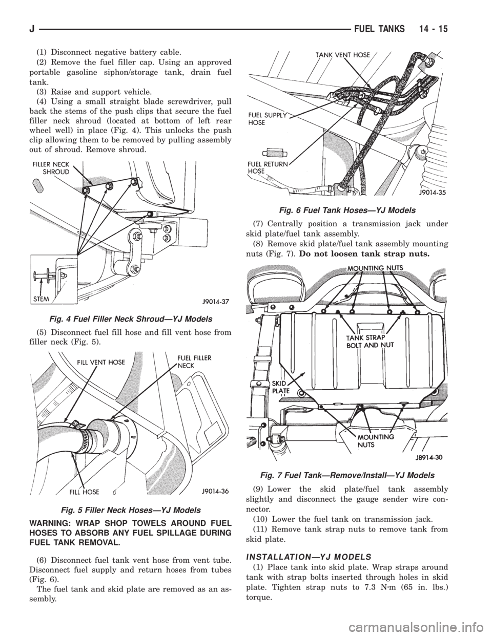
(1) Disconnect negative battery cable.
(2) Remove the fuel filler cap. Using an approved
portable gasoline siphon/storage tank, drain fuel
tank.
(3) Raise and support vehicle.
(4) Using a small straight blade screwdriver, pull
back the stems of the push clips that secure the fuel
filler neck shroud (located at bottom of left rear
wheel well) in place (Fig. 4). This unlocks the push
clip allowing them to be removed by pulling assembly
out of shroud. Remove shroud.
(5) Disconnect fuel fill hose and fill vent hose from
filler neck (Fig. 5).
WARNING: WRAP SHOP TOWELS AROUND FUEL
HOSES TO ABSORB ANY FUEL SPILLAGE DURING
FUEL TANK REMOVAL.
(6) Disconnect fuel tank vent hose from vent tube.
Disconnect fuel supply and return hoses from tubes
(Fig. 6).
The fuel tank and skid plate are removed as an as-
sembly.(7) Centrally position a transmission jack under
skid plate/fuel tank assembly.
(8) Remove skid plate/fuel tank assembly mounting
nuts (Fig. 7).Do not loosen tank strap nuts.
(9) Lower the skid plate/fuel tank assembly
slightly and disconnect the gauge sender wire con-
nector.
(10) Lower the fuel tank on transmission jack.
(11) Remove tank strap nuts to remove tank from
skid plate.
INSTALLATIONÐYJ MODELS
(1) Place tank into skid plate. Wrap straps around
tank with strap bolts inserted through holes in skid
plate. Tighten strap nuts to 7.3 Nzm (65 in. lbs.)
torque.
Fig. 4 Fuel Filler Neck ShroudÐYJ Models
Fig. 5 Filler Neck HosesÐYJ Models
Fig. 6 Fuel Tank HosesÐYJ Models
Fig. 7 Fuel TankÐRemove/InstallÐYJ Models
JFUEL TANKS 14 - 15
Page 1332 of 2198
CLEAN AND INSPECTION
(1) Wash all components in clean solvent and dry
with compressed air.
(2) Check for scores, nicks or burrs on the rack pis-
ton finished surface. Slight wear is normal on the
worm gear surfaces.
ASSEMBLE
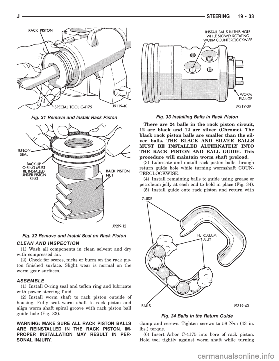
(1) Install O-ring seal and teflon ring and lubricate
with power steering fluid.
(2) Install worm shaft to rack piston outside of
housing. Fully seat worm shaft to rack piston and
align worm shaft spiral groove with rack piston ball
guide hole (Fig. 33).
WARNING: MAKE SURE ALL RACK PISTON BALLS
ARE REINSTALLED IN THE RACK PISTON. IM-
PROPER INSTALLATION MAY RESULT IN PER-
SONAL INJURY.There are 24 balls in the rack piston circuit,
12 are black and 12 are silver (Chrome). The
black rack piston balls are smaller than the sil-
ver balls. THE BLACK AND SILVER BALLS
MUST BE INSTALLED ALTERNATELY INTO
THE RACK PISTON AND BALL GUIDE. This
procedure will maintain worm shaft preload.
(3) Lubricate and install rack piston balls through
return guide hole while turning wormshaft COUN-
TERCLOCKWISE.
(4) Install remaining balls to guide using grease or
petroleum jelly at each end to hold in place (Fig. 34).
(5) Install guide onto rack piston and return with
clamp and screws. Tighten screws to 58 Nzm (43 in.
lbs.) torque.
(6) Insert Arbor C-4175 into bore of rack piston.
Hold tool tightly against worm shaft while turning
Fig. 31 Remove and Install Rack Piston
Fig. 32 Remove and Install Seal on Rack Piston
Fig. 33 Installing Balls in Rack Piston
Fig. 34 Balls in the Return Guide
JSTEERING 19 - 33
Page 1372 of 2198
(36) If equipped, install the cruise control wire har-
ness. Install the turn signal stalk by pushing it
straight into the column.
(37) Insert the hazard warning knob in the hazard
warning switch and press it inward. Align and install
the turn signal switch retaining screws. Ensure that
the turn signal switch is properly seated before tight-
ening the screws. Tighten the screws to 4 Nzm (33 in.
lbs.) torque. Thread the hazard warning switch knob
into the switch and pull the knob outward.
(38) Install and seat the upper bearing race in the
key/lock cylinder housing.
(39) Install the upper bearing preload spring, the
canceling cam and the lockplate.
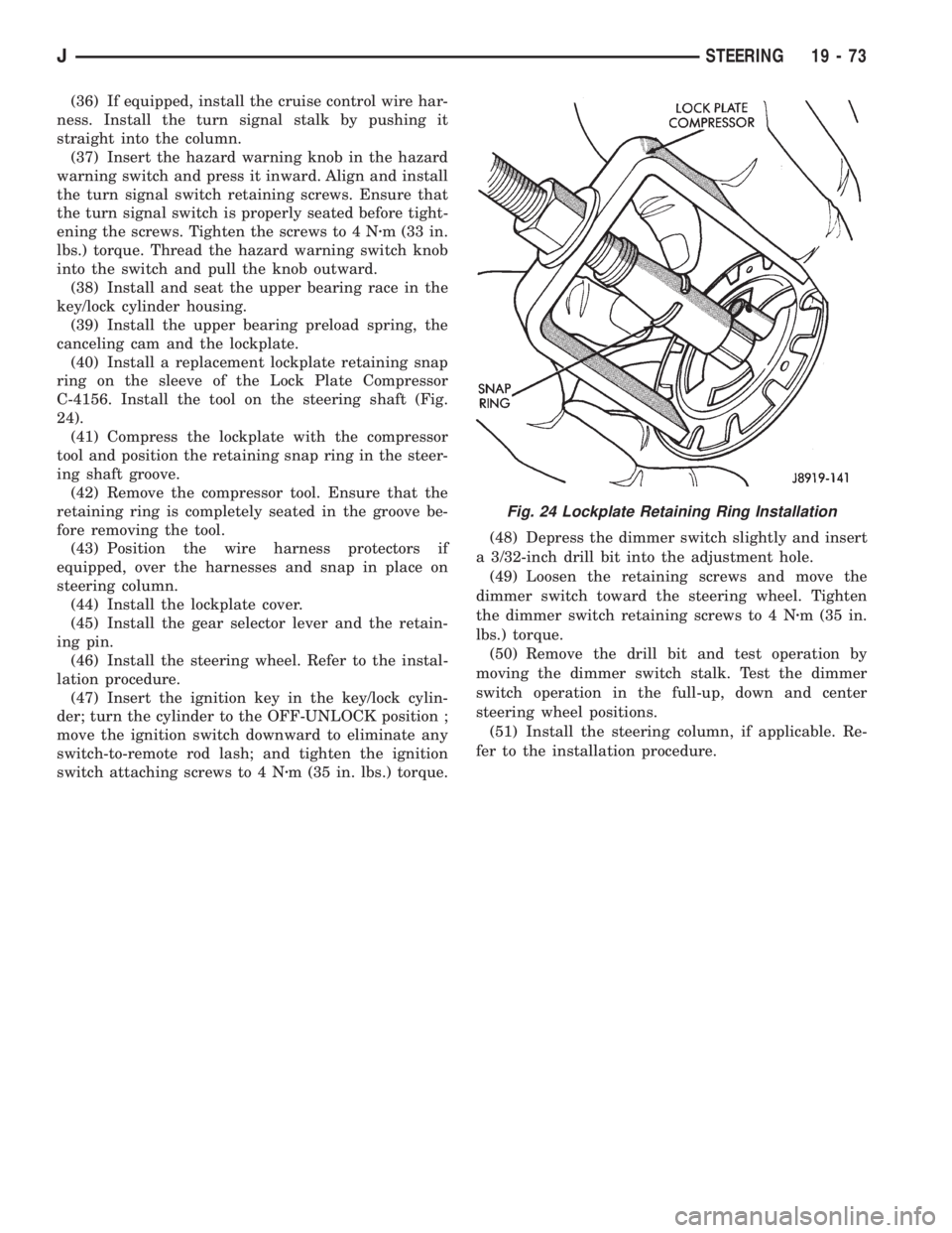
(40) Install a replacement lockplate retaining snap
ring on the sleeve of the Lock Plate Compressor
C-4156. Install the tool on the steering shaft (Fig.
24).
(41) Compress the lockplate with the compressor
tool and position the retaining snap ring in the steer-
ing shaft groove.
(42) Remove the compressor tool. Ensure that the
retaining ring is completely seated in the groove be-
fore removing the tool.
(43) Position the wire harness protectors if
equipped, over the harnesses and snap in place on
steering column.
(44) Install the lockplate cover.
(45) Install the gear selector lever and the retain-
ing pin.
(46) Install the steering wheel. Refer to the instal-
lation procedure.
(47) Insert the ignition key in the key/lock cylin-
der; turn the cylinder to the OFF-UNLOCK position ;
move the ignition switch downward to eliminate any
switch-to-remote rod lash; and tighten the ignition
switch attaching screws to 4 Nzm (35 in. lbs.) torque.(48) Depress the dimmer switch slightly and insert
a 3/32-inch drill bit into the adjustment hole.
(49) Loosen the retaining screws and move the
dimmer switch toward the steering wheel. Tighten
the dimmer switch retaining screws to 4 Nzm (35 in.
lbs.) torque.
(50) Remove the drill bit and test operation by
moving the dimmer switch stalk. Test the dimmer
switch operation in the full-up, down and center
steering wheel positions.
(51) Install the steering column, if applicable. Re-
fer to the installation procedure.
Fig. 24 Lockplate Retaining Ring Installation
JSTEERING 19 - 73
Page 1451 of 2198
CONVERTER STALL TEST
Stall testing involves determining maximum engine
rpm obtainable at full throttle with the rear wheels
locked and the transmission in D range. This test
checks the holding ability of the converter overrun-
ning clutch and both of the transmission clutches.
When stall testing is completed, refer to the Stall
Speed Specifications chart and Stall Speed Diagnosis
guides.
WARNING: NEVER ALLOW ANYONE TO STAND IN
FRONT OF THE VEHICLE DURING A STALL TEST.
ALWAYS BLOCK THE FRONT WHEELS AND APPLY
THE SERVICE AND PARKING BRAKES DURING
THE TEST.
STALL TEST PROCEDURE
(1) Connect tachometer to engine.
(2) Check and adjust transmission fluid level.
(3) Start and run engine until transmission fluid
reaches normal operating temperature.
(4) Block front wheels.
(5) Fully apply service and parking brakes.
(6) Open throttle completely and record maximum
engine rpm registered on tachometer. It will take
from 3 to 10 seconds to reach maximum rpm. How-
ever, once maximum rpm has been achieved,do not
hold wide open throttle for more than 5 sec-
onds.
CAUTION: Stalling the converter causes a rapid in-
crease in fluid temperature. To avoid fluid overheat-
ing, hold wide open throttle for no more than 5
seconds after reaching peak rpm. In addition, if
more than one stall test is required, run the engine
at 1000 rpm with the transmission in Neutral for at
least 20 seconds to cool the fluid.
(7) Stall speeds should be in 1700-2150 rpm range.
CAUTION: If engine exceeds 2150 rpm, release ac-
celerator pedal immediately as transmission clutch
slippage is occurring.
(8) Shift transmission into Neutral. Run engine for
20-30 seconds at 1000 rpm to cool fluid. Then stop
engine, shift transmission into Park and release
brakes.
(9) Refer to Stall Test Diagnosis.
STALL TEST DIAGNOSIS
Stall Speed Too Low
Low stall speeds with a properly tuned engine in-
dicate a torque converter overrunning clutch prob-
lem. The condition should be confirmed by road
testing prior to converter replacement.The converter overrunning clutch is slipping when
stall speeds are 250 to 350 rpm below specified min-
imum.
A converter overrunning clutch failure will result
in sluggish acceleration in all speed ranges. It will
also require greater than normal throttle opening to
maintain cruising speeds.
Stall Speed Too High
If stall speed exceeds 2150 rpm, transmission
clutch slippage is occurring.
Stall Speed Normal But Acceleration Is Sluggish
If stall speeds are within specified range but abnor-
mal throttle opening is required for acceleration, or
to maintain cruise speeds, the converter overrunning
clutch is seized. The torque converter will have to be
replaced.
Converter Noise During Test
A whining noise caused by fluid flow is normal dur-
ing a stall test. However, loud metallic noises indi-
cate a damaged converter. To confirm that noise is
originating from the converter, operate the vehicle at
light throttle in Drive and Neutral on a hoist and lis-
ten for noise from the converter housing.
AIR PRESSURE TEST
Air pressure testing can be used to check clutch
and band operation with the transmission either in
the vehicle, or on the work bench as a final check af-
ter overhaul.
Air pressure testing requires that the oil pan and
valve body be removed from the transmission.
The servo and clutch apply passages are shown in
Figure 8.
Air Test Procedure
(1) Place one or two fingers on the clutch housing
and apply air pressure through front clutch apply
passage (Fig. 8). Piston movement can be felt and a
soft thud heard as the clutch applies.
(2) Place one or two fingers on the clutch housing
and apply air pressure through rear clutch apply
passage (Fig. 8). Piston movement can be felt and a
soft thud heard as the clutch applies.
(3) Apply air pressure to the front servo apply pas-
sage. The servo rod should extend and cause the
band to tighten around the drum. Spring tension
should release the servo when air pressure is re-
moved.
(4) Apply air pressure to the rear servo apply pas-
sage. The servo rod should extend and cause the
band to tighten around the drum. Spring tension
should release the servo when air pressure is re-
moved.
21 - 74 30RH/32RH TRANSMISSION DIAGNOSISJ