1995 JEEP CHEROKEE torque
[x] Cancel search: torquePage 1865 of 2198
channel. Close the rear window curtain zippers and
attach the side snap-on retainers.
(16) Attach all the top cover snap-on retainers to
the upper side retainers located above both doors. As
necessary, slide the mating half of the snap-on re-
tainers so that they will align with the snap-on re-
tainers on the top cover. Tuck the edge of the top
cover inside the side retainer.
(17) Install the door windows by inserting the re-
tainers into the door grommets. Attach the snap-on
retainers located along the bottom edge of the win-
dow to the door retainer.
SPORT BARÐYJ
REMOVAL
(1) Disconnect sound bar. Refer to Group 8F, Audio
Systems for removal and installation procedures.
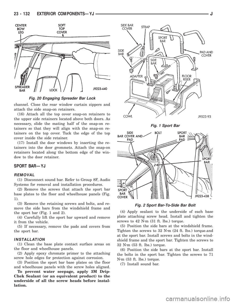
(2) Remove the screws that attach the sport bar
base plates to the floor and wheelhouse panels (Fig.
1).
(3) Remove the retaining screws and bolts, and re-
move the side bars from the windshield frame and
the sport bar (Fig. 1 and 2).
(4) Carefully lift the sport bar upward and remove
it from the vehicle.
(5) If necessary, remove the pads and covers from
the sport bar.
INSTALLATION
(1) Clean the base plate contact surface areas on
the floor and wheelhouse panels.
(2) Apply epoxy chromate primer to the attaching
screw hole edges for protection against corrosion.
(3) Position the sport bar base plates on the floor
and wheelhouse panels with the screw holes aligned.
To prevent water seepage, apply 3M Drip-
Chek Sealant (or an equivalent product) to the
underside of all the screw heads before instal-
lation.(4) Apply sealant to the underside of each base
plate attaching screw head. Install and tighten the
screws to 42 Nzm (31 ft. lbs.) torque.
(5) Position the side bars at the windshield frame.
Tighten the screws to 32 Nzm (24 ft. lbs.) torque.and
at the sport bar. Install screws and bolts in the wind-
shield frame and the sport bar. Tighten the screws to
32 Nzm (53 ft. lbs.) torque.
(6) Position the side bars at the sport bar. Install
the bolts in the sport bar. Tighten the screws to 71
Nzm (53 ft. lbs.) torque.
(7) Install sound bar.
Fig. 20 Engaging Spreader Bar Lock
Fig. 1 Sport Bar
Fig. 2 Sport Bar-To-Side Bar Bolt
23 - 132 EXTERIOR COMPONENTSÐYJJ
Page 1866 of 2198
EXTERNAL SPARE/WHEEL TIRE CARRIERÐYJ
REMOVAL
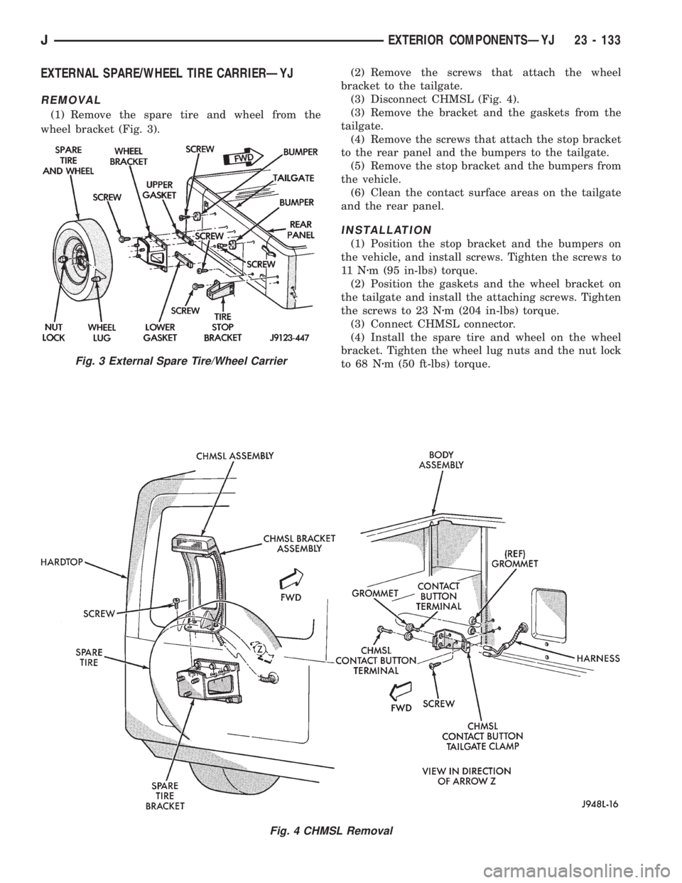
(1) Remove the spare tire and wheel from the
wheel bracket (Fig. 3).(2) Remove the screws that attach the wheel
bracket to the tailgate.
(3) Disconnect CHMSL (Fig. 4).
(3) Remove the bracket and the gaskets from the
tailgate.
(4) Remove the screws that attach the stop bracket
to the rear panel and the bumpers to the tailgate.
(5) Remove the stop bracket and the bumpers from
the vehicle.
(6) Clean the contact surface areas on the tailgate
and the rear panel.
INSTALLATION
(1) Position the stop bracket and the bumpers on
the vehicle, and install screws. Tighten the screws to
11 Nzm (95 in-lbs) torque.
(2) Position the gaskets and the wheel bracket on
the tailgate and install the attaching screws. Tighten
the screws to 23 Nzm (204 in-lbs) torque.
(3) Connect CHMSL connector.
(4) Install the spare tire and wheel on the wheel
bracket. Tighten the wheel lug nuts and the nut lock
to 68 Nzm (50 ft-lbs) torque.
Fig. 4 CHMSL Removal
Fig. 3 External Spare Tire/Wheel Carrier
JEXTERIOR COMPONENTSÐYJ 23 - 133
Page 1871 of 2198
(4) Detach the front three inches of weatherstrip
seal from the door upper frame. Lower the division
channel and tilt it toward the rear of the door.
(5) Remove the vent window glass from the door
frame.
INSTALLATION
(1) Position the vent window glass in the door
frame.
(2) Install the division channel in the door and po-
sition the channel on the window glass.(3) Install the upper attaching screw and the lower
adjustment screw.
(4) Attach the weatherstrip seal to the door upper
frame.
(5) Water test the window and inspect for leaks.
(6) If water leakage is evident, apply windshield
sealant to seal the area or re-align the weatherstrip
seal.
(7) Test the operation and adjustment of the door
window glass.
(8) Install the door waterdam and the trim panel
(Fig. 8 and 10).
FULL-METAL DOOR WINDOW GLASS
REGULATORÐYJ
REMOVAL
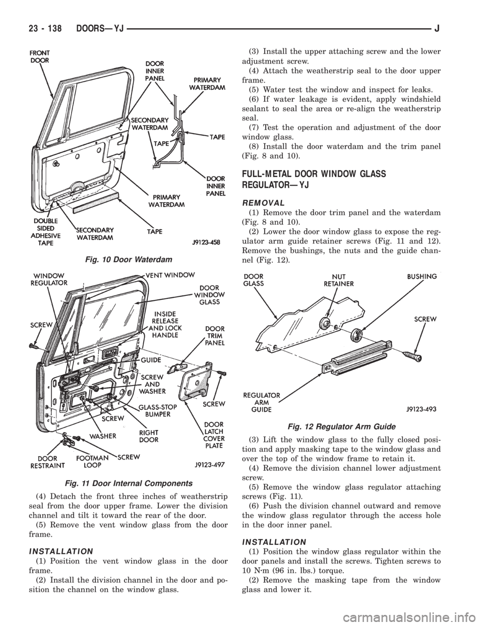
(1) Remove the door trim panel and the waterdam
(Fig. 8 and 10).
(2) Lower the door window glass to expose the reg-
ulator arm guide retainer screws (Fig. 11 and 12).
Remove the bushings, the nuts and the guide chan-
nel (Fig. 12).
(3) Lift the window glass to the fully closed posi-
tion and apply masking tape to the window glass and
over the top of the window frame to retain it.
(4) Remove the division channel lower adjustment
screw.
(5) Remove the window glass regulator attaching
screws (Fig. 11).
(6) Push the division channel outward and remove
the window glass regulator through the access hole
in the door inner panel.
INSTALLATION
(1) Position the window glass regulator within the
door panels and install the screws. Tighten screws to
10 Nzm (96 in. lbs.) torque.
(2) Remove the masking tape from the window
glass and lower it.
Fig. 10 Door Waterdam
Fig. 11 Door Internal Components
Fig. 12 Regulator Arm Guide
23 - 138 DOORSÐYJJ
Page 1874 of 2198
Prior to door adjustment or alignment, the door
latch must be removed to allow the door to close
freely and be properly aligned.
The door latch striker should be adjusted in or out
to allow the door latch to be fully engaged. The door
should be flush with the adjacent body panels.
REPLACEMENT
(1) Mark the outline of the existing hinge on the
body and the door with a wax pencil for installation
alignment reference.
When removing the door or hinge DO NOT
discard the plastic shims or the hinge pin.
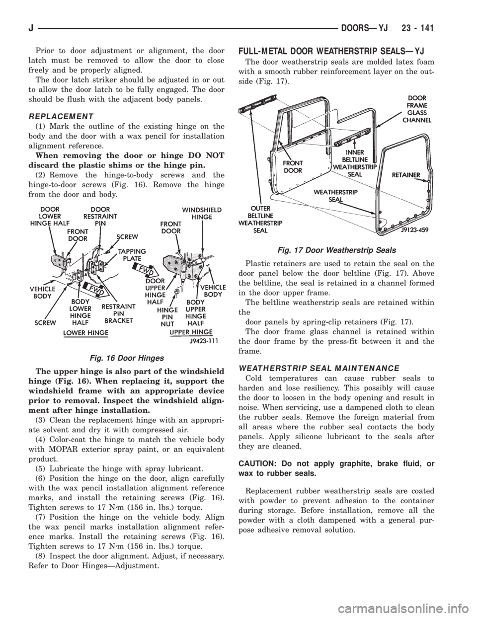
(2) Remove the hinge-to-body screws and the
hinge-to-door screws (Fig. 16). Remove the hinge
from the door and body.
The upper hinge is also part of the windshield
hinge (Fig. 16). When replacing it, support the
windshield frame with an appropriate device
prior to removal. Inspect the windshield align-
ment after hinge installation.
(3) Clean the replacement hinge with an appropri-
ate solvent and dry it with compressed air.
(4) Color-coat the hinge to match the vehicle body
with MOPAR exterior spray paint, or an equivalent
product.
(5) Lubricate the hinge with spray lubricant.
(6) Position the hinge on the door, align carefully
with the wax pencil installation alignment reference
marks, and install the retaining screws (Fig. 16).
Tighten screws to 17 Nzm (156 in. lbs.) torque.
(7) Position the hinge on the vehicle body. Align
the wax pencil marks installation alignment refer-
ence marks. Install the retaining screws (Fig. 16).
Tighten screws to 17 Nzm (156 in. lbs.) torque.
(8) Inspect the door alignment. Adjust, if necessary.
Refer to Door HingesÐAdjustment.
FULL-METAL DOOR WEATHERSTRIP SEALSÐYJ
The door weatherstrip seals are molded latex foam
with a smooth rubber reinforcement layer on the out-
side (Fig. 17).
Plastic retainers are used to retain the seal on the
door panel below the door beltline (Fig. 17). Above
the beltline, the seal is retained in a channel formed
in the door upper frame.
The beltline weatherstrip seals are retained within
the
door panels by spring-clip retainers (Fig. 17).
The door frame glass channel is retained within
the door frame by the press-fit between it and the
frame.
WEATHERSTRIP SEAL MAINTENANCE
Cold temperatures can cause rubber seals to
harden and lose resiliency. This possibly will cause
the door to loosen in the body opening and result in
noise. When servicing, use a dampened cloth to clean
the rubber seals. Remove the foreign material from
all areas where the rubber seal contacts the body
panels. Apply silicone lubricant to the seals after
they are cleaned.
CAUTION: Do not apply graphite, brake fluid, or
wax to rubber seals.
Replacement rubber weatherstrip seals are coated
with powder to prevent adhesion to the container
during storage. Before installation, remove all the
powder with a cloth dampened with a general pur-
pose adhesive removal solution.
Fig. 16 Door Hinges
Fig. 17 Door Weatherstrip Seals
JDOORSÐYJ 23 - 141
Page 1877 of 2198
STATIONARY GLASS
INDEX
page page
Hard Top Quarter Window GlassÐYJ......... 149
Rearview Mirror Retaining BracketÐYJ........ 144
Rearview MirrorÐYJ...................... 144
Stationary Glass Water Leak Detection and
RepairÐYJ........................... 150Windshield Frame Weatherstrip SealÐYJ...... 146
Windshield FrameÐYJ.................... 145
Windshield GlassÐYJ..................... 146
Windshield Reveal MoldingÐYJ............. 144
WINDSHIELD REVEAL MOLDINGÐYJ
REMOVAL
(1) Disengage the reveal molding around the pe-
rimeter of the windshield glass with an appropriate
tool.
(2) Remove the moldings from the windshield
frame.
(3) Inspect the reveal molding retainers. Replace
the molding if it has broken, distorted or ineffective
retainers.
INSTALLATION
(1) Position the reveal moldings on the windshield
frame.
(2) Attach the moldings to the frame by tapping
each molding with a rubber mallet to seat the retain-
ers.
REARVIEW MIRRORÐYJ
REMOVAL/INSTALLATION
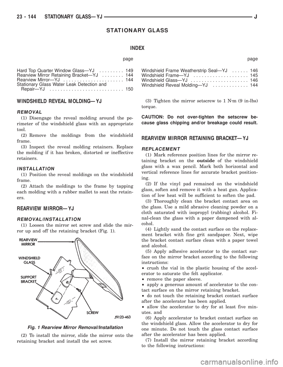
(1) Loosen the mirror set screw and slide the mir-
ror up and off the retaining bracket (Fig. 1).
(2) To install the mirror, slide the mirror onto the
retaining bracket and install the set screw.(3) Tighten the mirror setscrew to 1 Nzm (9 in-lbs)
torque.
CAUTION: Do not over-tighten the setscrew be-
cause glass chipping and/or breakage could result.
REARVIEW MIRROR RETAINING BRACKETÐYJ
REPLACEMENT
(1) Mark reference position lines for the mirror re-
taining bracket on theoutsideof the windshield
glass with a wax pencil. Mark both horizontal and
vertical reference lines for accurate bracket position-
ing.
(2) If the vinyl pad remained on the windshield
glass, soften and remove it with a heat gun. Applica-
tion of low heat will be sufficient to soften the pad.
(3) Thoroughly clean the bracket contact area on
the glass. Use a mild abrasive cleaning powder on a
cloth saturated with isopropyl (rubbing) alcohol. Fi-
nal-clean the glass with a paper dampened with al-
cohol.
(4) Lightly sand the contact surface on the replace-
ment bracket with fine grit sandpaper. Next, wipe
the bracket contact surface clean with a paper towel
and alcohol.
(5) Apply adhesive accelerator to the contact sur-
face on the mirror bracket according to the following
instructions:
²crush the vial in the plastic housing of the accel-
erator to saturate the felt applicator.
²remove the paper sleeve.
²apply a generous amount of accelerator to the con-
tact surface on the mirror retaining bracket.
²do not touch the retaining bracket contact surface
after the accelerator has been applied.
²allow the accelerator to dry for at least five min-
utes. and
(6) Apply accelerator to bracket contact surface on
the windshield glass. Allow the accelerator to dry for
one minute. Do not touch the glass contact surface
after the accelerator has been applied.
(7) Install the mirror retaining bracket according
to the following instructions:
Fig. 1 Rearview Mirror Removal/Installation
23 - 144 STATIONARY GLASSÐYJJ
Page 1881 of 2198
CAUTION: Be prepared to install the windshield
glass immediately after applying the adhesive. The
adhesive begins to cure within 10-15 minutes.
(12) Align the windshield with the grease pencil
marks (or the tape strips) and position windshield on
frame flanges.
(13) Force the windshield glass inward just enough
to wet-out and set urethane. Use care to avoid exces-
sive squeeze-out of adhesive.
(14) Water test the windshield with a cold water
spray after installation. Do not direct high pressure
streams of water directly at the urethane. Use a
moderate spray only. If any leaks are detected, apply
urethane as necessary.
(15) Install the windshield reveal molding and (if
used) remove the masking tape from the inner sur-
face of the glass.
(16) Install all removed components and clean the
vehicle. If necessary, refer to the applicable installa-
tion procedures.
(17) Open windows and liftgate to prevent pres-
sure build-up while the urethane is curing.
(18) Install the rearview mirror on the bracket and
tighten the mirror setscrew with 2 Nzm (15 in-lbs)
torque.
INSTALLATIONÐEXTENDED METHOD
Normally, after a windshield is installed, the rear-
view mirror bracket also requires installation.Do
not install the bracket until after the wind-
shield installation is completed.
(1) Remove all of the original urethane from all the
frame pinchweld flanges. Use an electric hot knife
and a plow-type knife blade to remove the adhesive.
(2) Inspect and repair the windshield frame and
the pinchweld flanges as necessary.
(3) Inspect and replace the reveal molding if the
retainers are damaged.
(4) Prime the frame pinchweld flanges with a ure-
thane base primer. However, if the flange is top-
coated with paint, prime the flanges with a paint
finish primer.This is important because ure-
thane adhesive will not adhere to all top coat
paints.
(5) Install the replacement interior trim molding
(Fig. 5) on the frame pinchweld flanges (Fig. 5).
(6) Install and inspect the fit of the windshield
glass on the pinchweld flanges according to the fol-
lowing instructions:
²Position the windshield glass on the flanges and
adjust the position until it is correctly aligned within
the windshield frame.
²Measure the gap between the frame and the glass
around the entire perimeter of the glass and the
flange.
²The gap should be at least 3 mm (1/8 in) but no
more than 6 mm (1/4 in) at any point around the pe-rimeter, and the flanges should be in complete con-
tact with the glass around the perimeter of the
frame.
(7) If the pinchweld flanges require repair, remove
the windshield glass and straighten, align, or repair
the flange(s) as necessary.
(8) Position the windshield on the flanges and in-
spect the windshield fit again. If the fit is acceptable,
mark windshield final position on the glass and the
frame. The marks (or masking tape) will be used for
installation alignment reference.
(9) If the replacement windshield glass does not
have blackout primer:
²Attach a 25-mm (1-in) wide masking tape band
around the interior side of the glass 16 mm (5/8 in)
from the edge of the glass (Fig. 6).
²Attach the tape only to the interior side of
the glass.
²Thoroughly mix and apply blackout primer to the
16 mm (5/8 in) surface area around the interior side
of the glass (Fig. 6).
²Allow the primer to dry for at least 10-12 minutes.
(10) Cut the urethane adhesive applicator nozzle
(Fig. 7).
(11) Apply a 3-mm (1/8-in) diameter bead of ure-
thane to the surface area.
CAUTION: Be prepared to install the windshield
glass immediately after applying the adhesive. The
adhesive begins to cure within 10-15 minutes.
(12) Align windshield with reference marks (or the
tape strips) and position it on the frame pinchweld
flanges.
(13) Force the windshield glass inward just enough
to wet-out and set urethane. Use care to avoid exces-
sive squeeze-out of adhesive.
(14) Water test the windshield with a cold water
spray after installation. Do not direct high pressure
streams of water directly at the urethane. Use a
moderate spray only. If any leaks are detected, apply
urethane as necessary.
(15) Install the windshield reveal molding and (if
used) remove the masking tape from the inner sur-
face of the glass.
(16) Install all the other previously removed com-
ponents and clean the vehicle. If necessary, refer to
the applicable installation procedures.
(17) Open windows and liftgate to prevent pres-
sure build-up while the urethane is curing.
(18) Install the rearview mirror on the bracket and
tighten the mirror setscrew to 2 Nzm (15 in-lbs)
torque.
23 - 148 STATIONARY GLASSÐYJJ
Page 1884 of 2198
INTERIOR COMPONENTS
INDEX
page page
Add-A-TrunkÐYJ........................ 157
Bucket SeatsÐYJ........................ 153
CarpetÐYJ............................. 156
Floor ConsolesÐYJ...................... 155
Front Shoulder BeltsÐYJ.................. 154
Glove BoxÐYJ.......................... 152
Instrument Cluster and Gauge HousingsÐYJ.... 151Instrument Cluster BezelÐYJ............... 151
Instrument Panel ComponentsÐYJ........... 152
Instrument PanelÐYJ..................... 151
Rear Bench SeatÐYJ..................... 153
Rear Shoulder BeltsÐYJ................... 154
SeatsÐYJ............................. 153
SunvisorsÐYJ.......................... 155
INSTRUMENT PANELÐYJ
The instrument panel is constructed of sheet metal
and is attached to cowl panel with screws. The in-
strument panel and defroster grille pad is attached
to the instrument panel with screws.
INSTRUMENT CLUSTER AND GAUGE HOUSINGSÐ
YJ
REMOVAL
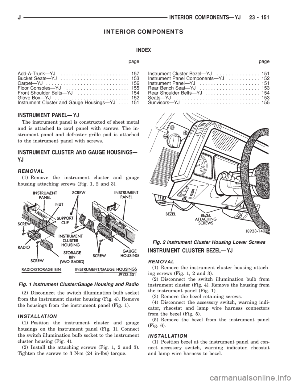
(1) Remove the instrument cluster and gauge
housing attaching screws (Fig. 1, 2 and 3).
(2) Disconnect the switch illumination bulb socket
from the instrument cluster housing (Fig. 4). Remove
the housings from the instrument panel (Fig. 1).
INSTALLATION
(1) Position the instrument cluster and gauge
housings on the instrument panel (Fig. 1). Connect
the switch illumination bulb socket to the instrument
cluster housing (Fig. 4).
(2) Install the attaching screws (Fig. 1, 2 and 3).
Tighten the screws to 3 Nzm (24 in-lbs) torque.
INSTRUMENT CLUSTER BEZELÐYJ
REMOVAL
(1) Remove the instrument cluster housing attach-
ing screws (Fig. 1, 2 and 3).
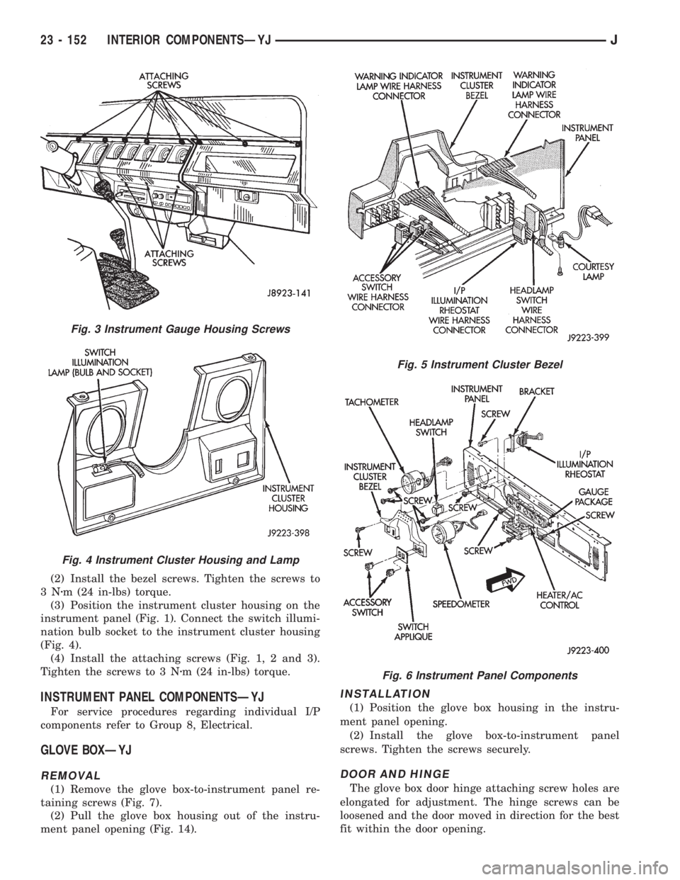
(2) Disconnect the switch illumination bulb from
instrument cluster (Fig. 4). Remove the housing from
the instrument panel (Fig. 1).
(3) Remove the bezel retaining screws.
(4) Disconnect the accessory switch, warning indi-
cator, rheostat and lamp wire harness connectors
from the bezel (Fig. 5).
(5) Remove the bezel from the instrument panel
(Fig. 6).
INSTALLATION
(1) Position bezel at the instrument panel and con-
nect accessory switch, warning indicator, rheostat
and lamp wire harness to bezel.
Fig. 1 Instrument Cluster/Gauge Housing and Radio
Fig. 2 Instrument Cluster Housing Lower Screws
JINTERIOR COMPONENTSÐYJ 23 - 151
Page 1885 of 2198
(2) Install the bezel screws. Tighten the screws to
3Nzm (24 in-lbs) torque.
(3) Position the instrument cluster housing on the
instrument panel (Fig. 1). Connect the switch illumi-
nation bulb socket to the instrument cluster housing
(Fig. 4).
(4) Install the attaching screws (Fig. 1, 2 and 3).
Tighten the screws to 3 Nzm (24 in-lbs) torque.
INSTRUMENT PANEL COMPONENTSÐYJ
For service procedures regarding individual I/P
components refer to Group 8, Electrical.
GLOVE BOXÐYJ
REMOVAL
(1) Remove the glove box-to-instrument panel re-
taining screws (Fig. 7).
(2) Pull the glove box housing out of the instru-
ment panel opening (Fig. 14).
INSTALLATION
(1) Position the glove box housing in the instru-
ment panel opening.
(2) Install the glove box-to-instrument panel
screws. Tighten the screws securely.
DOOR AND HINGE
The glove box door hinge attaching screw holes are
elongated for adjustment. The hinge screws can be
loosened and the door moved in direction for the best
fit within the door opening.
Fig. 3 Instrument Gauge Housing Screws
Fig. 4 Instrument Cluster Housing and Lamp
Fig. 5 Instrument Cluster Bezel
Fig. 6 Instrument Panel Components
23 - 152 INTERIOR COMPONENTSÐYJJ