1995 JEEP CHEROKEE manual transmission
[x] Cancel search: manual transmissionPage 612 of 2198
INSTRUMENT CLUSTER
INDEX
page page
ABS Warning Lamp........................ 2
Brake Warning Lamp....................... 2
Charging System Indicator Lamp............... 3
Cluster Ground............................ 3
Diagram Index............................. 3
Engine Coolant Temperature Gauge............ 1
Engine Coolant Temperature Warning Lamp...... 1
Fuel Gauge.............................. 1
High-Beam Indicator Lamp................... 2
Instrument Cluster......................... 1Low Fuel Warning Lamp..................... 1
Low Washer Fluid Warning Lamp.............. 2
Malfunction Indicator Lamp (MIL)............... 2
Manual Transmission Up-Shift Lamp............ 2
Oil Pressure Gauge........................ 2
Oil Pressure Warning Lamp.................. 2
Seat Belt Indicator Warning Lamp.............. 2
Speedometer............................. 2
Tachometer.............................. 2
Turn Signal Indicator Lamps.................. 2
INSTRUMENT CLUSTER
The instrument cluster contains the gauges and
warning lamps. All gauges have magnetic move-
ments.
When the ignition switch is in the START or RUN
position, circuit A21 feeds circuit F87 through fuse 17
in the fuse block. Circuit A1 from fuse 6 in the Power
Distribution Center (PDC) supplies voltage to circuit
A21. Circuit A1 is HOT at all times.
Circuit F87 connects to the cluster connector to
power the gauges and to the telltale connector to
power the warning lamps.
Circuit E2 from fuse 19 in the fuse block feeds the
illumination lamps. Circuit E2 originates at the head-
lamp switch and continues through fuse 19. The
headlamp switch powers circuit E2 when the parking
lamps or headlamp are ON.
Circuit Z2 provides ground for the indicator lamps
and illumination lamps.
ENGINE COOLANT TEMPERATURE GAUGE
Circuit G20 connects the engine coolant tempera-
ture gauge to the engine coolant temperature sensor.
The sensor is a variable resistor and case grounded to
the engine. Circuit F87 connects to the instrument
cluster left connector and supplies voltage for the
gauge.
The gauge uses two coils. Current passing through
the coils creates a magnetic field. Position of the
gauge needle is controlled by the amount of current
passing through the coils to ground at the sensor.
ENGINE COOLANT TEMPERATURE WARNING
LAMP
Circuit G20 connects the engine coolant tempera-
ture warning lamp to the engine coolant temperature
switch. When the switch closes, battery voltage from
circuit F87 flows through the lamp to ground through
the switch on circuit G20. The engine coolant tem-
perature switch is case grounded to the engine. Cir-cuit F87 connects to the instrument cluster connector
and supplies voltage for the lamp.
Circuit G20 also connects to the warning lamp to
ground when the ignition switch is in the START
position. When the ignition switch is in the START
position, the lamp illuminates for a bulb test.
FUEL GAUGE
The fuel level sensor is a variable resistor. Circuit
G4 connects the fuel level sensor to the fuel gauge in
the instrument cluster. Circuit F87 from fuse 17 in
the fuse block supplies voltage to the fuel gauge. The
fuel level sensor draws voltage from circuit F87
through the fuel gauge on circuit G4. Circuit G4
connects to circuit 57 in the fuel pump module har-
ness. Circuit 57 connects to the fuel level sensor.
Circuit 99 in the fuel pump module harness con-
nects to circuit Z1. Circuit Z1 provides the ground
path for the fuel level sensor. The grounding point for
circuit Z1 is the left side of the cowl panel.
As current flows through the coils in the fuel gauge,
it creates a magnetic field. One of the coils in the
gauge receives fixed current. The other coil is con-
nected to the level sensor. The magnetic field controls
the position of the fuel gauge pointer.
The fuel level sensor contains a variable resistor. As
the position of the float arm on the fuel level sensor
changes, the resistor changes the current flow
through second coil in the fuel gauge. A change in
current flow alters the magnetic field in the fuel
gauge, which changes the pointer position.
LOW FUEL WARNING LAMP
Circuit G4 connects the fuel level sensor to the fuel
gauge. The low fuel level module at the rear of the
gauge monitors resistance in circuit G4. The low fuel
level module powers an light emitting diode (LED)
when the resistance in circuit G4 reaches a calibrated
level. The LED illuminates the Low Fuel indicator.
Refer to Group 8E for additional information.
J8W-40 INSTRUMENT CLUSTERÐXJ VEHICLES 8W - 40 - 1
Page 613 of 2198
OIL PRESSURE GAUGE
The case grounded oil pressure sensor is a variable
resistor that connects to circuit G6. Circuit G6 con-
nects to the oil pressure gauge.
Circuit F87 connects to the instrument cluster con-
nector and supplies battery voltage to oil pressure
gauge. The gauge uses two coils. Current passing
through the coils creates a magnetic field. Position of
the gauge needle is controlled by the amount of cur-
rent passing through the coils to ground at the sen-
sor.
OIL PRESSURE WARNING LAMP
The case grounded oil pressure switch connects to
circuit G6. Circuit G6 connects to the oil pressure
warning lamp. Circuit F87 connects to the instru-
ment cluster connector and supplies battery voltage
to oil pressure lamp.
When the oil pressure switch close, battery voltage
flows through the warning lamp to ground through
the switch, illuminating the lamp.
TACHOMETER
The tachometer module in the instrument cluster
operates the tachometer. The Powertrain Control
Module (PCM) supplies the signal for the tachometer
on circuit G21. Circuit G21 connects to cavity 43 of
the PCM.
SPEEDOMETER
The speedometer and odometer receive a signal
from the vehicle speed sensor on circuit G7. Circuit
G7 also connects to the Powertrain Control Module
(PCM) at cavity 47.
ABS WARNING LAMP
Circuit F87 provides power for the ABS warning
lamp at the instrument cluster. Ground for the ABS
warning lamp is provided by either the ABS control
module or by the ABS power relay when the relay is
not energized. The ABS control module illuminates
the lamp by providing ground on circuit B205.
Circuit B205 splices to connect to circuit B235
through a diode. When the ABS power relay is not
energized, it connects circuit B235 to circuit Z12. The
ground path for the warning lamp is through the di-
ode to circuit B235, through the ABS power relay to
ground on circuit Z12.
The diode between circuit B205 and B235 prevents
voltage from flowing to the ABS control module when
the ABS power relay switches to supply power on cir-
cuit B235.
MALFUNCTION INDICATOR LAMP (MIL)
The PCM provides ground for the instrument clus-
ter malfunction indicator lamp on circuit G3. Circuit
G3 connects to cavity 32 of the PCM. Circuit F87provides voltage for the lamp. The MIL displays the
message CHECK ENGINE when illuminated.
For information regarding diagnostic trouble code
access using the MIL lamp, refer to Group 14, Fuel
Systems.
LOW WASHER FLUID WARNING LAMP
Circuit G29 connects the low washer fluid switch to
the warning lamp in the instrument cluster. Circuit
F12 supplies battery voltage to the switch.
When the low washer fluid switch closes, it con-
nects circuits G29 and F12. Battery voltage from cir-
cuit F12 powers the low washer fluid lamp. Circuit
Z1 at the instrument cluster provides ground to illu-
minate the warning lamp.
SEAT BELT INDICATOR WARNING LAMP
The seat belt indicator warning lamp is activated
by the chime/buzzer on circuit G11. Circuit G11 sup-
plies power to instrument cluster for the lamp. Cir-
cuit Z1 provides ground for the lamp at the cluster.
The chime/buzzer module powers circuit G11 after
it receives an input on circuit G10 indicating the seat
belt switch is open.
HIGH-BEAM INDICATOR LAMP
Circuit L3 supplies power for the high-beam indi-
cator lamp. The ground path for the lamp is through
circuit Z1. If the vehicle has Daytime Running
Lamps (DRL), the DRL module powers circuit L3
through circuit G465. On vehicles not equipped with
DRL, the headlamp switch powers circuit L3.
Circuit Z1 provides ground for the indicator lamp
at the cluster.
TURN SIGNAL INDICATOR LAMPS
Circuits L61 and L60 power for the turn signal in-
dicator lamps. Circuit L61 powers the left indicator
lamp. Circuit L60 powers the right indicator lamp.
Circuit Z1 provides ground for the lamps.
BRAKE WARNING LAMP
Circuit F87 supplies power to the park brake lamp.
Ground for the park brake lamp is supplied through
the case grounded park brake switch or brake warn-
ing switch on circuit G9. Circuit G9 Connects to cir-
cuit B203. Circuit B203 connects to the brake
warning lamp at the instrument cluster.
MANUAL TRANSMISSION UP-SHIFT LAMP
Circuit F87 supplies power for the manual trans-
mission up-shift lamp. The lamp illuminates when
the Powertrain Control Module (PCM) provides
ground for the lamp on circuit K54. Circuit K54 con-
nects to cavity 54 of the PCM.
8W - 40 - 2 8W-40 INSTRUMENT CLUSTERÐXJ VEHICLESJ
Page 1107 of 2198
INSTALLATIONÐYJ VEHICLES
(1) If the engine support bracket was removed, po-
sition the bracket onto the block and install the at-
taching bolts (Fig. 9). Tighten the bolts to 62 Nzm (46
ft. lbs.) torque.
(2) Place the support cushion on the support cush-
ion bracket (Fig. 9). Install the support cushion re-
taining bolts and nuts. Tighten the bolts and nuts to
52 Nzm (38 ft. lbs.) torque.
(3) Install the through bolt and the retaining nut
(Fig. 9). Tighten the through bolt nut to 69 Nzm (51
ft. lbs.) torque.
(4) Remove the engine support.
(5) Lower the vehicle.
(6) Connect negative cable to battery.
ENGINE MOUNTÐREAR
A resilient rubber cushion supports the transmis-
sion at the rear between the transmission extension
housing and the rear support crossmember or skid
plate.
REMOVALÐXJ VEHICLES
(1) Disconnect negative cable from battery.
(2) Raise the vehicle and support the transmission.
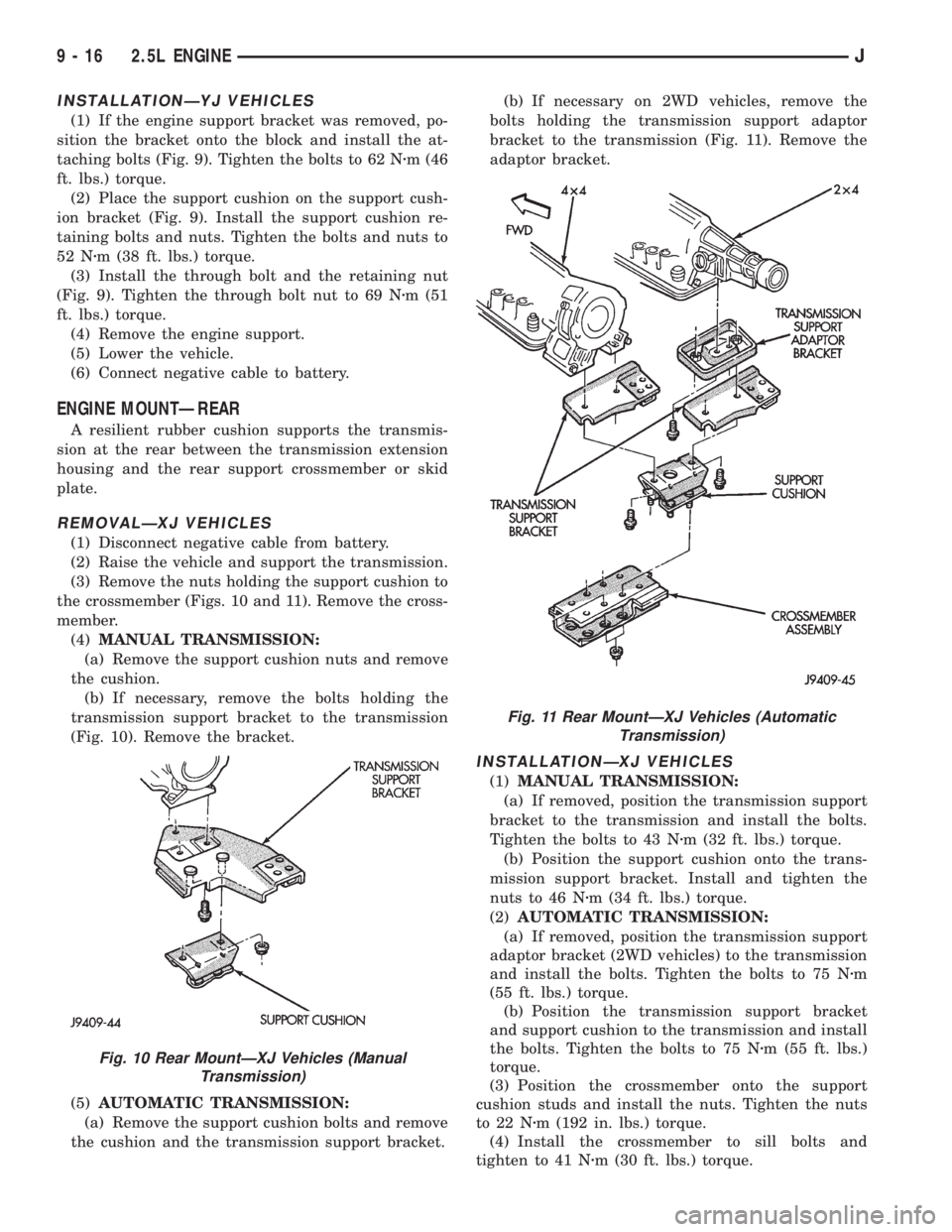
(3) Remove the nuts holding the support cushion to
the crossmember (Figs. 10 and 11). Remove the cross-
member.
(4)MANUAL TRANSMISSION:
(a) Remove the support cushion nuts and remove
the cushion.
(b) If necessary, remove the bolts holding the
transmission support bracket to the transmission
(Fig. 10). Remove the bracket.
(5)AUTOMATIC TRANSMISSION:
(a) Remove the support cushion bolts and remove
the cushion and the transmission support bracket.(b) If necessary on 2WD vehicles, remove the
bolts holding the transmission support adaptor
bracket to the transmission (Fig. 11). Remove the
adaptor bracket.
INSTALLATIONÐXJ VEHICLES
(1)MANUAL TRANSMISSION:
(a) If removed, position the transmission support
bracket to the transmission and install the bolts.
Tighten the bolts to 43 Nzm (32 ft. lbs.) torque.
(b) Position the support cushion onto the trans-
mission support bracket. Install and tighten the
nuts to 46 Nzm (34 ft. lbs.) torque.
(2)AUTOMATIC TRANSMISSION:
(a) If removed, position the transmission support
adaptor bracket (2WD vehicles) to the transmission
and install the bolts. Tighten the bolts to 75 Nzm
(55 ft. lbs.) torque.
(b) Position the transmission support bracket
and support cushion to the transmission and install
the bolts. Tighten the bolts to 75 Nzm (55 ft. lbs.)
torque.
(3) Position the crossmember onto the support
cushion studs and install the nuts. Tighten the nuts
to 22 Nzm (192 in. lbs.) torque.
(4) Install the crossmember to sill bolts and
tighten to 41 Nzm (30 ft. lbs.) torque.
Fig. 10 Rear MountÐXJ Vehicles (Manual
Transmission)
Fig. 11 Rear MountÐXJ Vehicles (Automatic
Transmission)
9 - 16 2.5L ENGINEJ
Page 1108 of 2198
(5) Remove the transmission support.
(6) Lower the vehicle.
(7) Connect negative cable to battery.
REMOVALÐYJ VEHICLES
(1) Disconnect negative cable from battery.
(2) Raise the vehicle and support the transmission.
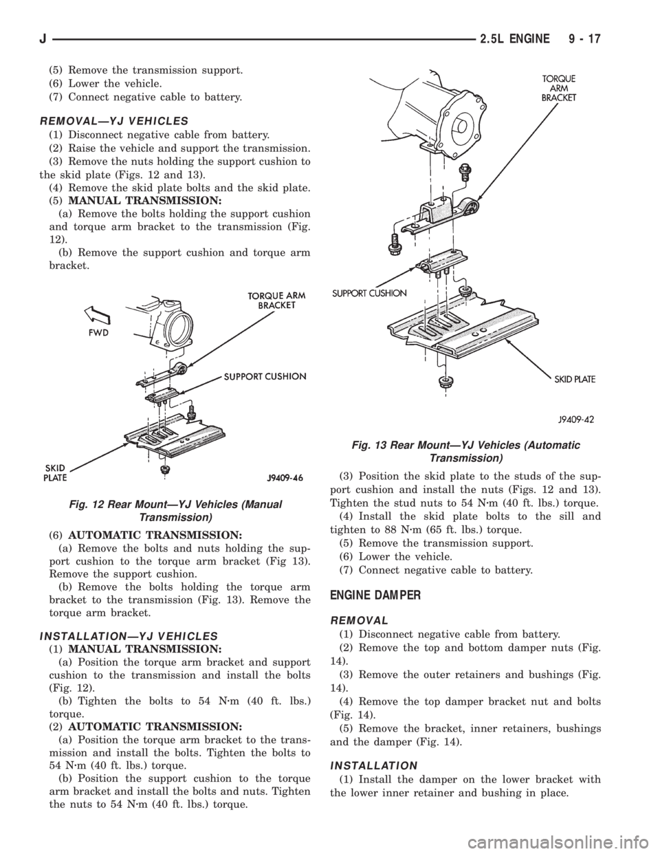
(3) Remove the nuts holding the support cushion to
the skid plate (Figs. 12 and 13).
(4) Remove the skid plate bolts and the skid plate.
(5)MANUAL TRANSMISSION:
(a) Remove the bolts holding the support cushion
and torque arm bracket to the transmission (Fig.
12).
(b) Remove the support cushion and torque arm
bracket.
(6)AUTOMATIC TRANSMISSION:
(a) Remove the bolts and nuts holding the sup-
port cushion to the torque arm bracket (Fig 13).
Remove the support cushion.
(b) Remove the bolts holding the torque arm
bracket to the transmission (Fig. 13). Remove the
torque arm bracket.
INSTALLATIONÐYJ VEHICLES
(1)MANUAL TRANSMISSION:
(a) Position the torque arm bracket and support
cushion to the transmission and install the bolts
(Fig. 12).
(b) Tighten the bolts to 54 Nzm (40 ft. lbs.)
torque.
(2)AUTOMATIC TRANSMISSION:
(a) Position the torque arm bracket to the trans-
mission and install the bolts. Tighten the bolts to
54 Nzm (40 ft. lbs.) torque.
(b) Position the support cushion to the torque
arm bracket and install the bolts and nuts. Tighten
the nuts to 54 Nzm (40 ft. lbs.) torque.(3) Position the skid plate to the studs of the sup-
port cushion and install the nuts (Figs. 12 and 13).
Tighten the stud nuts to 54 Nzm (40 ft. lbs.) torque.
(4) Install the skid plate bolts to the sill and
tighten to 88 Nzm (65 ft. lbs.) torque.
(5) Remove the transmission support.
(6) Lower the vehicle.
(7) Connect negative cable to battery.
ENGINE DAMPER
REMOVAL
(1) Disconnect negative cable from battery.
(2) Remove the top and bottom damper nuts (Fig.
14).
(3) Remove the outer retainers and bushings (Fig.
14).
(4) Remove the top damper bracket nut and bolts
(Fig. 14).
(5) Remove the bracket, inner retainers, bushings
and the damper (Fig. 14).
INSTALLATION
(1) Install the damper on the lower bracket with
the lower inner retainer and bushing in place.
Fig. 12 Rear MountÐYJ Vehicles (Manual
Transmission)
Fig. 13 Rear MountÐYJ Vehicles (Automatic
Transmission)
J2.5L ENGINE 9 - 17
Page 1110 of 2198
(a) Disconnect the power steering hoses from the
fittings at the steering gear.
(b) Drain the pump reservoir.
(c) Cap the fittings on the hoses and steering
gear to prevent foreign material from entering the
system.
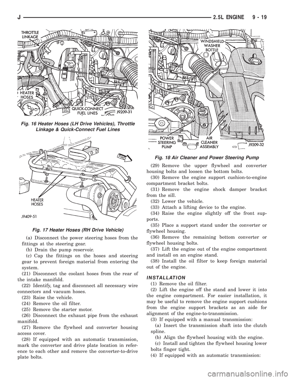
(21) Disconnect the coolant hoses from the rear of
the intake manifold.
(22) Identify, tag and disconnect all necessary wire
connectors and vacuum hoses.
(23) Raise the vehicle.
(24) Remove the oil filter.
(25) Remove the starter motor.
(26) Disconnect the exhaust pipe from the exhaust
manifold.
(27) Remove the flywheel and converter housing
access cover.
(28) If equipped with an automatic transmission,
mark the converter and drive plate location in refer-
ence to each other and remove the converter-to-drive
plate bolts.(29) Remove the upper flywheel and converter
housing bolts and loosen the bottom bolts.
(30) Remove the engine support cushion-to-engine
compartment bracket bolts.
(31) Remove the engine shock damper bracket
from the sill.
(32) Lower the vehicle.
(33) Attach a lifting device to the engine.
(34) Raise the engine slightly off the front sup-
ports.
(35) Place a support stand under the converter or
flywheel housing.
(36) Remove the remaining bottom converter or
flywheel housing bolts.
(37) Lift the engine out of the engine compartment
and install on an engine stand.
(38) Install the oil filter to keep foreign material
out of the engine.
INSTALLATION
(1) Remove the oil filter.
(2) Lift the engine off the stand and lower it into
the engine compartment. For easier installation, it
may be useful to remove the engine support cushions
from the engine support brackets as an aide for
alignment of the engine-to-transmission.
(3) If equipped with a manual transmission:
(a) Insert the transmission shaft into the clutch
spline.
(b) Align the flywheel housing with the engine.
(c) Install and tighten the flywheel housing lower
bolts finger tight.
(4) If equipped with an automatic transmission:
Fig. 16 Heater Hoses (LH Drive Vehicles), Throttle
Linkage & Quick-Connect Fuel Lines
Fig. 17 Heater Hoses (RH Drive Vehicle)
Fig. 18 Air Cleaner and Power Steering Pump
J2.5L ENGINE 9 - 19
Page 1148 of 2198
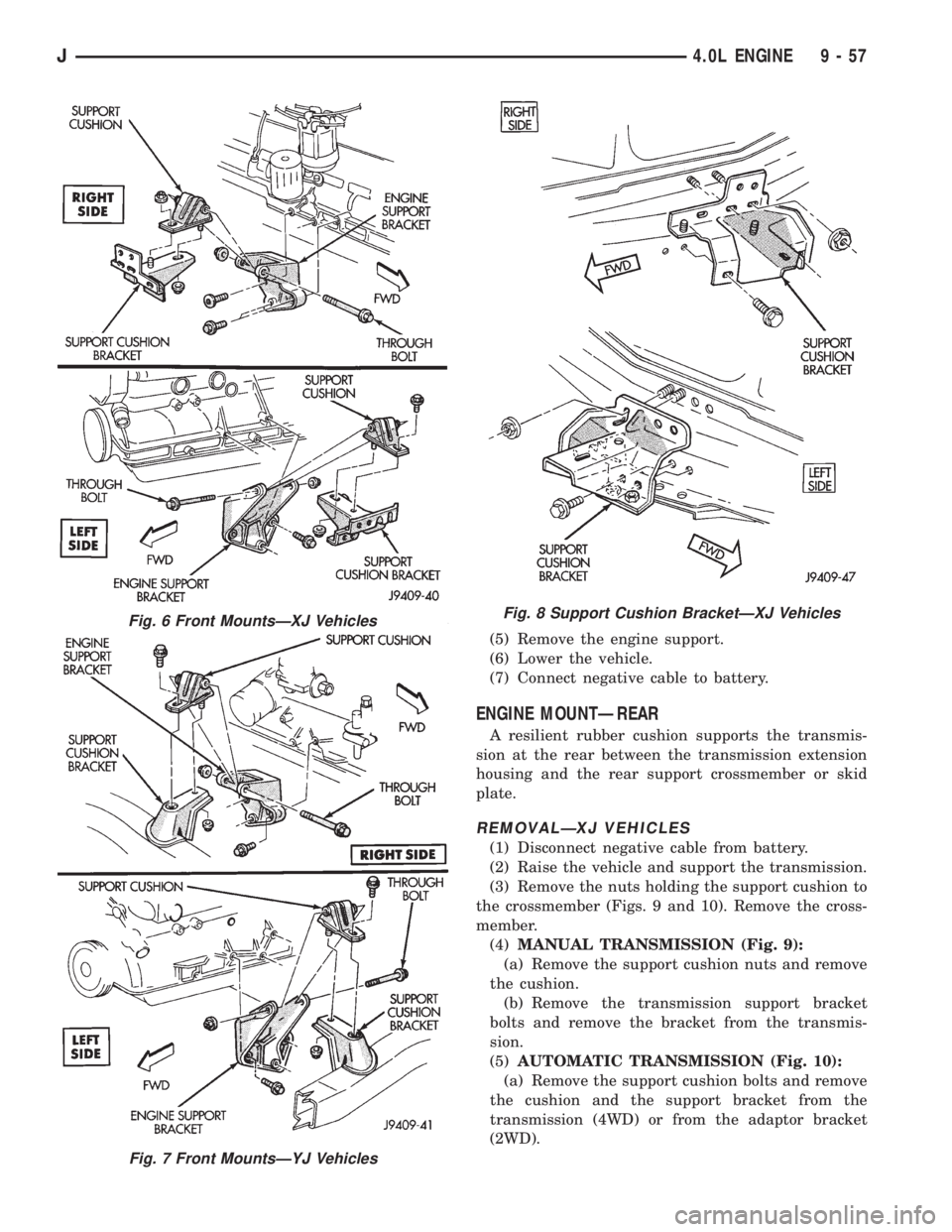
(5) Remove the engine support.
(6) Lower the vehicle.
(7) Connect negative cable to battery.
ENGINE MOUNTÐREAR
A resilient rubber cushion supports the transmis-
sion at the rear between the transmission extension
housing and the rear support crossmember or skid
plate.
REMOVALÐXJ VEHICLES
(1) Disconnect negative cable from battery.
(2) Raise the vehicle and support the transmission.
(3) Remove the nuts holding the support cushion to
the crossmember (Figs. 9 and 10). Remove the cross-
member.
(4)MANUAL TRANSMISSION (Fig. 9):
(a) Remove the support cushion nuts and remove
the cushion.
(b) Remove the transmission support bracket
bolts and remove the bracket from the transmis-
sion.
(5)AUTOMATIC TRANSMISSION (Fig. 10):
(a) Remove the support cushion bolts and remove
the cushion and the support bracket from the
transmission (4WD) or from the adaptor bracket
(2WD).
Fig. 6 Front MountsÐXJ Vehicles
Fig. 7 Front MountsÐYJ Vehicles
Fig. 8 Support Cushion BracketÐXJ Vehicles
J4.0L ENGINE 9 - 57
Page 1149 of 2198
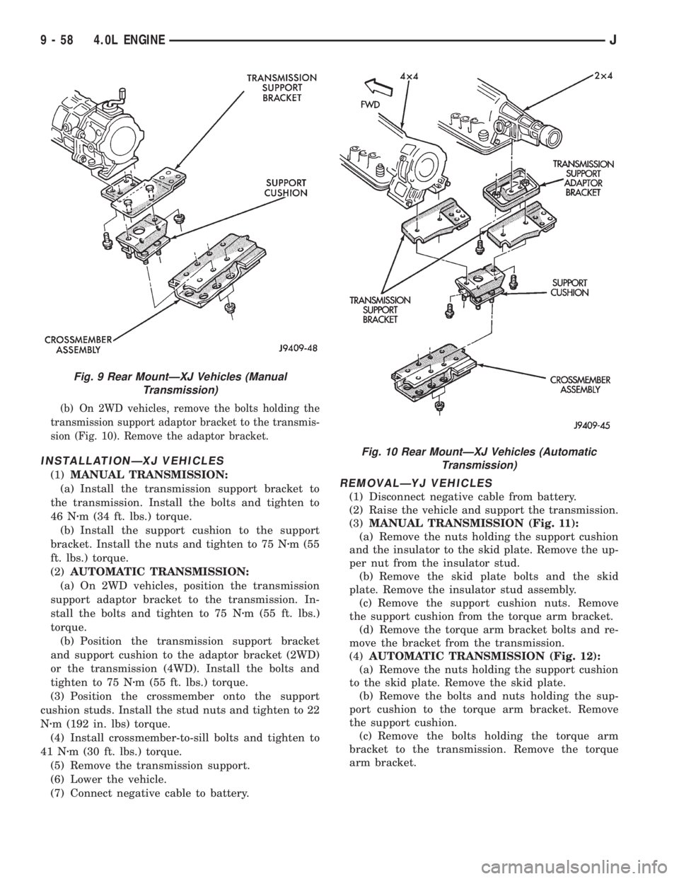
(b) On 2WD vehicles, remove the bolts holding the
transmission support adaptor bracket to the transmis-
sion (Fig. 10). Remove the adaptor bracket.
INSTALLATIONÐXJ VEHICLES
(1)MANUAL TRANSMISSION:
(a) Install the transmission support bracket to
the transmission. Install the bolts and tighten to
46 Nzm (34 ft. lbs.) torque.
(b) Install the support cushion to the support
bracket. Install the nuts and tighten to 75 Nzm (55
ft. lbs.) torque.
(2)AUTOMATIC TRANSMISSION:
(a) On 2WD vehicles, position the transmission
support adaptor bracket to the transmission. In-
stall the bolts and tighten to 75 Nzm (55 ft. lbs.)
torque.
(b) Position the transmission support bracket
and support cushion to the adaptor bracket (2WD)
or the transmission (4WD). Install the bolts and
tighten to 75 Nzm (55 ft. lbs.) torque.
(3) Position the crossmember onto the support
cushion studs. Install the stud nuts and tighten to 22
Nzm (192 in. lbs) torque.
(4) Install crossmember-to-sill bolts and tighten to
41 Nzm (30 ft. lbs.) torque.
(5) Remove the transmission support.
(6) Lower the vehicle.
(7) Connect negative cable to battery.REMOVALÐYJ VEHICLES
(1) Disconnect negative cable from battery.
(2) Raise the vehicle and support the transmission.
(3)MANUAL TRANSMISSION (Fig. 11):
(a) Remove the nuts holding the support cushion
and the insulator to the skid plate. Remove the up-
per nut from the insulator stud.
(b) Remove the skid plate bolts and the skid
plate. Remove the insulator stud assembly.
(c) Remove the support cushion nuts. Remove
the support cushion from the torque arm bracket.
(d) Remove the torque arm bracket bolts and re-
move the bracket from the transmission.
(4)AUTOMATIC TRANSMISSION (Fig. 12):
(a) Remove the nuts holding the support cushion
to the skid plate. Remove the skid plate.
(b) Remove the bolts and nuts holding the sup-
port cushion to the torque arm bracket. Remove
the support cushion.
(c) Remove the bolts holding the torque arm
bracket to the transmission. Remove the torque
arm bracket.
Fig. 9 Rear MountÐXJ Vehicles (Manual
Transmission)
Fig. 10 Rear MountÐXJ Vehicles (Automatic
Transmission)
9 - 58 4.0L ENGINEJ
Page 1150 of 2198
INSTALLATIONÐYJ VEHICLES
(1)MANUAL TRANSMISSION:
(a) Position the torque arm bracket to the trans-
mission. Install the bolts and tighten to 54 Nzm (40
ft. lbs.) torque.
(b) Position the support cushion onto the torque
arm bracket. Install the nuts and tighten to 54 Nzm
(40 ft. lbs.) torque.
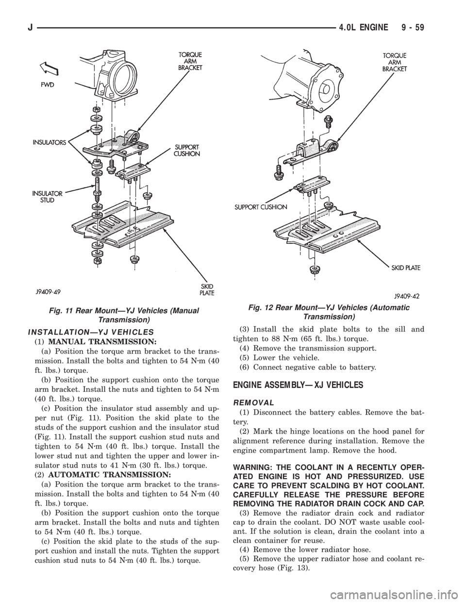
(c) Position the insulator stud assembly and up-
per nut (Fig. 11). Position the skid plate to the
studs of the support cushion and the insulator stud
(Fig. 11). Install the support cushion stud nuts and
tighten to 54 Nzm (40 ft. lbs.) torque. Install the
lower stud nut and tighten the upper and lower in-
sulator stud nuts to 41 Nzm (30 ft. lbs.) torque.
(2)AUTOMATIC TRANSMISSION:
(a) Position the torque arm bracket to the trans-
mission. Install the bolts and tighten to 54 Nzm (40
ft. lbs.) torque.
(b) Position the support cushion onto the torque
arm bracket. Install the bolts and nuts and tighten
to 54 Nzm (40 ft. lbs.) torque.
(c) Position the skid plate to the studs of the sup-
port cushion and install the nuts. Tighten the support
cushion stud nuts to 54 Nzm (40 ft. lbs.) torque.
(3) Install the skid plate bolts to the sill and
tighten to 88 Nzm (65 ft. lbs.) torque.
(4) Remove the transmission support.
(5) Lower the vehicle.
(6) Connect negative cable to battery.
ENGINE ASSEMBLYÐXJ VEHICLES
REMOVAL
(1) Disconnect the battery cables. Remove the bat-
tery.
(2) Mark the hinge locations on the hood panel for
alignment reference during installation. Remove the
engine compartment lamp. Remove the hood.
WARNING: THE COOLANT IN A RECENTLY OPER-
ATED ENGINE IS HOT AND PRESSURIZED. USE
CARE TO PREVENT SCALDING BY HOT COOLANT.
CAREFULLY RELEASE THE PRESSURE BEFORE
REMOVING THE RADIATOR DRAIN COCK AND CAP.
(3) Remove the radiator drain cock and radiator
cap to drain the coolant. DO NOT waste usable cool-
ant. If the solution is clean, drain the coolant into a
clean container for reuse.
(4) Remove the lower radiator hose.
(5) Remove the upper radiator hose and coolant re-
covery hose (Fig. 13).
Fig. 11 Rear MountÐYJ Vehicles (Manual
Transmission)Fig. 12 Rear MountÐYJ Vehicles (Automatic
Transmission)
J4.0L ENGINE 9 - 59