1995 JEEP CHEROKEE wiring
[x] Cancel search: wiringPage 338 of 2198

INSTALLATION
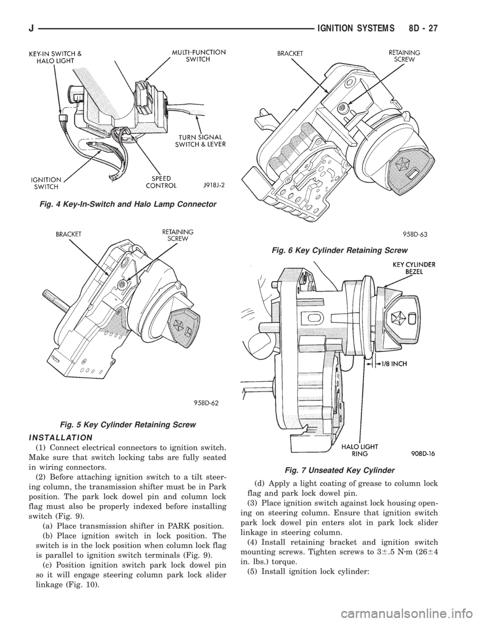
(1) Connect electrical connectors to ignition switch.
Make sure that switch locking tabs are fully seated
in wiring connectors.
(2) Before attaching ignition switch to a tilt steer-
ing column, the transmission shifter must be in Park
position. The park lock dowel pin and column lock
flag must also be properly indexed before installing
switch (Fig. 9).
(a) Place transmission shifter in PARK position.
(b) Place ignition switch in lock position. The
switch is in the lock position when column lock flag
is parallel to ignition switch terminals (Fig. 9).
(c) Position ignition switch park lock dowel pin
so it will engage steering column park lock slider
linkage (Fig. 10).(d) Apply a light coating of grease to column lock
flag and park lock dowel pin.
(3) Place ignition switch against lock housing open-
ing on steering column. Ensure that ignition switch
park lock dowel pin enters slot in park lock slider
linkage in steering column.
(4) Install retaining bracket and ignition switch
mounting screws. Tighten screws to 36.5 Nzm (2664
in. lbs.) torque.
(5) Install ignition lock cylinder:
Fig. 4 Key-In-Switch and Halo Lamp Connector
Fig. 5 Key Cylinder Retaining Screw
Fig. 6 Key Cylinder Retaining Screw
Fig. 7 Unseated Key Cylinder
JIGNITION SYSTEMS 8D - 27
Page 340 of 2198

IGNITION SWITCHÐYJ MODELS
GENERAL INFORMATION
This section will cover the electrical portion
of the ignition switch. To service the mechani-
cal ignition key switch, refer to Group 19,
Steering.
Refer to Group 8W, Wiring for ignition switch wir-
ing circuits.
The ignition switch is mounted under the instru-
ment panel on the lower section of the steering col-
umn. The headlamp dimmer switch is mounted
beside the ignition switch (Fig. 11). Both of these
switches (ignition and dimmer) share the same
mounting screws.
The switch is connected to the ignition key lock as-
sembly by a remote actuator rod. This remote actua-
tor rod fits into an access hole on the bottom of the
ignition switch (Fig. 12).
REMOVAL
(1) Disconnect the negative battery cable at the
battery.
(2) Remove the windshield wiper intermittent con-
trol module and its bracket (if equipped).
(3) Place the ignition key lock in ACCESSORY po-
sition.
(4) Remove the two headlamp dimmer switch at-
taching nuts. Lift the switch from steering column
while disengaging actuator rod.
Before removing dimmer switch, tape the two
remote control actuator rods (ignition switchand dimmer) to the steering column. This will
prevent accidental disengagement from the up-
per part of the steering column.
(5) Remove the ignition switch-to-steering column
attaching screws.
(6) Disengage the ignition switch from the remote
actuator rod by lifting straight up. Remove switch
from steering column.
(7) Remove wiring from switch as follows:
Two electrical connectors are used to connect all
wiring to the ignition switch. One of the connectors is
installed (interlocked) over the top of the other con-
nector. Remove wiring from switch by disconnecting
the (black) harness connector first and then the other
connector. Remove the switch from the vehicle.
SWITCH TESTING
To test the ignition switch circuity and continuity,
proceed as follows. Place the slide bar (on the igni-
tion switch) (Fig. 12) into the detent position to be
tested. An ohmmeter or continuity light may be used
to check switch continuity. Refer to the Ignition
Switch Continuity Tests chart for continuity tests.
Refer to (Fig. 13) for the lettered/numbered terminal
positions.All wiring must be disconnected from
the ignition switch before performing any con-
tinuity testing.
There are five positions on the ignition switch. The
switch positions (in order) are: ACCESSORY, OFF-
LOCK, OFF, ON AND START (Figs. 14 or 15). Each
position has a detent stop (except START), which isFig. 11 Ignition Switch/Headlamp Dimmer SwitchÐ
Typical
Fig. 12 Ignition Switch/Remote Actuator RodÐ
Typical
JIGNITION SYSTEMS 8D - 29
Page 341 of 2198

spring loaded to release when the key is released.
The maximum voltage drop between any two con-
nected terminals should not exceed 12.5 millivolts
per amp. For example: If a 10 amp load is drawn
through the switch, maximum voltage drop should be
10 x 0.0125 or 0.125 volt.
INSTALLATION/ADJUSTMENT
(1) Place the key lock switch in the ACCESSORY
position.
(2) Place the slider bar (in the ignition switch)
(Fig. 12) into the ACCESSORY detent position.
(3) Connect the wiring to the switch as follows: In-
stall the non-black (colored) connector first and then
the black (colored) connector to the ignition switch.
One connector will interlock the other connector.
(4) Slip the remote actuator rod into the access
hole on the switch (Fig. 12). Install the switch to the
steering column. Be careful not to move the slider
bar (on the switch) out of the ACCESSORY detent
position. Remove the ignition switch actuator rod se-
curing-tape from steering column.
(5) Install the two ignition switch-to-steering col-
umn screws finger tight.Do not tighten screws at
this time.
(6) Adjust ignition switch as follows:
(a) Non-tilt steering column: While holding key
lock switch in ACCESSORY position, gently slide
ignition switchup(towards steering wheel). This
will remove slack from switch. Tighten attaching
screws. Do not allow the ignition switch to move
from the ACCESSORY detent position.
(b) Tilt steering column: While holding the key
lock switch in the ACCESSORY position, gently
slide the ignition switchdown(away from steering
wheel) to remove slack from switch. Tighten at-
taching screws. Do not allow the ignition switch to
move from the ACCESSORY detent position.
Because the ignition switch and the headlamp dim-
mer switch share the same two mounting screws, oneof the screws must be removed from the ignition
switch. This must be doneafterthe ignition switch
has been adjusted andbeforethe dimmer switch
has been installed. Remove one screw.Do notre-
move the stud/nut.
(7) Install the headlamp dimmer switch as follows:
Slip switch into actuator rod and position over the ig-
IGNITION SWITCH CONTINUITY TESTS
Fig. 13 Ignition Switch Terminals/Circuits
8D - 30 IGNITION SYSTEMSJ
Page 344 of 2198

INSTRUMENT PANEL AND GAUGES
GROUP INDEX
INSTRUMENT PANEL AND GAUGESÐXJ...... 1INSTRUMENT PANEL AND GAUGESÐYJ..... 24
INSTRUMENT PANEL AND GAUGESÐXJ
CONTENTS
page page
DIAGNOSIS............................. 5
GENERAL INFORMATION.................. 1SERVICE PROCEDURES.................. 17
SPECIFICATIONS........................ 23
GENERAL INFORMATION
Following are general descriptions of major instru-
ment panel components. Refer to Group 8W - Wiring
Diagrams for complete circuit descriptions and dia-
grams.
INSTRUMENT PANEL
Modular instrument panel construction allows all
gauges and controls to be serviced from the front of
the panel. In addition, most instrument panel wiring
or heater and air conditioning components can be ac-
cessed without complete instrument panel removal. If
necessary, the instrument panel can be rolled-down
and removed from the vehicle as an assembly.
Removal of the instrument cluster bezel allows ac-
cess to the cluster assembly, most switches, the cli-
mate controls, and the radio. Removal of the cluster
assembly allows access to the individual gauges, illu-
mination and indicator lamp bulbs, printed circuits,
and most wiring.
Removal of the lower instrument panel allows ac-
cess to heater and air conditioning components, the
fuseblock module, the relay center, and other wiring
and electrical components. Those models equipped
with a driver's-side airbag restraint have a knee
blocker and reinforcement behind the driver's-side
lower instrument panel.
The instrument panel layout is mirror image for
left-hand and right-hand drive vehicles. In most
cases, the diagnosis and service procedures found in
this group are applicable to either vehicle. Although,most illustrations represent only the typical left-hand
drive version. Exceptions are clearly identified as
Right-Hand Drive (RHD).
INSTRUMENT CLUSTERS
Two basic instrument cluster options are offered on
XJ (Cherokee) models. One is referred to as a low-
line cluster, and the other is referred to as a high-
line cluster. Each cluster is divided into two areas:
the gauge area, and the tell-tale area. Each area is
served by a separate printed circuit and wiring con-
nector. Some variations of each cluster exist due to
optional equipment and regulatory requirements.
The low-line cluster includes the following gauges:
²fuel gauge
²speedometer/odometer.
The low-line cluster includes provisions for the fol-
lowing indicator lamps:
²anti-lock brake system lamp
²brake warning lamp
²coolant temperature warning lamp
²four-wheel drive indicator lamps
²generator warning lamp
²headlamp high beam indicator lamp
²low oil pressure warning lamp
²low washer fluid warning lamp
²malfunction indicator (Check Engine) lamp
²seat belt reminder lamp
²turn signal indicator lamps
²upshift indicator lamp.
JINSTRUMENT PANEL AND GAUGES 8E - 1
Page 345 of 2198

The high-line cluster includes the following gauges:
²coolant temperature gauge
²fuel gauge
²oil pressure gauge
²speedometer/odometer
²tachometer
²trip odometer
²voltmeter.
The high-line cluster includes provisions for the fol-
lowing indicator lamps:
²anti-lock brake system lamp
²brake warning lamp
²four-wheel drive indicator lamps
²headlamp high beam indicator lamp
²low fuel warning lamp
²low washer fluid warning lamp
²malfunction indicator (Check Engine) lamp
²seat belt reminder lamp
²turn signal indicator lamps
²upshift indicator lamp.
GAUGES
With the ignition switch in the ON or START posi-
tion, voltage is supplied to all gauges through the in-
strument cluster gauge area printed circuit. With the
ignition switch in the OFF position, voltage is not
supplied to the gauges. A gauge pointer may remain
within the gauge scale after the ignition switch is
OFF. However, the gauges do not accurately indicate
any vehicle condition unless the ignition switch is
ON.
All gauges except the odometer are air core mag-
netic units. Two fixed electromagnetic coils are lo-
cated within the gauge. These coils are wrapped at
right angles to each other around a movable perma-
nent magnet. The movable magnet is suspended
within the coils on one end of a shaft. The gauge nee-
dle is attached to the other end of the shaft.
One of the coils has a fixed current flowing through
it to maintain a constant magnetic field strength.
Current flow through the second coil changes, which
causes changes in its magnetic field strength. The
current flowing through the second coil can be
changed by:
²a variable resistor-type sending unit (fuel level,
coolant temperature, or oil pressure)
²changes in electrical system voltage (voltmeter)
²electronic control circuitry (speedometer/odometer,
tachometer).
The gauge needle moves as the movable permanent
magnet aligns itself to the changing magnetic fields
created around it by the electromagnets.
COOLANT TEMPERATURE GAUGE
The coolant temperature gauge gives an indication
of engine coolant temperature. The coolant tempera-
ture sending unit is a thermistor that changes elec-
trical resistance with changes in engine coolanttemperature. High sending unit resistance causes
low coolant temperature readings. Low resistance
causes high coolant temperature readings.
The gauge will read at the high end of the scale
when the ignition switch is turned to the START po-
sition. This is caused by the bulb test circuit wiring
provision. The same wiring is used for the high-line
cluster with a coolant temperature gauge and the
low-line cluster with a coolant temperature warning
lamp. Sending unit resistance values are shown in a
chart in Specifications.
FUEL GAUGE
The fuel gauge gives an indication of the level of
fuel in the fuel tank. The fuel gauge sending unit has
a float attached to a swing-arm in the fuel tank. The
float moves up or down within the fuel tank as fuel
level changes. As the float moves, an electrical con-
tact on the swing-arm wipes across a resistor coil,
which changes sending unit resistance. High sending
unit resistance causes low fuel level readings. Low
resistance causes high fuel level readings. Sending
unit resistance values are shown in a chart in Spec-
ifications.
OIL PRESSURE GAUGE
The oil pressure gauge gives an indication of en-
gine oil pressure. The combination oil pressure send-
ing unit contains a flexible diaphragm. The
diaphragm moves in response to changes in engine
oil pressure. As the diaphragm moves, sending unit
resistance increases or decreases. High resistance on
the gauge side of the sending unit causes high oil
pressure readings. Low resistance causes low oil
pressure readings. Sending unit resistance values are
shown in a chart in Specifications.
SPEEDOMETER/ODOMETER
The speedometer/odometer gives an indication of
vehicle speed and travel distance. The speedometer
receives a vehicle speed pulse signal from the Vehicle
Speed Sensor (VSS). An electronic integrated circuit
contained within the speedometer reads and analyzes
the pulse signal. It then adjusts the ground path re-
sistance of one electromagnet in the gauge to control
needle movement. It also sends signals to an electric
stepper motor to control movement of the odometer
number rolls. Frequency values for the pulse signal
are shown in a chart in Specifications.
The VSS is mounted to an adapter near the trans-
mission (two-wheel drive) or transfer case (four-wheel
drive) output shaft. The sensor is driven through the
adapter by a speedometer pinion gear. The adapter
and pinion vary with transmission, transfer case,
axle ratio and tire size. Refer to Group 21 - Trans-
mission and Transfer Case for more information.
8E - 2 INSTRUMENT PANEL AND GAUGESÐXJJ
Page 348 of 2198

DIAGNOSIS
GAUGES
If an individual gauge is inoperative, see the diag-
nostic procedure under the heading for that gauge. If
more than one gauge is inoperative, perform the fol-
lowing:
(1) Check fuse 17 (fuse 26 - RHD) in the fuseblock
module. If OK, go to next step. If not OK, replace
fuse.
(2) Check for battery voltage at fuse 17 (fuse 26 -
RHD) with ignition switch in ON position. If OK, go
to next step. If not OK, repair open in circuit from
ignition switch and/or refer to Group 8D - Ignition
Systems for testing of ignition switch.
(3) Turn ignition switch to OFF. Disconnect battery
negative cable. Remove instrument cluster bezel and
cluster assembly. Disconnect gauge cluster connector
A.
(4) Connect battery negative cable. Turn ignition
switch to ON. Check for battery voltage at cavity A8
(cavity A7 - RHD) of cluster connector A. If OK, go to
next step. If not OK, repair open in circuit from fuse
17 (fuse 26 - RHD) as required.
(5) Turn ignition switch to OFF. Disconnect battery
negative cable. Probe cavities A3 and B2 of cluster
connector A. Check for continuity to a good ground.
There should be continuity. If OK, replace gauge
cluster printed circuit. If not OK, repair open in cir-
cuit as required.
COOLANT TEMPERATURE GAUGE
The diagnosis found here addresses an inoperative
gauge condition. If the problem being diagnosed is re-
lated to gauge accuracy, be certain to confirm that
problem is with gauge and not with cooling system
performance. Actual engine coolant temperature
should be checked with a test gauge or thermometer
and compared to gauge readings before you proceed
with gauge diagnosis. Refer to Group 7 - Cooling Sys-
tem for more information.
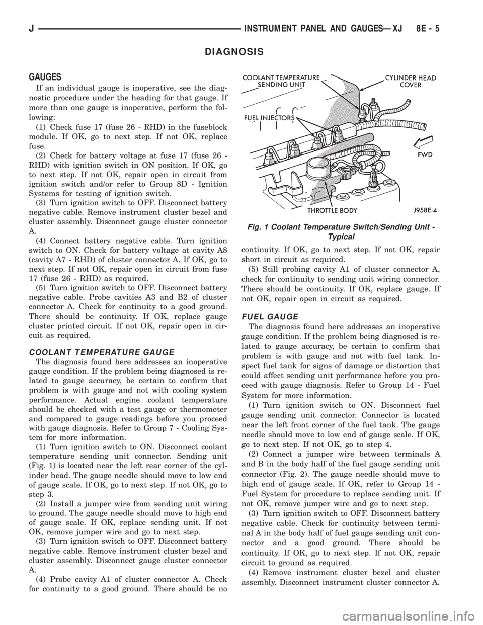
(1) Turn ignition switch to ON. Disconnect coolant
temperature sending unit connector. Sending unit
(Fig. 1) is located near the left rear corner of the cyl-
inder head. The gauge needle should move to low end
of gauge scale. If OK, go to next step. If not OK, go to
step 3.
(2) Install a jumper wire from sending unit wiring
to ground. The gauge needle should move to high end
of gauge scale. If OK, replace sending unit. If not
OK, remove jumper wire and go to next step.
(3) Turn ignition switch to OFF. Disconnect battery
negative cable. Remove instrument cluster bezel and
cluster assembly. Disconnect gauge cluster connector
A.
(4) Probe cavity A1 of cluster connector A. Check
for continuity to a good ground. There should be nocontinuity. If OK, go to next step. If not OK, repair
short in circuit as required.
(5) Still probing cavity A1 of cluster connector A,
check for continuity to sending unit wiring connector.
There should be continuity. If OK, replace gauge. If
not OK, repair open in circuit as required.
FUEL GAUGE
The diagnosis found here addresses an inoperative
gauge condition. If the problem being diagnosed is re-
lated to gauge accuracy, be certain to confirm that
problem is with gauge and not with fuel tank. In-
spect fuel tank for signs of damage or distortion that
could affect sending unit performance before you pro-
ceed with gauge diagnosis. Refer to Group 14 - Fuel
System for more information.
(1) Turn ignition switch to ON. Disconnect fuel
gauge sending unit connector. Connector is located
near the left front corner of the fuel tank. The gauge
needle should move to low end of gauge scale. If OK,
go to next step. If not OK, go to step 4.
(2) Connect a jumper wire between terminals A
and B in the body half of the fuel gauge sending unit
connector (Fig. 2). The gauge needle should move to
high end of gauge scale. If OK, refer to Group 14 -
Fuel System for procedure to replace sending unit. If
not OK, remove jumper wire and go to next step.
(3) Turn ignition switch to OFF. Disconnect battery
negative cable. Check for continuity between termi-
nal A in the body half of fuel gauge sending unit con-
nector and a good ground. There should be
continuity. If OK, go to next step. If not OK, repair
circuit to ground as required.
(4) Remove instrument cluster bezel and cluster
assembly. Disconnect instrument cluster connector A.
Fig. 1 Coolant Temperature Switch/Sending Unit -
Typical
JINSTRUMENT PANEL AND GAUGESÐXJ 8E - 5
Page 349 of 2198

(5) Probe cavity B1 of cluster connector A. Check
for continuity to a good ground. There should be no
continuity. If OK, go to next step. If not OK, repair
short circuit as required.
(6) Still probing cavity B1 of cluster connector A,
check for continuity to cavity B of sending unit body
half connector. There should be continuity. If OK, re-
place gauge. If not OK, repair open circuit as re-
quired.
OIL PRESSURE GAUGE
The diagnosis found here addresses an inoperative
gauge condition. If the problem being diagnosed is re-
lated to gauge accuracy, be certain to confirm that
problem is with gauge and not with engine oiling sys-
tem performance. Actual engine oil pressure should
be checked with a test gauge and compared to gauge
readings before you proceed with gauge diagnosis.
Refer to Group 9 - Engines for more information.
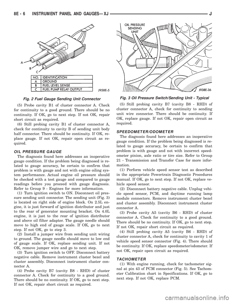
(1) Turn ignition switch to ON. Disconnect oil pres-
sure sending unit connector. The sending unit (Fig. 3)
is located on right side of engine block. On 2.5L en-
gine, it is just forward of ignition distributor and just
to the rear of generator mounting bracket. On 4.0L
engine, it is just to the rear of ignition distributor
and above oil filter adapter. The gauge needle should
move to high end of gauge scale. If OK, go to next
step. If not OK, go to step 3.
(2) Install a jumper wire from sending unit wiring
to ground. The gauge needle should move to low end
of gauge scale. If OK, replace sending unit. If not
OK, remove jumper wire and go to next step.
(3) Turn ignition switch to OFF. Disconnect battery
negative cable. Remove instrument cluster bezel and
cluster assembly. Disconnect instrument cluster con-
nector A.
(4) Probe cavity B7 (cavity B8 - RHD) of cluster
connector A. Check for continuity to a good ground.
There should be no continuity. If OK, go to next step.
If not OK, repair short circuit as required.(5) Still probing cavity B7 (cavity B8 - RHD) of
cluster connector A, check for continuity to sending
unit wire connector. There should be continuity. If
OK, replace gauge. If not OK, repair open circuit as
required.
SPEEDOMETER/ODOMETER
The diagnosis found here addresses an inoperative
gauge condition. If the problem being diagnosed is re-
lated to gauge accuracy, be certain to confirm that
problem is with gauge and not with incorrect speed-
ometer pinion, axle ratio or tire size. Refer to Group
21 - Transmission and Transfer Case for more infor-
mation.
(1) Perform vehicle speed sensor test as described
in the appropriate Powertrain Diagnostic Procedures
manual. If OK, go to next step. If not OK, replace ve-
hicle speed sensor.
(2) Disconnect battery negative cable. Unplug vehi-
cle speed sensor, PCM, and daytime running lamp
module connectors. Remove instrument cluster bezel
and cluster assembly. Disconnect instrument cluster
connector A.
(3) Probe cavity A5 (cavity B6 - RHD) of cluster
connector A. Check for continuity to a good ground.
There should be no continuity. If OK, go to next step.
If not OK, repair short circuit as required.
(4) Still probing cavity A5 (cavity B6 - RHD) of
cluster connector A, check for continuity to cavity 1 of
vehicle speed sensor connector (Fig. 4). There should
be continuity. If OK, replace speedometer/odometer. If
not OK, repair open circuit as required.
TACHOMETER
(1) With engine running, check for tachometer sig-
nal at pin 43 of PCM connector (Fig. 5). See Tachom-
eter Calibration chart in Specifications. If OK, go to
next step. If not OK, replace PCM.
Fig. 2 Fuel Gauge Sending Unit ConnectorFig. 3 Oil Pressure Switch/Sending Unit - Typical
8E - 6 INSTRUMENT PANEL AND GAUGESÐXJJ
Page 363 of 2198

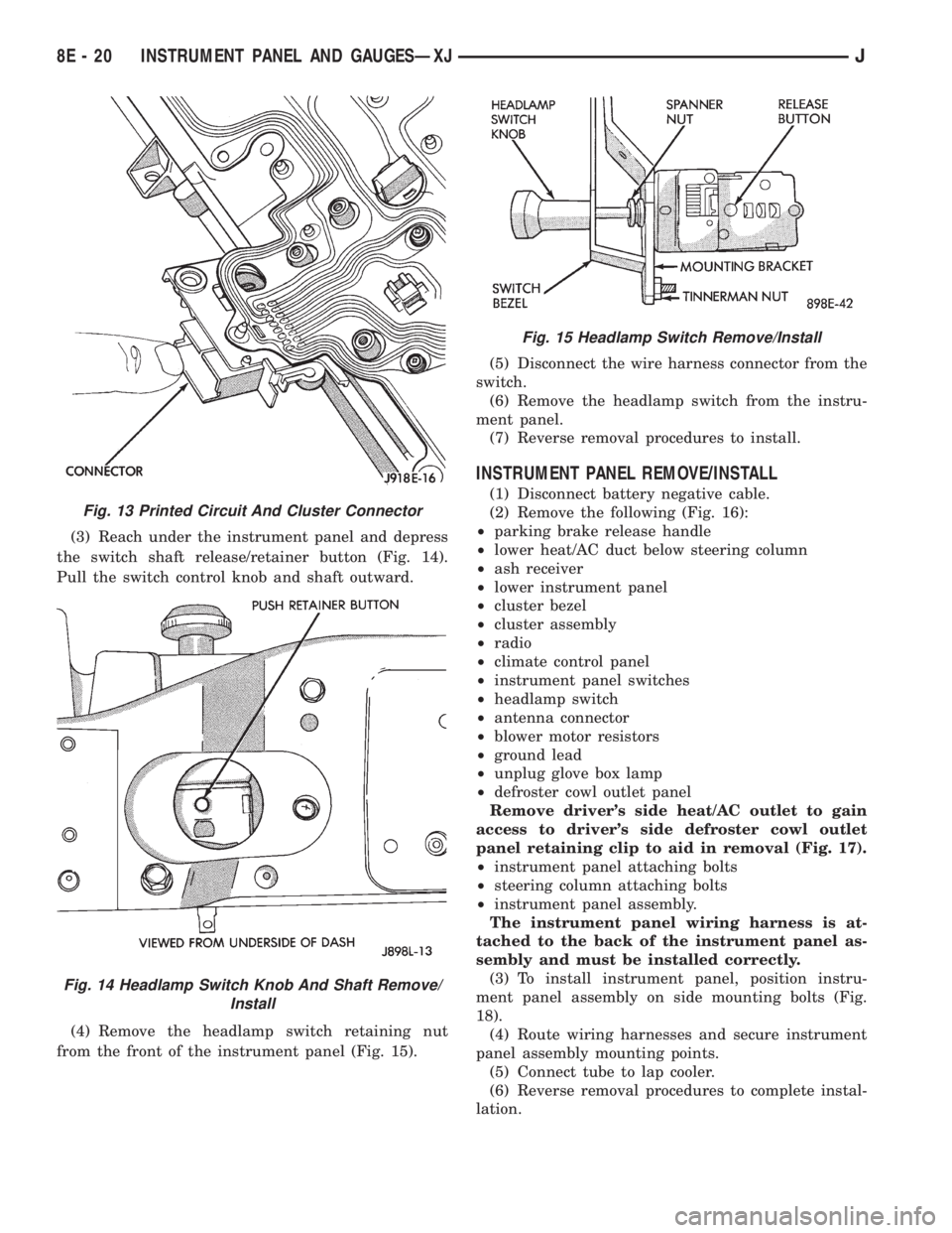
(3) Reach under the instrument panel and depress
the switch shaft release/retainer button (Fig. 14).
Pull the switch control knob and shaft outward.
(4) Remove the headlamp switch retaining nut
from the front of the instrument panel (Fig. 15).(5) Disconnect the wire harness connector from the
switch.
(6) Remove the headlamp switch from the instru-
ment panel.
(7) Reverse removal procedures to install.
INSTRUMENT PANEL REMOVE/INSTALL
(1) Disconnect battery negative cable.
(2) Remove the following (Fig. 16):
²parking brake release handle
²lower heat/AC duct below steering column
²ash receiver
²lower instrument panel
²cluster bezel
²cluster assembly
²radio
²climate control panel
²instrument panel switches
²headlamp switch
²antenna connector
²blower motor resistors
²ground lead
²unplug glove box lamp
²defroster cowl outlet panel
Remove driver's side heat/AC outlet to gain
access to driver's side defroster cowl outlet
panel retaining clip to aid in removal (Fig. 17).
²instrument panel attaching bolts
²steering column attaching bolts
²instrument panel assembly.
The instrument panel wiring harness is at-
tached to the back of the instrument panel as-
sembly and must be installed correctly.
(3) To install instrument panel, position instru-
ment panel assembly on side mounting bolts (Fig.
18).
(4) Route wiring harnesses and secure instrument
panel assembly mounting points.
(5) Connect tube to lap cooler.
(6) Reverse removal procedures to complete instal-
lation.
Fig. 13 Printed Circuit And Cluster Connector
Fig. 14 Headlamp Switch Knob And Shaft Remove/
Install
Fig. 15 Headlamp Switch Remove/Install
8E - 20 INSTRUMENT PANEL AND GAUGESÐXJJ