1995 JEEP CHEROKEE water pump
[x] Cancel search: water pumpPage 1118 of 2198
CAUTION: Engine cylinder head bolts should be re-
used only once. Replace the head bolts if they were
used before or if they have a paint dab on the top
of the bolt.
(6) Coat the threads of bolt No.7, only, with Loctite
PST sealant or equivalent.
(7) Install all head bolts, except No.8 and No.10.
(8) Remove the dowels.
(9) Install No.8 and No.10 head bolts.
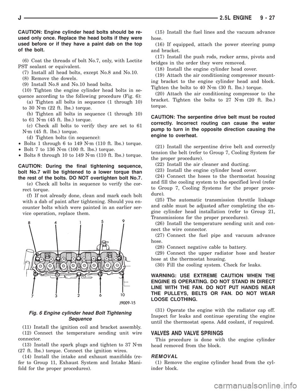
(10) Tighten the engine cylinder head bolts in se-
quence according to the following procedure (Fig. 6):
(a) Tighten all bolts in sequence (1 through 10)
to 30 Nzm (22 ft. lbs.) torque.
(b) Tighten all bolts in sequence (1 through 10)
to 61 Nzm (45 ft. lbs.) torque.
(c) Check all bolts to verify they are set to 61
Nzm (45 ft. lbs.) torque.
(d) Tighten bolts (in sequence):
²Bolts 1 through 6 to 149 Nzm (110 ft. lbs.) torque.
²Bolt 7 to 136 Nzm (100 ft. lbs.) torque.
²Bolts 8 through 10 to 149 Nzm (110 ft. lbs.) torque.
CAUTION: During the final tightening sequence,
bolt No.7 will be tightened to a lower torque than
the rest of the bolts. DO NOT overtighten bolt No.7.
(e) Check all bolts in sequence to verify the cor-
rect torque.
(f) If not already done, clean and mark each bolt
with a dab of paint after tightening. Should you en-
counter bolts which were painted in an earlier ser-
vice operation, replace them.
(11) Install the ignition coil and bracket assembly.
(12) Connect the temperature sending unit wire
connector.
(13) Install the spark plugs and tighten to 37 Nzm
(27 ft. lbs.) torque. Connect the ignition wires.
(14) Install the intake and exhaust manifolds (re-
fer to Group 11, Exhaust System and Intake Mani-
fold for the proper procedures).(15) Install the fuel lines and the vacuum advance
hose.
(16) If equipped, attach the power steering pump
and bracket.
(17) Install the push rods, rocker arms, pivots and
bridges in the order they were removed.
(18) Install the engine cylinder head cover.
(19) Attach the air conditioning compressor mount-
ing bracket to the engine cylinder head and block.
Tighten the bolts to 40 Nzm (30 ft. lbs.) torque.
(20) Attach the air conditioning compressor to the
bracket. Tighten the bolts to 27 Nzm (20 ft. lbs.)
torque.
CAUTION: The serpentine drive belt must be routed
correctly. Incorrect routing can cause the water
pump to turn in the opposite direction causing the
engine to overheat.
(21) Install the serpentine drive belt and correctly
tension the belt (refer to Group 7, Cooling System for
the proper procedure).
(22) Install the air cleaner and ducting.
(23) Install the engine cylinder head cover.
(24) Connect the hoses to the thermostat housing
and fill the cooling system to the specified level (refer
to Group 7, Cooling Systems for the proper proce-
dure).
(25) The automatic transmission throttle linkage
and cable must be adjusted after completing the en-
gine cylinder head installation (refer to Group 21,
Transmissions for the proper procedures).
(26) Install the temperature sending unit and con-
nect the wire connector.
(27) Connect the fuel pipe and vacuum advance
hose.
(28) Connect negative cable to battery.
(29) Connect the upper radiator hose and heater
hose at the thermostat housing.
(30) Fill the cooling system. Check for leaks.
WARNING: USE EXTREME CAUTION WHEN THE
ENGINE IS OPERATING. DO NOT STAND IN DIRECT
LINE WITH THE FAN. DO NOT PUT HANDS NEAR
THE PULLEYS, BELTS OR FAN. DO NOT WEAR
LOOSE CLOTHING.
(31) Operate the engine with the radiator cap off.
Inspect for leaks and continue operating the engine
until the thermostat opens. Add coolant, if required.
VALVES AND VALVE SPRINGS
This procedure is done with the engine cylinder
head removed from the block.
REMOVAL
(1) Remove the engine cylinder head from the cyl-
inder block.
Fig. 6 Engine cylinder head Bolt Tightening
Sequence
J2.5L ENGINE 9 - 27
Page 1140 of 2198
(13) Install the drain plug. Tighten the plug to 34
Nzm (25 ft. lbs.) torque.
(14) Lower the vehicle.
(15) Install the spark plugs. Tighten the plugs to
37 Nzm (27 ft. lbs.) torque.
(16) Fill the oil pan with engine oil to the full
mark on the dipstick level.
(17) Connect negative cable to battery.
REAR MAIN OIL SEALS
REMOVAL
(1) Remove the flywheel or converter drive plate.
Discard the old bolts.
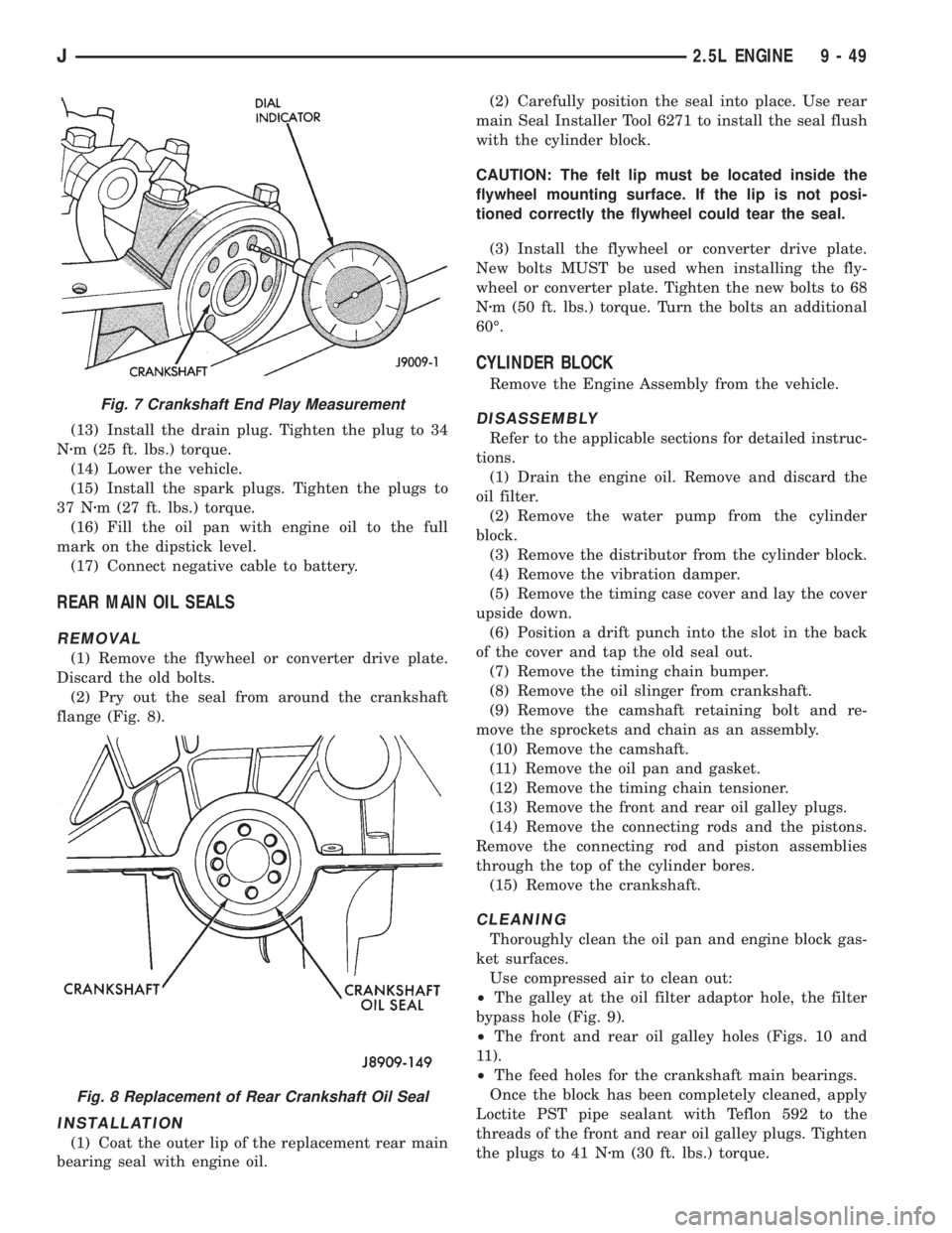
(2) Pry out the seal from around the crankshaft
flange (Fig. 8).
INSTALLATION
(1) Coat the outer lip of the replacement rear main
bearing seal with engine oil.(2) Carefully position the seal into place. Use rear
main Seal Installer Tool 6271 to install the seal flush
with the cylinder block.
CAUTION: The felt lip must be located inside the
flywheel mounting surface. If the lip is not posi-
tioned correctly the flywheel could tear the seal.
(3) Install the flywheel or converter drive plate.
New bolts MUST be used when installing the fly-
wheel or converter plate. Tighten the new bolts to 68
Nzm (50 ft. lbs.) torque. Turn the bolts an additional
60É.
CYLINDER BLOCK
Remove the Engine Assembly from the vehicle.
DISASSEMBLY
Refer to the applicable sections for detailed instruc-
tions.
(1) Drain the engine oil. Remove and discard the
oil filter.
(2) Remove the water pump from the cylinder
block.
(3) Remove the distributor from the cylinder block.
(4) Remove the vibration damper.
(5) Remove the timing case cover and lay the cover
upside down.
(6) Position a drift punch into the slot in the back
of the cover and tap the old seal out.
(7) Remove the timing chain bumper.
(8) Remove the oil slinger from crankshaft.
(9) Remove the camshaft retaining bolt and re-
move the sprockets and chain as an assembly.
(10) Remove the camshaft.
(11) Remove the oil pan and gasket.
(12) Remove the timing chain tensioner.
(13) Remove the front and rear oil galley plugs.
(14) Remove the connecting rods and the pistons.
Remove the connecting rod and piston assemblies
through the top of the cylinder bores.
(15) Remove the crankshaft.
CLEANING
Thoroughly clean the oil pan and engine block gas-
ket surfaces.
Use compressed air to clean out:
²The galley at the oil filter adaptor hole, the filter
bypass hole (Fig. 9).
²The front and rear oil galley holes (Figs. 10 and
11).
²The feed holes for the crankshaft main bearings.
Once the block has been completely cleaned, apply
Loctite PST pipe sealant with Teflon 592 to the
threads of the front and rear oil galley plugs. Tighten
the plugs to 41 Nzm (30 ft. lbs.) torque.
Fig. 7 Crankshaft End Play Measurement
Fig. 8 Replacement of Rear Crankshaft Oil Seal
J2.5L ENGINE 9 - 49
Page 1142 of 2198
ASSEMBLY
Refer to the applicable sections for detailed instruc-
tions.
(1) Install the crankshaft.
(2) Install the connecting rods and the pistons
through the top of the cylinder bores.
(3) Install the front and rear oil galley plugs.
(4) Install the timing chain tensioner.
(5) Install the camshaft.
(6) Install the sprockets and chain as an assembly.
(7) Install the oil slinger to the crankshaft.
(8) Install the timing chain bumper.
(9) Install the timing case cover seal.
(10) Install the timing case cover.(11) Install the oil pan gasket and oil pan.
(12) Install the vibration damper.
(13) Install the water pump. Tighten the mounting
bolts to 31 Nzm (270 in. lbs.) torque.
(14) Remove the distributor from the cylinder
block.
(15) Lubricate the oil filter seal with clean engine
oil. Tighten oil filter to 18 Nzm (13 ft. lbs.) torque.
(16) Install the engine into the vehicle.
(17) Fill the engine with clean lubrication oil (refer
to Group 0, Lubrication and Maintenance).
(18) Fill the cooling system (refer to Group 7, Cool-
ing System for the proper procedures).
J2.5L ENGINE 9 - 51
Page 1151 of 2198
(6) Remove upper radiator support retaining bolts
and remove radiator support.
(7) Remove the fan shroud (Fig. 13) and electric
cooling fan.
(8) Disconnect the transmission fluid cooler tubing
(automatic transmission).
(9) Disconnect radiator fan switch wire connector.
(10)Vehicles with Air Conditioning:
(a) Discharge the A/C condenser.
(b) Remove the service valves and cap the com-
pressor ports.
(11) Remove the radiator or radiator and con-
denser (if equipped with A/C).
(12) Remove the fan assembly from the idler pul-
ley.
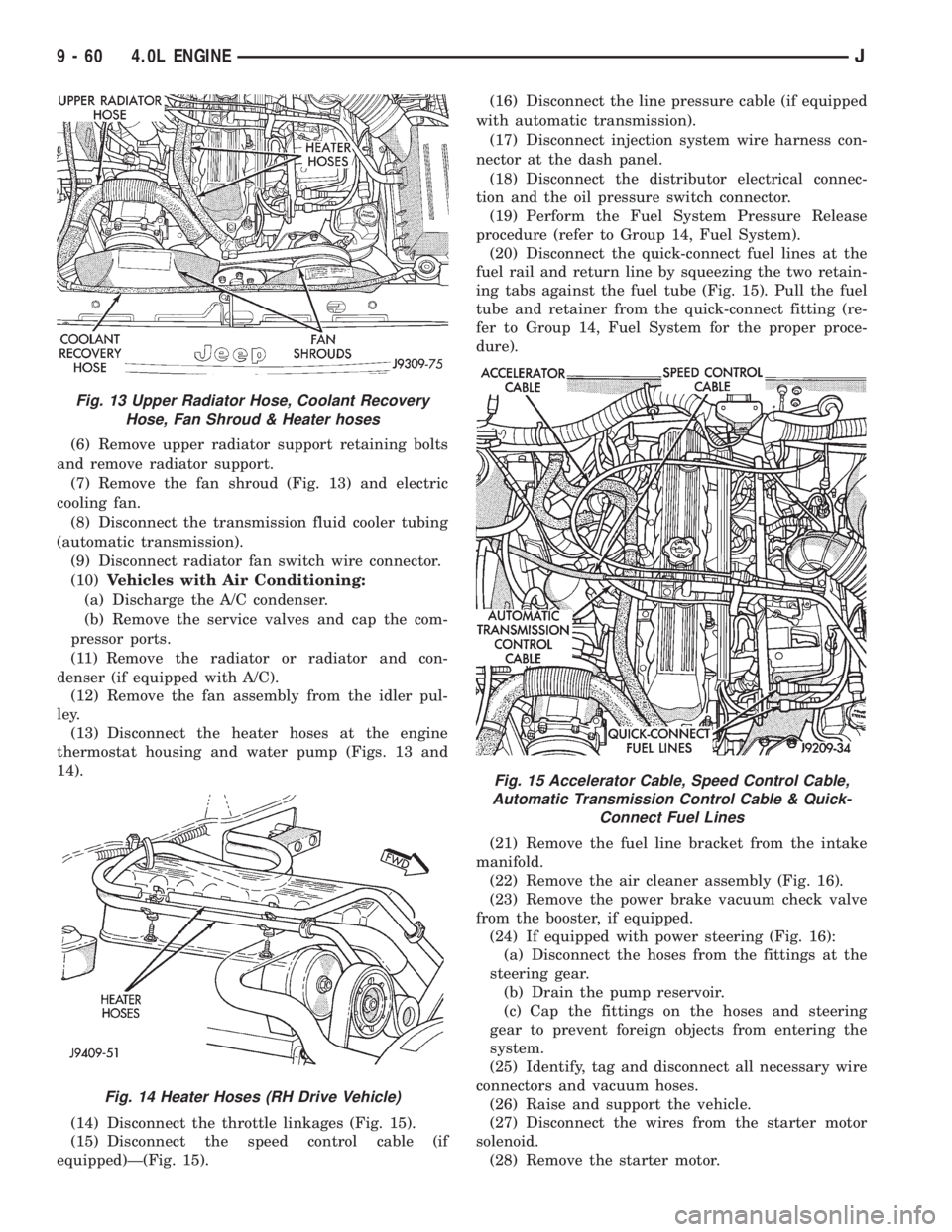
(13) Disconnect the heater hoses at the engine
thermostat housing and water pump (Figs. 13 and
14).
(14) Disconnect the throttle linkages (Fig. 15).
(15) Disconnect the speed control cable (if
equipped)Ð(Fig. 15).(16) Disconnect the line pressure cable (if equipped
with automatic transmission).
(17) Disconnect injection system wire harness con-
nector at the dash panel.
(18) Disconnect the distributor electrical connec-
tion and the oil pressure switch connector.
(19) Perform the Fuel System Pressure Release
procedure (refer to Group 14, Fuel System).
(20) Disconnect the quick-connect fuel lines at the
fuel rail and return line by squeezing the two retain-
ing tabs against the fuel tube (Fig. 15). Pull the fuel
tube and retainer from the quick-connect fitting (re-
fer to Group 14, Fuel System for the proper proce-
dure).
(21) Remove the fuel line bracket from the intake
manifold.
(22) Remove the air cleaner assembly (Fig. 16).
(23) Remove the power brake vacuum check valve
from the booster, if equipped.
(24) If equipped with power steering (Fig. 16):
(a) Disconnect the hoses from the fittings at the
steering gear.
(b) Drain the pump reservoir.
(c) Cap the fittings on the hoses and steering
gear to prevent foreign objects from entering the
system.
(25) Identify, tag and disconnect all necessary wire
connectors and vacuum hoses.
(26) Raise and support the vehicle.
(27) Disconnect the wires from the starter motor
solenoid.
(28) Remove the starter motor.
Fig. 13 Upper Radiator Hose, Coolant Recovery
Hose, Fan Shroud & Heater hoses
Fig. 14 Heater Hoses (RH Drive Vehicle)
Fig. 15 Accelerator Cable, Speed Control Cable,
Automatic Transmission Control Cable & Quick-
Connect Fuel Lines
9 - 60 4.0L ENGINEJ
Page 1153 of 2198
(26) Connect the speed control cable, if equipped.
(27) Connect the throttle cable linkages.
(28) Connect the heater hoses at the engine ther-
mostat housing and water pump.
(29) Install the fan assembly to the idler pulley.
(30) Install the radiator or radiator and condenser
(if equipped with A/C).
(31) Connect the service valves to the A/C compres-
sor ports, if equipped with A/C.
(32) Charge the air conditioner system.
(33) Connect radiator fan switch wire.
(34) Connect automatic transmission fluid cooler
lines, if equipped.
(35) Install the fan shroud, electric cooling fan and
radiator and condenser (if equipped with A/C).
(36) Install upper radiator support.
(37) Connect the upper radiator hose.
(38) Connect the lower radiator hose.
(39) Fill the cooling system with reusable coolant
and/or new coolant.
(40) Align the hood to the scribe marks. Install the
hood.
(41) Connect the vacuum harness connector.
(a) Firmly push the connectors together ensuring
that the retaining tabs are engaged.
(b) Insert the vacuum connector assembly into
the retaining bracket on the intake manifold.
(42) Install the air cleaner assembly.
(43) Install the battery and connect the battery ca-
ble.
WARNING: USE EXTREME CAUTION WHEN THE
ENGINE IS OPERATING. DO NOT STAND IN A DI-
RECT LINE WITH THE FAN. DO NOT PUT YOUR
HANDS NEAR THE PULLEYS, BELTS OR FAN. DO
NOT WEAR LOOSE CLOTHING.
(44) Start the engine, inspect for leaks and correct
the fluid levels, as necessary.
ENGINE ASSEMBLYÐYJ VEHICLES
REMOVAL
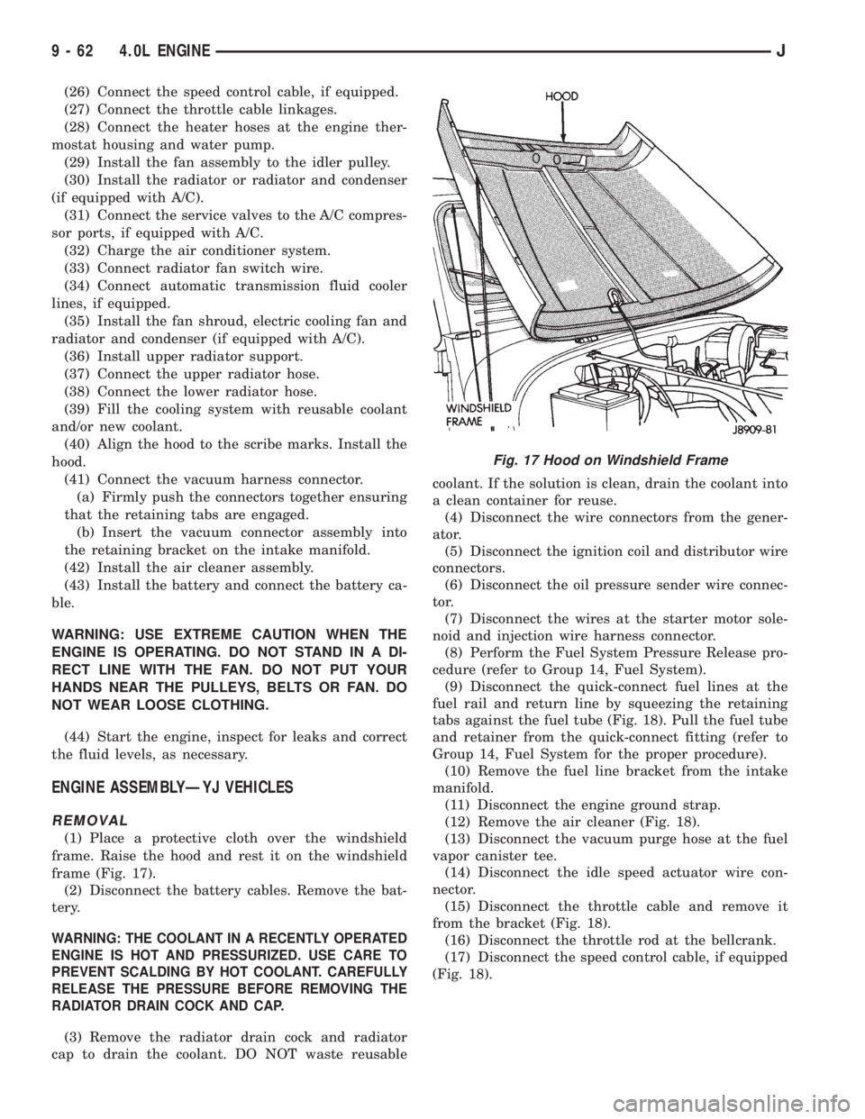
(1) Place a protective cloth over the windshield
frame. Raise the hood and rest it on the windshield
frame (Fig. 17).
(2) Disconnect the battery cables. Remove the bat-
tery.
WARNING: THE COOLANT IN A RECENTLY OPERATED
ENGINE IS HOT AND PRESSURIZED. USE CARE TO
PREVENT SCALDING BY HOT COOLANT. CAREFULLY
RELEASE THE PRESSURE BEFORE REMOVING THE
RADIATOR DRAIN COCK AND CAP.
(3) Remove the radiator drain cock and radiator
cap to drain the coolant. DO NOT waste reusablecoolant. If the solution is clean, drain the coolant into
a clean container for reuse.
(4) Disconnect the wire connectors from the gener-
ator.
(5) Disconnect the ignition coil and distributor wire
connectors.
(6) Disconnect the oil pressure sender wire connec-
tor.
(7) Disconnect the wires at the starter motor sole-
noid and injection wire harness connector.
(8) Perform the Fuel System Pressure Release pro-
cedure (refer to Group 14, Fuel System).
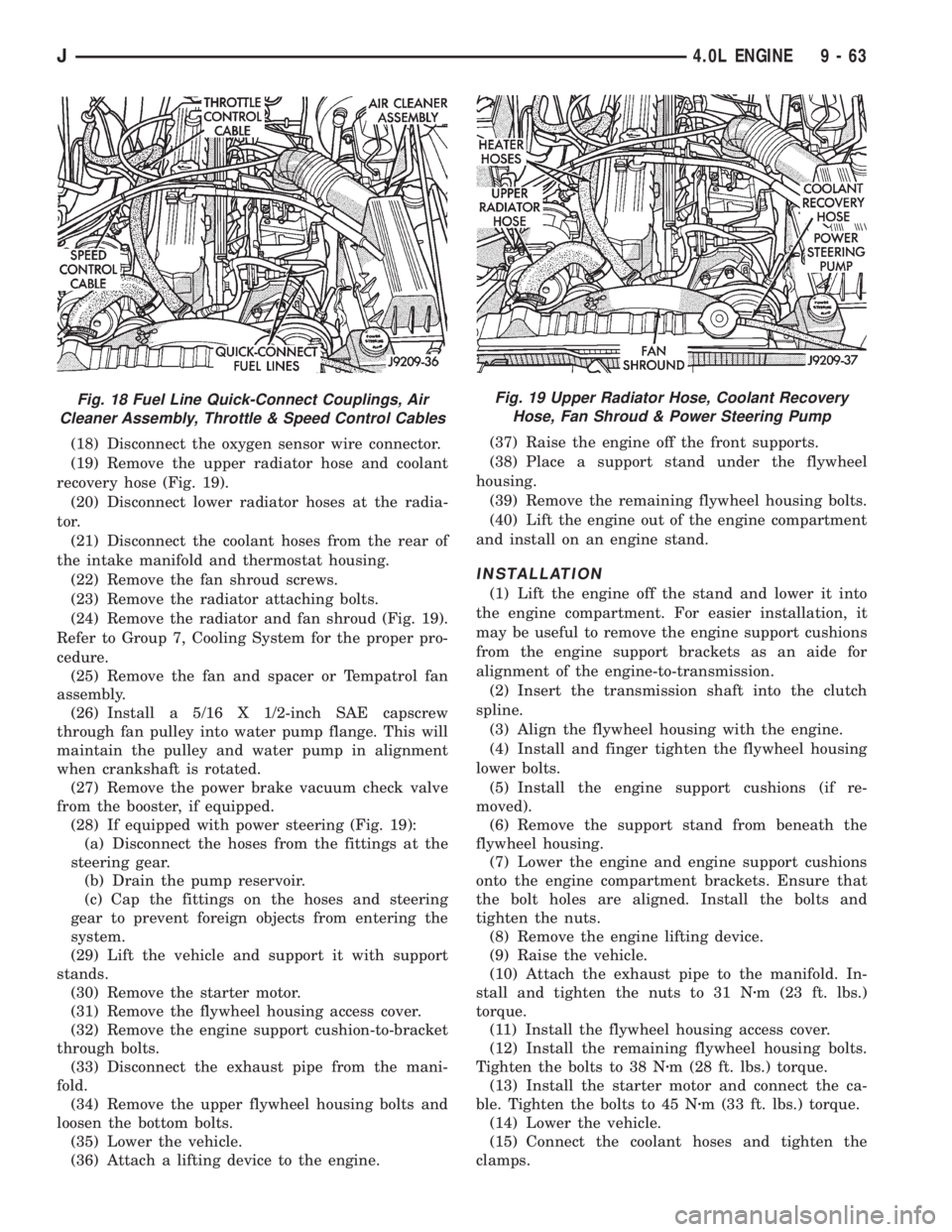
(9) Disconnect the quick-connect fuel lines at the
fuel rail and return line by squeezing the retaining
tabs against the fuel tube (Fig. 18). Pull the fuel tube
and retainer from the quick-connect fitting (refer to
Group 14, Fuel System for the proper procedure).
(10) Remove the fuel line bracket from the intake
manifold.
(11) Disconnect the engine ground strap.
(12) Remove the air cleaner (Fig. 18).
(13) Disconnect the vacuum purge hose at the fuel
vapor canister tee.
(14) Disconnect the idle speed actuator wire con-
nector.
(15) Disconnect the throttle cable and remove it
from the bracket (Fig. 18).
(16) Disconnect the throttle rod at the bellcrank.
(17) Disconnect the speed control cable, if equipped
(Fig. 18).
Fig. 17 Hood on Windshield Frame
9 - 62 4.0L ENGINEJ
Page 1154 of 2198
(18) Disconnect the oxygen sensor wire connector.
(19) Remove the upper radiator hose and coolant
recovery hose (Fig. 19).
(20) Disconnect lower radiator hoses at the radia-
tor.
(21) Disconnect the coolant hoses from the rear of
the intake manifold and thermostat housing.
(22) Remove the fan shroud screws.
(23) Remove the radiator attaching bolts.
(24) Remove the radiator and fan shroud (Fig. 19).
Refer to Group 7, Cooling System for the proper pro-
cedure.
(25) Remove the fan and spacer or Tempatrol fan
assembly.
(26) Install a 5/16 X 1/2-inch SAE capscrew
through fan pulley into water pump flange. This will
maintain the pulley and water pump in alignment
when crankshaft is rotated.
(27) Remove the power brake vacuum check valve
from the booster, if equipped.
(28) If equipped with power steering (Fig. 19):
(a) Disconnect the hoses from the fittings at the
steering gear.
(b) Drain the pump reservoir.
(c) Cap the fittings on the hoses and steering
gear to prevent foreign objects from entering the
system.
(29) Lift the vehicle and support it with support
stands.
(30) Remove the starter motor.
(31) Remove the flywheel housing access cover.
(32) Remove the engine support cushion-to-bracket
through bolts.
(33) Disconnect the exhaust pipe from the mani-
fold.
(34) Remove the upper flywheel housing bolts and
loosen the bottom bolts.
(35) Lower the vehicle.
(36) Attach a lifting device to the engine.(37) Raise the engine off the front supports.
(38) Place a support stand under the flywheel
housing.
(39) Remove the remaining flywheel housing bolts.
(40) Lift the engine out of the engine compartment
and install on an engine stand.
INSTALLATION
(1) Lift the engine off the stand and lower it into
the engine compartment. For easier installation, it
may be useful to remove the engine support cushions
from the engine support brackets as an aide for
alignment of the engine-to-transmission.
(2) Insert the transmission shaft into the clutch
spline.
(3) Align the flywheel housing with the engine.
(4) Install and finger tighten the flywheel housing
lower bolts.
(5) Install the engine support cushions (if re-
moved).
(6) Remove the support stand from beneath the
flywheel housing.
(7) Lower the engine and engine support cushions
onto the engine compartment brackets. Ensure that
the bolt holes are aligned. Install the bolts and
tighten the nuts.
(8) Remove the engine lifting device.
(9) Raise the vehicle.
(10) Attach the exhaust pipe to the manifold. In-
stall and tighten the nuts to 31 Nzm (23 ft. lbs.)
torque.
(11) Install the flywheel housing access cover.
(12) Install the remaining flywheel housing bolts.
Tighten the bolts to 38 Nzm (28 ft. lbs.) torque.
(13) Install the starter motor and connect the ca-
ble. Tighten the bolts to 45 Nzm (33 ft. lbs.) torque.
(14) Lower the vehicle.
(15) Connect the coolant hoses and tighten the
clamps.
Fig. 18 Fuel Line Quick-Connect Couplings, Air
Cleaner Assembly, Throttle & Speed Control CablesFig. 19 Upper Radiator Hose, Coolant Recovery
Hose, Fan Shroud & Power Steering Pump
J4.0L ENGINE 9 - 63
Page 1155 of 2198
(16) Remove the pulley-to-water pump flange
alignment capscrew and install the fan and spacer or
Tempatrol fan assembly.
(17) Tighten the serpentine drive belt according to
the specifications listed in Group 7, Cooling System.
(18) Install the fan shroud and radiator (refer to
Group 7, Cooling System for the proper procedure).
(19) Connect the radiator hoses.
(20) Connect the throttle valve rod and retainer.
(21) Connect the throttle cable and install the rod.
(22) Install the throttle valve rod spring.
(23) Connect the speed control cable, if equipped.
(24) Connect the oxygen sensor wire connector.
(25) Install the vacuum hose and check valve on
the brake booster.
(26) Connect the coolant temperature sensor wire
connector.
(27) Connect the idle speed actuator wire connec-
tor.
(28) Connect the fuel inlet and return hoses at the
fuel rail. Verify that the quick-connect fitting assem-
bly fits securely over the fuel lines by giving the fuel
lines a firm tug.
(29) Install the fuel line bracket to the intake man-
ifold.
(30) Connect all fuel injection wire connections.
(31) Install the engine ground strap.
(32) Connect the ignition coil wire connector.
(33) Remove the coolant temperature sending unit
to permit air to escape from the block. Fill the cool-
ing system with coolant. Install the coolant tempera-
ture sending unit when the system is filled.
(34) If equipped with power steering:
(a) Remove the protective caps
(b) Connect the hoses to the fittings at the steer-
ing gear. Tighten the nut to 52 Nzm (38 ft. lbs.)
torque.
(c) Fill the pump reservoir with fluid.
(35) Install the battery and connect the battery ca-
bles.
(36) Install the air cleaner bonnet to the throttle
body.
(37) Install the air cleaner.
(38) Lower the hood and secure in place.
(39) Start the engine and inspect for leaks.
(40) Stop the engine and check the fluid levels.
Add fluid, as required.
ENGINE CYLINDER HEAD COVER
A cured gasket is part of the engine cylinder head
cover.
REMOVAL
(1) Disconnect negative cable from battery.
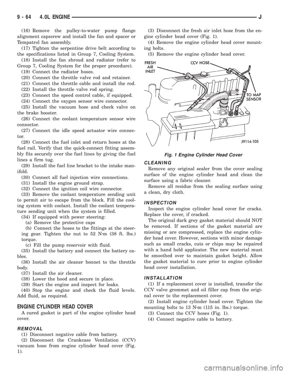
(2) Disconnect the Crankcase Ventilation (CCV)
vacuum hose from engine cylinder head cover (Fig.
1).(3) Disconnect the fresh air inlet hose from the en-
gine cylinder head cover (Fig. 1).
(4) Remove the engine cylinder head cover mount-
ing bolts.
(5) Remove the engine cylinder head cover.
CLEANING
Remove any original sealer from the cover sealing
surface of the engine cylinder head and clean the
surface using a fabric cleaner.
Remove all residue from the sealing surface using
a clean, dry cloth.
INSPECTION
Inspect the engine cylinder head cover for cracks.
Replace the cover, if cracked.
The original dark grey gasket material should NOT
be removed. If sections of the gasket material are
missing or are compressed, replace the engine cylin-
der head cover. However, sections with minor damage
such as small cracks, cuts or chips may be repaired
with a hand held applicator. The new material must
be smoothed over to maintain gasket height. Allow
the gasket material to cure prior to engine cylinder
head cover installation.
INSTALLATION
(1) If a replacement cover is installed, transfer the
CCV valve grommet and oil filler cap from the origi-
nal cover to the replacement cover.
(2) Install engine cylinder head cover. Tighten the
mounting bolts to 13 Nzm (115 in. lbs.) torque.
(3) Connect the CCV hoses (Fig. 1).
(4) Connect negative cable to battery.
Fig. 1 Engine Cylinder Head Cover
9 - 64 4.0L ENGINEJ
Page 1160 of 2198
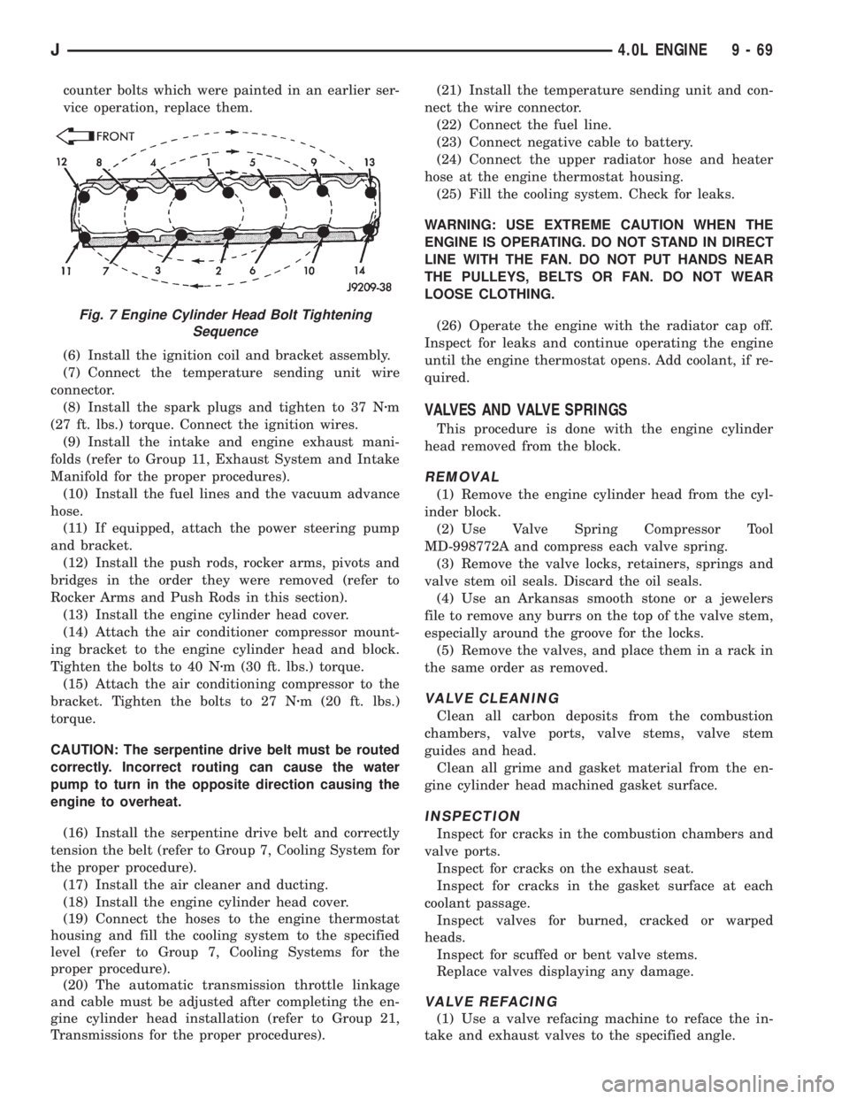
counter bolts which were painted in an earlier ser-
vice operation, replace them.
(6) Install the ignition coil and bracket assembly.
(7) Connect the temperature sending unit wire
connector.
(8) Install the spark plugs and tighten to 37 Nzm
(27 ft. lbs.) torque. Connect the ignition wires.
(9) Install the intake and engine exhaust mani-
folds (refer to Group 11, Exhaust System and Intake
Manifold for the proper procedures).
(10) Install the fuel lines and the vacuum advance
hose.
(11) If equipped, attach the power steering pump
and bracket.
(12) Install the push rods, rocker arms, pivots and
bridges in the order they were removed (refer to
Rocker Arms and Push Rods in this section).
(13) Install the engine cylinder head cover.
(14) Attach the air conditioner compressor mount-
ing bracket to the engine cylinder head and block.
Tighten the bolts to 40 Nzm (30 ft. lbs.) torque.
(15) Attach the air conditioning compressor to the
bracket. Tighten the bolts to 27 Nzm (20 ft. lbs.)
torque.
CAUTION: The serpentine drive belt must be routed
correctly. Incorrect routing can cause the water
pump to turn in the opposite direction causing the
engine to overheat.
(16) Install the serpentine drive belt and correctly
tension the belt (refer to Group 7, Cooling System for
the proper procedure).
(17) Install the air cleaner and ducting.
(18) Install the engine cylinder head cover.
(19) Connect the hoses to the engine thermostat
housing and fill the cooling system to the specified
level (refer to Group 7, Cooling Systems for the
proper procedure).
(20) The automatic transmission throttle linkage
and cable must be adjusted after completing the en-
gine cylinder head installation (refer to Group 21,
Transmissions for the proper procedures).(21) Install the temperature sending unit and con-
nect the wire connector.
(22) Connect the fuel line.
(23) Connect negative cable to battery.
(24) Connect the upper radiator hose and heater
hose at the engine thermostat housing.
(25) Fill the cooling system. Check for leaks.
WARNING: USE EXTREME CAUTION WHEN THE
ENGINE IS OPERATING. DO NOT STAND IN DIRECT
LINE WITH THE FAN. DO NOT PUT HANDS NEAR
THE PULLEYS, BELTS OR FAN. DO NOT WEAR
LOOSE CLOTHING.
(26) Operate the engine with the radiator cap off.
Inspect for leaks and continue operating the engine
until the engine thermostat opens. Add coolant, if re-
quired.
VALVES AND VALVE SPRINGS
This procedure is done with the engine cylinder
head removed from the block.
REMOVAL
(1) Remove the engine cylinder head from the cyl-
inder block.
(2) Use Valve Spring Compressor Tool
MD-998772A and compress each valve spring.
(3) Remove the valve locks, retainers, springs and
valve stem oil seals. Discard the oil seals.
(4) Use an Arkansas smooth stone or a jewelers
file to remove any burrs on the top of the valve stem,
especially around the groove for the locks.
(5) Remove the valves, and place them in a rack in
the same order as removed.
VALVE CLEANING
Clean all carbon deposits from the combustion
chambers, valve ports, valve stems, valve stem
guides and head.
Clean all grime and gasket material from the en-
gine cylinder head machined gasket surface.
INSPECTION
Inspect for cracks in the combustion chambers and
valve ports.
Inspect for cracks on the exhaust seat.
Inspect for cracks in the gasket surface at each
coolant passage.
Inspect valves for burned, cracked or warped
heads.
Inspect for scuffed or bent valve stems.
Replace valves displaying any damage.
VALVE REFACING
(1) Use a valve refacing machine to reface the in-
take and exhaust valves to the specified angle.
Fig. 7 Engine Cylinder Head Bolt Tightening
Sequence
J4.0L ENGINE 9 - 69