1995 JEEP CHEROKEE radio
[x] Cancel search: radioPage 918 of 2198
RADIO
RADIO
When the ignition switch is in the ACCESSORY or
RUN position, it connects circuit A1 from fuse 6 in
the Power Distribution Center (PDC) to circuit A48.
Circuit A48 powers circuit F85 through fuse 13 in the
fuse block. Circuit F85 powers the radio.
Circuit Z1 provides ground for the radio. The an-
tenna connects to the rear of the radio.
RADIO MEMORY
Circuit M1 from fuse 16 in the Power Distribution
Center (PDC) supplies power for the radio memory.
Circuit A7 from fuse 3 in the PDC supplies voltage
to fuse 16. Circuits A7 and M1 are HOT at all times.
RADIO ILLUMINATION
Circuit E2 supplies battery voltage to the radio il-
lumination lamps when the headlamps or parking
lamps are on and the dimmer switch is in the Low or
On positions.
Circuit X5 supplies battery voltage for the radio
clock and station frequency display. Circuit X5 origi-
nates at the radio illumination relay and is fed by ei-
ther circuit F85 or circuit E2 depending on the
switch position inside the relay.
When the headlamps and parking lamps are off,
the radio illumination relay is in its normal At Rest
position. In the At Rest position, the relay connects
circuit F85 from fuse 13 in the fuse block to circuit
X5.
When the headlamps or parking lamps are on, cir-
cuit L90 from the headlamp switch supplies battery
voltage to the coil side of the radio illumination relay.
Circuit Z1 provides ground for the coil side of the re-
lay.
When voltage is present on circuit L90, the radio
illumination relay switches from its At Rest position
to connect circuit E2 to circuit X5.
HELPFUL INFORMATION
²Circuit A48 supplies voltage to fuse 13 in the fuse
block for circuit F85 when the ignition switch is in
the ACCESSORY or RUN positions. In these posi-
tions, the ignition switch connects circuit A1 from
fuse 6 in the PDC to circuit A48.²Circuit A3 from fuse 5 in the PDC supplies power
to the fuse block for fuse 9. Fuse 9 protects circuit
L7. When the headlamps or parking lamps are ON,
the headlamp switch connects circuit L7 to circuit
L90. When the adjustable dimmer switch is in the
LOW to ON positions, it internally connects circuit
L7 to circuit E2. Circuit E2 powers fuse 25 in the
fuse block. Circuit E2 continues through fuse 25.
POWER ANTENNA
The Power Antenna Relay supplies power to raise
and lower the antenna. Circuit F60 from fuse 7 in
the fuse block powers the relay. Circuit Z1 provides
ground for the relay.
When the radio is turned on, circuit X60 from the
radio energizes the relay to raise the antenna.
SPEAKERS
Circuit X53 feeds the left front speakers. Circuit
X55 is the return from the speakers to the radio.
Circuit X54 feeds the right front speakers. Circuit
X56 is the return from the speakers to the radio.
Circuit X51 feeds the left rear speaker. Circuit X57
is the return from the speaker to the radio.
Circuit X52 feeds the right rear speaker. Circuit
X58 is the return from the speaker to the radio.
DIAGRAM INDEX
Component Page
Fuse 3 (PDC).........................8W-47-2, 4
Fuse 5 (PDC).......................8W-47-2, 4, 5
Fuse 6 (PDC).........................8W-47-2, 4
Fuse 7 (PDC).........................8W-47-2, 4
Fuse 9 (Fuse Block)...................8W-47-2, 4, 5
Fuse 13 (Fuse Block)....................8W-47-2, 4
Fuse 16 (PDC)........................8W-47-2, 4
Fuse 25 (Fuse Block)....................8W-47-2, 4
Headlamp Switch.......................8W-47-2, 4
Ignition Switch..........................8W-47-2
LCD Relay...........................8W-47-3, 5
Power Antenna..........................8W-47-6
Power Antenna Relay......................8W-47-6
Radio...........................8W-47-2 thru 8
Speakers............................8W-47-7, 8
J8W-47 AUDIO SYSTEMÐXJ-RHD 8W - 47 - 1
Page 1064 of 2198
CONNECTOR LOCATIONS
GENERAL INFORMATION
This section provides illustrations identifying com-
ponent and connector locations in the vehicle. A con-nector index is provided. Use the wiring diagrams in
each section for connector number identification. Re-
fer to the index for the proper figure number.
CONNECTOR LOCATIONS
Connector # Color Location Fig.
C101......BK ...Front Left of Engine Compartment . .2
C102......BK ...InFront of Washer Fluid Reservoir . .2
C103......BK ...Bottom of Washer Fluid Reservoir . .2
C104......BK ...Bottom of Washer Fluid Reservoir . .2
C105......BK ...TopofWasher Fluid Reservoir.....2
C106......BK ...TopofRadiator Fan Housing......2
C107......BK ...Left Fender Side Shield.........2
C108......BK ...Left Fender Side Shield.........2
C109......BK ...Near Air Cleaner..............2
C110......BK ...Left Corner of Engine Compartment .2
C111......BK ...Rear of Intake Manifold.........4
C112......BK ...OnThrottle Body.............4
C113......BK ...OnThrottle Body.............4
C114......BK ...Rear of Intake Manifold.........4
C115......GN ...Lower Right of I.P.
C116......BK ...Near ABS Control Module
C117......GN ...Center of Dash Panel...........2
C118......BK ...Injector No. 6...............4
C119......BK ...Injector No. 5...............4
C120......BK ...Injector No. 4...............4
C121......BK ...Injector No. 3...............4
C122......BK ...Injector No. 2...............4
C123......BK ...Injector No. 1...............4
C124......BK ...OnEngine, Behind Power
Steering Pump.............4
C125......BK ...OnThermostat Housing.........4
C126......BK ...OnABSControl Module.........7
C127......BK ...Near ABS Control Module........7
C128......BK ...Near Distributor..............4
C129......BK ...Near Center of Dash Panel.......3
C130......GY ...Near Center of Dash Panel.......3
C131......BK ...Near Left Kick Panel
C132......BK ...OnSteering Column...........6
C133......BK ...Near Center of Dash Panel.......3
C134......BK ...Center of Dash Panel...........3
C135......BK ...Below Brake Master Cylinder......3
C136......BK ...Right Corner of Engine Compartment .3
C137......BK ...Right Side of Hood............3
C138......BK ...Near ABS Control Module
C139......BK ...Near ABS Control Module........7
C140......GY ...Near ABS Control Module........7
C141......GN ...Near ABS Control Module........7
C142......BK ...Right Fender Side Shield........3
C143......BK ...Right Fender Side Shield........3
C144......BK ...Right Fender Side Shield........3
C145......BK ...Right Fender Side Shield........3
C146......BK ...Below Battery................3
C147......BK ...Rear of Battery...............5
C148......BK ...AtStarter Motor..............4
C149......BK ...Right Side of Engine Near Distributor .4
C150......BK ...Rear of Generator.............4
C151......BK ...Rear of Generator.............5Connector # Color Location Fig.
C152......BK ...Behind Lens................1
C153......BK ...Left Rear of Radiator Closure Panel .1
C154......BK ...Behind Lens................1
C155......BK ...Behind Lens................1
C156......BK ...Behind Lens................1
C157......BK ...Center of Grille Opening.........1
C158......BK ...Center of Grille Opening.........1
C159......BK ...Behind Lens................1
C160......BK ...Behind Lens................1
C201......GY ...Center Bottom of I.P............8
C202......WT ...Center Bottom of I.P............8
C203......BK ...Behind Right Kick Panel........12
C204......BK ...Right Side of I.P.
C205......BK ...Left Rear of I.P...............8
C206......BK ...Left Rear of I.P...............8
C207......BK ...Near Right Kick Panel..........7
C208......GN ...Near Right Kick Panel..........7
C209......RD ...Behind Right Kick Panel........12
C210......BK ...Behind Fender Side Shield
C211......BK ...Near Right Kick Panel..........7
C212......BK ...Near Right Kick Panel
C213......BK ...Rear of Headlamp Switch.......10
C214......BK ...Rear of I.P., Right of Steering
Column..................9
C215......BK ...Rear of I.P., Right of Steering
Column..................9
C216......BK ...Rear of I.P., Right of Steering
Column.................9
C217......RD ...Rear of I.P., Right of Steering
Column..................9
C218......BK ...Below Stop Lamp Switch........7
C219......BK ...Rear of I.P., Right of Steering
Column.................9
C220......NAT ..Rear of I.P. Cluster...........10
C221......BK ...Rear of I.P. Cluster...........10
C222......NAT ..Rear of I.P., Left of Steering Column .9
C223......BK ...Rear of I.P., Left of Steering Column .9
C224......BK ...Rear of I.P., Left of Steering Column .9
C225......BK ...Rear of I.P., Left of Steering Column .9
C226......BK ...OnSteering Column...........6
C227......BK ...Near ABS Control Module........7
C228......WT ...Center of I.P.
C229......BK ...Center of I.P.
C230......BK ...OnSteering Column...........6
C231......BK ...OnSteering Column...........6
C232......BK ...OnSteering Column...........6
C233......BK ...Center Bottom of I.P............8
C234......BK ...Rear of I.P., Above Ash Receiver . . .8
C235......BK ...Rear of Radio...............9
C236......BR ...Rear of A/C-Heater Controls.....10
C237......BK ...Center Bottom of I.P............8
C238......BK ...Near ABS Control Module........7
J8W-90 CONNECTOR LOCATIONSÐXJ-RHD 8W - 90 - 1
Page 1748 of 2198
²Front fender.
REMOVAL
(1) Remove the front bumper.
(2) Right fender only:
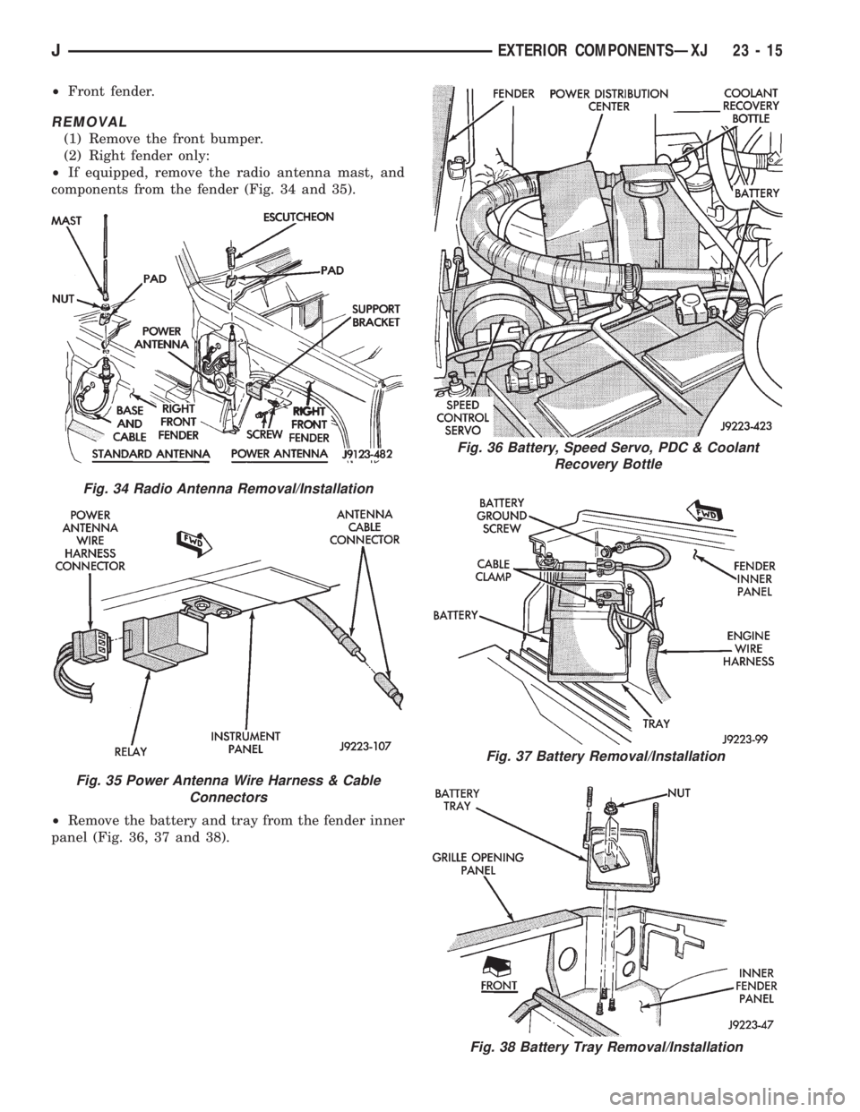
²If equipped, remove the radio antenna mast, and
components from the fender (Fig. 34 and 35).
²Remove the battery and tray from the fender inner
panel (Fig. 36, 37 and 38).
Fig. 36 Battery, Speed Servo, PDC & Coolant
Recovery Bottle
Fig. 37 Battery Removal/Installation
Fig. 38 Battery Tray Removal/Installation
Fig. 34 Radio Antenna Removal/Installation
Fig. 35 Power Antenna Wire Harness & Cable
Connectors
JEXTERIOR COMPONENTSÐXJ 23 - 15
Page 1774 of 2198
DOOR ALIGNMENT ADJUSTMENTÐMAJOR
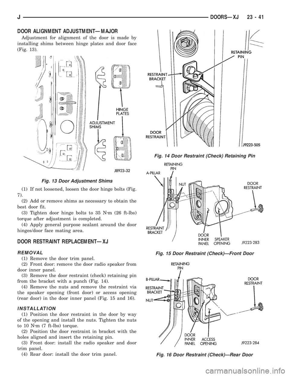
Adjustment for alignment of the door is made by
installing shims between hinge plates and door face
(Fig. 13).
(1) If not loosened, loosen the door hinge bolts (Fig.
7).
(2) Add or remove shims as necessary to obtain the
best door fit.
(3) Tighten door hinge bolts to 35 Nzm (26 ft-lbs)
torque after adjustment is completed.
(4) Apply general purpose sealant around the door
hinges/door face mating area.
DOOR RESTRAINT REPLACEMENTÐXJ
REMOVAL
(1) Remove the door trim panel.
(2) Front door: remove the door radio speaker from
door inner panel.
(3) Remove the door restraint (check) retaining pin
from the bracket with a punch (Fig. 14).
(4) Remove the nuts and remove the restraint via
the speaker opening (front door) or access opening
(rear door) in the door inner panel (Fig. 15 and 16).
INSTALLATION
(1) Position the door restraint in the door by way
of the opening and install the nuts. Tighten the nuts
to 10 Nzm (7 ft-lbs) torque.
(2) Position the door restraint in bracket with the
holes aligned and insert the retaining pin.
(3) Front door: install the radio speaker and door
trim panel.
(4) Rear door: install the door trim panel.
Fig. 14 Door Restraint (Check) Retaining Pin
Fig. 15 Door Restraint (Check)ÐFront Door
Fig. 16 Door Restraint (Check)ÐRear Door
Fig. 13 Door Adjustment Shims
JDOORSÐXJ 23 - 41
Page 1846 of 2198
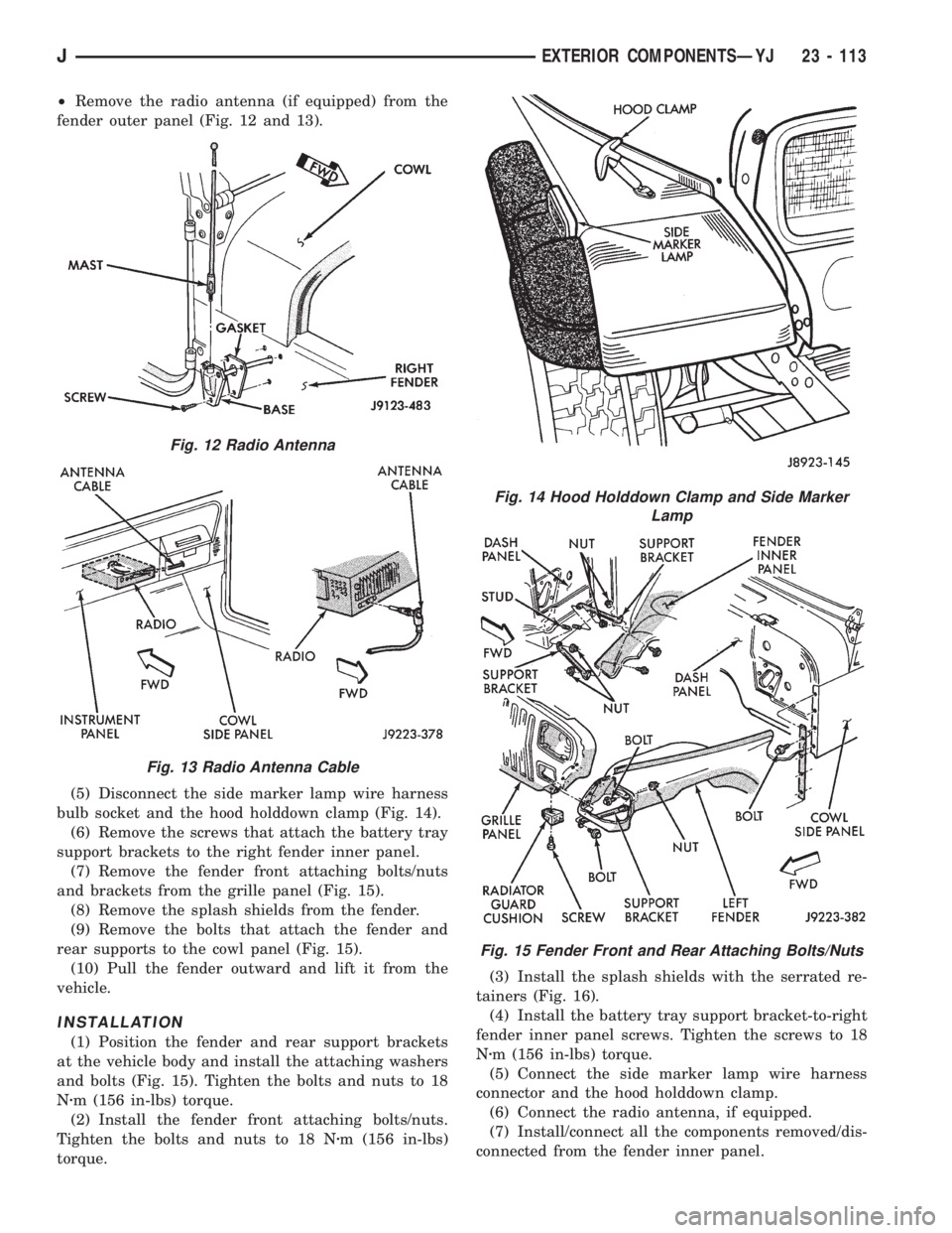
²Remove the radio antenna (if equipped) from the
fender outer panel (Fig. 12 and 13).
(5) Disconnect the side marker lamp wire harness
bulb socket and the hood holddown clamp (Fig. 14).
(6) Remove the screws that attach the battery tray
support brackets to the right fender inner panel.
(7) Remove the fender front attaching bolts/nuts
and brackets from the grille panel (Fig. 15).
(8) Remove the splash shields from the fender.
(9) Remove the bolts that attach the fender and
rear supports to the cowl panel (Fig. 15).
(10) Pull the fender outward and lift it from the
vehicle.
INSTALLATION
(1) Position the fender and rear support brackets
at the vehicle body and install the attaching washers
and bolts (Fig. 15). Tighten the bolts and nuts to 18
Nzm (156 in-lbs) torque.
(2) Install the fender front attaching bolts/nuts.
Tighten the bolts and nuts to 18 Nzm (156 in-lbs)
torque.(3) Install the splash shields with the serrated re-
tainers (Fig. 16).
(4) Install the battery tray support bracket-to-right
fender inner panel screws. Tighten the screws to 18
Nzm (156 in-lbs) torque.
(5) Connect the side marker lamp wire harness
connector and the hood holddown clamp.
(6) Connect the radio antenna, if equipped.
(7) Install/connect all the components removed/dis-
connected from the fender inner panel.
Fig. 12 Radio Antenna
Fig. 13 Radio Antenna Cable
Fig. 14 Hood Holddown Clamp and Side Marker
Lamp
Fig. 15 Fender Front and Rear Attaching Bolts/Nuts
JEXTERIOR COMPONENTSÐYJ 23 - 113
Page 1884 of 2198
INTERIOR COMPONENTS
INDEX
page page
Add-A-TrunkÐYJ........................ 157
Bucket SeatsÐYJ........................ 153
CarpetÐYJ............................. 156
Floor ConsolesÐYJ...................... 155
Front Shoulder BeltsÐYJ.................. 154
Glove BoxÐYJ.......................... 152
Instrument Cluster and Gauge HousingsÐYJ.... 151Instrument Cluster BezelÐYJ............... 151
Instrument Panel ComponentsÐYJ........... 152
Instrument PanelÐYJ..................... 151
Rear Bench SeatÐYJ..................... 153
Rear Shoulder BeltsÐYJ................... 154
SeatsÐYJ............................. 153
SunvisorsÐYJ.......................... 155
INSTRUMENT PANELÐYJ
The instrument panel is constructed of sheet metal
and is attached to cowl panel with screws. The in-
strument panel and defroster grille pad is attached
to the instrument panel with screws.
INSTRUMENT CLUSTER AND GAUGE HOUSINGSÐ
YJ
REMOVAL
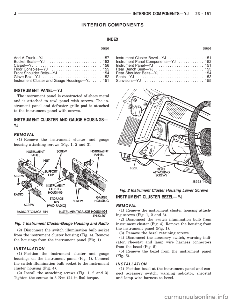
(1) Remove the instrument cluster and gauge
housing attaching screws (Fig. 1, 2 and 3).
(2) Disconnect the switch illumination bulb socket
from the instrument cluster housing (Fig. 4). Remove
the housings from the instrument panel (Fig. 1).
INSTALLATION
(1) Position the instrument cluster and gauge
housings on the instrument panel (Fig. 1). Connect
the switch illumination bulb socket to the instrument
cluster housing (Fig. 4).
(2) Install the attaching screws (Fig. 1, 2 and 3).
Tighten the screws to 3 Nzm (24 in-lbs) torque.
INSTRUMENT CLUSTER BEZELÐYJ
REMOVAL
(1) Remove the instrument cluster housing attach-
ing screws (Fig. 1, 2 and 3).
(2) Disconnect the switch illumination bulb from
instrument cluster (Fig. 4). Remove the housing from
the instrument panel (Fig. 1).
(3) Remove the bezel retaining screws.
(4) Disconnect the accessory switch, warning indi-
cator, rheostat and lamp wire harness connectors
from the bezel (Fig. 5).
(5) Remove the bezel from the instrument panel
(Fig. 6).
INSTALLATION
(1) Position bezel at the instrument panel and con-
nect accessory switch, warning indicator, rheostat
and lamp wire harness to bezel.
Fig. 1 Instrument Cluster/Gauge Housing and Radio
Fig. 2 Instrument Cluster Housing Lower Screws
JINTERIOR COMPONENTSÐYJ 23 - 151
Page 1918 of 2198
COMPONENT SERVICEÐXJ VEHICLES
INDEX
page page
A/C Recirculating Door Vacuum Motor
Replacement........................... 27
Blower Motor Resistors Replacement.......... 31
Blower Motor/Fan Replacement............... 24
Condenser Filter DrierÐ2.5L Engines.......... 27
CondenserÐ4.0L Engines................... 28
Description.............................. 23
Evaporator Coil........................... 30
Evaporator/Blower Housing.................. 29Expansion Valve.......................... 31
Filter DrierÐ4.0L Engines................... 28
Fin Sensing Cycling Clutch Switch............. 31
Heater and A/C Control Replacement.......... 23
Heater Core............................. 26
Heater Housing Replacement................ 26
Heater/Defroster/Instrument Panel Outlet Vacuum
Motor Replacement...................... 26
DESCRIPTION
The Climate Control System combines air condi-
tioning, heating and ventilating capabilities for vehi-
cles equipped with air conditioning. Vehicles without
air conditioning perform heating and ventilating
functions without the air conditioning evaporator.
Both systems consist basically of 2 parts:
²Blower and Air Inlet Assembly
²Heater Core and Air Distribution Assembly
These unit may be removed separately from under
the instrument panel for service.
HEATER AND A/C CONTROL REPLACEMENT
(1) Disconnect negative cable from battery.
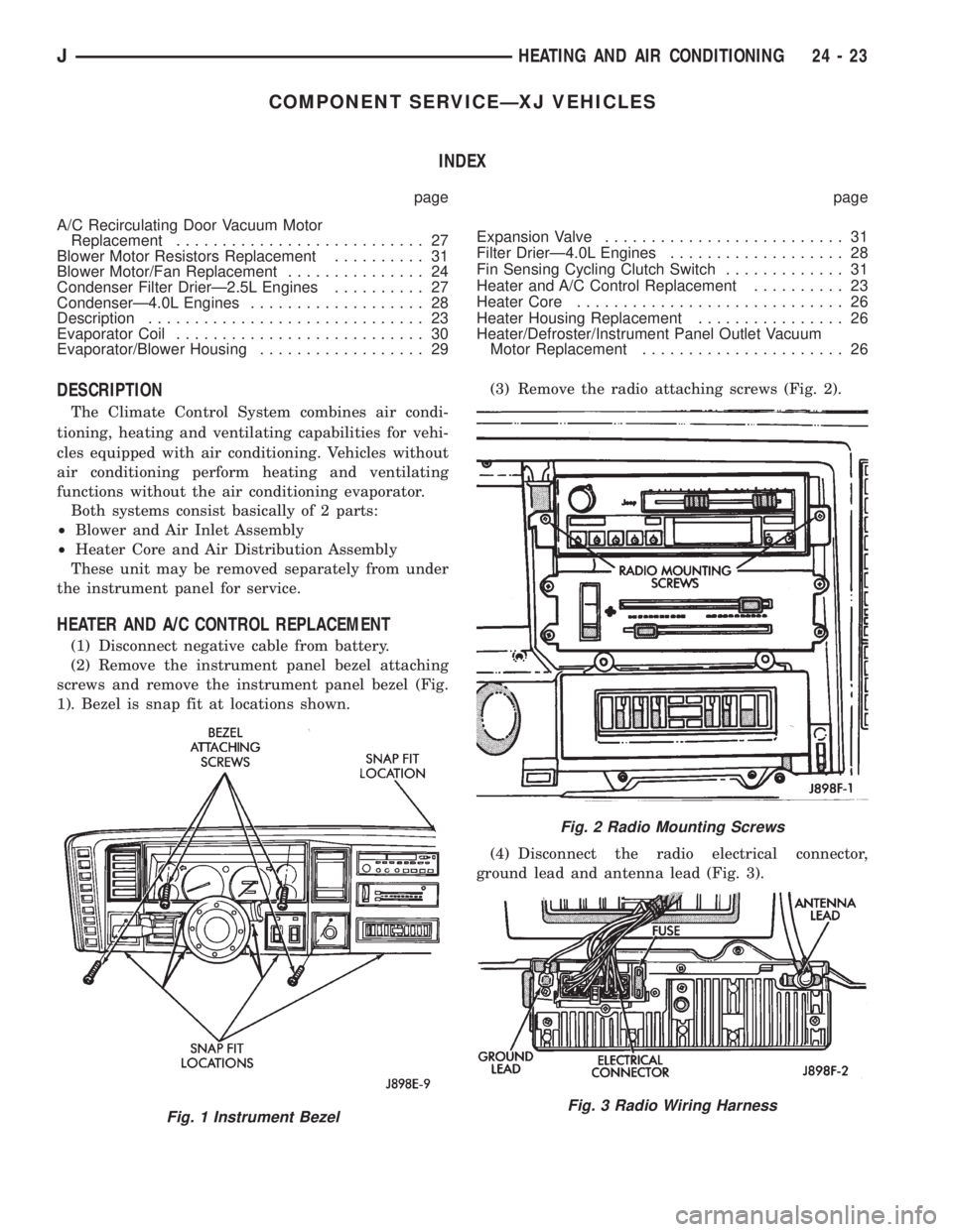
(2) Remove the instrument panel bezel attaching
screws and remove the instrument panel bezel (Fig.
1). Bezel is snap fit at locations shown.(3) Remove the radio attaching screws (Fig. 2).
(4) Disconnect the radio electrical connector,
ground lead and antenna lead (Fig. 3).
Fig. 1 Instrument Bezel
Fig. 2 Radio Mounting Screws
Fig. 3 Radio Wiring Harness
JHEATING AND AIR CONDITIONING 24 - 23
Page 1962 of 2198
- XJ, ANTENNA REMOVE/INSTALL........8F-8
- XJ, GENERAL INFORMATION...........8K-1
- XJ, MULTI-FUNCTION SWITCH..........8J-4
- XJ, MULTI-FUNCTION SWITCH
REMOVE/INSTALL.....................8J-5
- XJ, RADIO REMOVE/INSTALL...........8F-6
- XJ, SOUND BAR REMOVE/INSTALL......8F-8
- XJ, SPEAKERS REMOVE/INSTALL........8F-6
- XJ, TURN SIGNAL/HAZARD WARNING
SYSTEM.............................8J-3
- YJ, ANTENNA REMOVE/INSTALL.......8F-10
- YJ, BUZZER MODULE SCHEMATIC......8U-4
- YJ, GENERAL INFORMATION..........8K-10
- YJ, HAZARD WARNING SYSTEM........8J-4
- YJ, RADIO REMOVE/INSTALL...........8F-9
- YJ, SERVICE PROCEDURES...........8K-17
- YJ, SOUND BAR REMOVE/INSTALL.....8F-10
- YJ, SPEAKERS REMOVE/INSTALL........8F-9
- YJ, TURN SIGNAL SYSTEM............8J-3
- YJ, TURN SIGNAL/HAZARD WARNING
SWITCH REMOVE/INSTALL..............8J-5
30RH/32RH AUTOMATIC TRANSMISSION . . 21-67
30RH/32RH GENERAL SPECIFICATIONS . . 21-335
30RH/32RH IN-VEHICLE SERVICE........21-99
30RH/32RH PRESSURE TEST
SPECIFICATIONS....................21-336
30RH/32RH TORQUE SPECIFICATIONS . . . 21-336
30RH/32RH TRANSMISSION DIAGNOSIS . . 21-70
30RH/32RH TRANSMISSION OVERHAUL . 21-119
30RH/32RH TRANSMISSION REMOVAL
AND INSTALLATION..................21-115
4-CYLINDER ENGINE, ENGINE FIRING
ORDERÐ2.5L.......................8D-32
60-WAY CONNECTOR, POWERTRAIN
CONTROL MODULE (PCM).............14-40
6-CYLINDER ENGINE, AUXILIARY
ELECTRIC COOLING FANÐXJ MODELS
WITH 4.0L...........................7-35
6-CYLINDER ENGINE, ENGINE FIRING
ORDERÐ4.0L.......................8D-32
ABS BRAKE DIAGNOSIS.................5-3
ABS COMPONENT SERVICEABILITY.......5-37
ABS DIAGNOSTIC CONNECTOR.......5-35,5-3
ABS OPERATION AND SERVICE..........5-33
ABS POWER RELAY; ANTI-LOCK BRAKES
(XJ).............................8W-32-1
ABS POWER RELAY; ANTI-LOCK BRAKES
(XJ-RHD).........................8W-32-1
ABS POWER RELAY; ANTI-LOCK BRAKES
(YJ).............................8W-32-1
ABS PUMP MOTOR RELAY; ANTI-LOCK
BRAKES (XJ)......................8W-32-1
ABS PUMP MOTOR RELAY; ANTI-LOCK
BRAKES (XJ-RHD).................8W-32-1
ABS PUMP MOTOR RELAY; ANTI-LOCK
BRAKES (YJ)......................8W-32-1
ABS SYSTEM POWER-UP AND
INITIALIZATION.......................5-35
ABS WARNING LAMP; ANTI-LOCK
BRAKES (XJ)......................8W-32-2
ABS WARNING LAMP; ANTI-LOCK
BRAKES (XJ-RHD).................8W-32-2
ABS WARNING LAMP; ANTI-LOCK
BRAKES (YJ)
......................8W-32-2
ABS WARNING LAMP; INSTRUMENT
CLUSTER (XJ)
.....................8W-40-2
ABS WARNING LAMP; INSTRUMENT
CLUSTER (XJ-RHD)
................8W-40-2
ABS WARNING LAMP; INSTRUMENT
CLUSTER (YJ)
.....................8W-40-2
ABS WARNING LIGHT DISPLAY
...........5-3
ABSOLUTE PRESSURE (MAP) SENSOR,
MANIFOLD; FUEL SYSTEM
.............14-63
ABSOLUTE PRESSURE (MAP) SENSOR,
MANIFOLD; FUEL/IGNITION (YJ)
......8W-30-4
ABSOLUTE PRESSURE (MAP) SENSOR,
MANIFOLD; IGNITION SYSTEMS
....8D-23,8D-5
ABSOLUTE PRESSURE (MAP) SENSOR
TEST, MANIFOLD; FUEL SYSTEM
........14-47
ABSOLUTE PRESSURE (MAP) SENSOR
TEST, MANIFOLD; IGNITION SYSTEMS
....8D-11
ABSOLUTE PRESSURE (MAP)
SENSORÐPCM INPUT, MANIFOLD
.......14-23
ABSOLUTE PRESSURE SENSOR,
MANIFOLD; FUEL/IGNITION (XJ)
......8W-30-4
ABSOLUTE PRESSURE SENSOR,
MANIFOLD; FUEL/IGNITION (XJ-RHD)
. . 8W-30-4ABSORBER, SHOCK; FRONT
SUSPENSION AND AXLE............2-13,2-16
ABSORBER, SHOCK; REAR SUSPENSION
AND AXLES........................3-4,3-7
A/C BLOWER MOTOR.................24-35
A/C COMPONENTS....................24-4
A/C COMPRESSOR; AIR CONDITIONING/
HEATER (YJ)......................8W-42-2
A/C COMPRESSOR CLUTCH............24-15
A/C COMPRESSOR CLUTCH RELAY . 24-15,24-16
A/C CONDENSER.....................24-34
A/C CONTROL REPLACEMENT, HEATER . . . 24-23
A/C OPERATION, HEATER...............24-1
A/C RECIRCULATING DOOR VACUUM
MOTOR REPLACEMENT...............24-27
ACCELERATION SWITCH; ANTI-LOCK
BRAKES (XJ)......................8W-32-1
ACCELERATION SWITCH; ANTI-LOCK
BRAKES (XJ-RHD).................8W-32-1
ACCELERATION SWITCH; ANTI-LOCK
BRAKES (YJ)......................8W-32-1
ACCELERATION SWITCH; BRAKES........5-35
ACCELERATION SWITCH INSTALLATION....5-39
ACCELERATION SWITCH OPERATION......5-37
ACCELERATION SWITCH REMOVAL.......5-39
ACCELERATOR PEDAL.................14-17
ACCELERATOR PEDAL AND THROTTLE
CABLE........................14-17,14-58
ACCESSORY DRIVE BELT...............0-21
ACCESSORY DRIVE BELTS, ENGINE.......7-38
ACCESSORY LAMP AND HEATER
CONTROL PANEL LAMP; INTERIOR
LIGHTING (YJ)....................8W-44-1
ACCUMULATOR PISTONS AND SPRINGS . 21-189
A/C-HEATER BLOWER MOTOR; AIR
CONDITIONING/HEATER (YJ).........8W-42-2
A/C-HEATER SYSTEM; AIR
CONDITIONING/HEATER (XJ).........8W-42-1
A/C-HEATER SYSTEM; AIR
CONDITIONING/HEATER (XJ-RHD).....8W-42-1
ADD-A-TRUNKÐYJ..................23-157
ADJUSTER/MOTORS, POWER SEAT . . . 8R-1,8R-2
ADJUSTER/MOTORS REMOVE/INSTALL,
POWER SEAT........................8R-3
ADJUSTMENT, BRAKELIGHT SWITCH......5-32
ADJUSTMENT, COMPASS VARIATION......8C-5
ADJUSTMENT, DIFFERENTIAL SHIM
PACK MEASUREMENT..................2-43
ADJUSTMENT, DRUM BRAKE............5-57
ADJUSTMENT, FRONT BAND...........21-102
ADJUSTMENT, GEARSHIFT CABLE/
LINKAGE...........................21-71
ADJUSTMENT, PARK INTERLOCK CABLE . 21-195
ADJUSTMENT PROCEDURES,
TRANSMISSION ASSEMBLY...........21-155
ADJUSTMENT, REAR WHEEL SENSOR
INSTALLATION........................5-38
ADJUSTMENT, SHIFT CABLE...........21-195
ADJUSTMENT, SHIFT LINKAGE . . . 21-286,21-309
ADJUSTMENT, TRANSMISSION
THROTTLE CABLE...................21-194
ADJUSTMENT, TRANSMISSION
THROTTLE VALVE CABLE..............21-71
ADJUSTMENT, VALVE BODY ASSEMBLY . . 21-153
ADJUSTMENT (XJ), PARK INTERLOCK
CABLE............................21-101
ADJUSTMENT (XJ), SHIFT CABLE.......21-100
ADJUSTMENT (XJ/YJ), PARKING BRAKE
CABLE TENSIONER....................5-69
ADJUSTMENT (XJ/YJ), THROTTLE VALVE
CABLE............................21-101
ADJUSTMENT (YJ), SHIFT LINKAGE.....21-100
ADJUSTMENTÐMAJOR, DOOR
ALIGNMENT.........................23-41
ADJUSTMENTÐMINOR, DOOR
ALIGNMENT.........................23-37
ADJUSTMENTÐXJ, DOOR LATCH........23-48
ADJUSTMENTÐXJ, HOOD.............23-10
ADJUSTMENTÐXJ, LIFTGATE...........23-63
ADJUSTMENTÐYJ, TAILGATE..........23-121
ADJUSTMENTS, ALIGNMENT
MEASUREMENTS
......................2-8
ADJUSTMENTS, STEERING GEAR
........19-24
AFTERMARKET PAINT AND TRIM
REPAIR PRODUCTSÐXJ
..............23-159
AFTERMARKET PAINT AND TRIM
REPAIR PRODUCTSÐYJ
..............23-160
AIR CLEANER
.......................14-29AIR CLEANER ELEMENT; EMISSION
CONTROL SYSTEMS...................25-7
AIR CLEANER ELEMENT; FUEL SYSTEM . . . 14-59
AIR CLEANER ELEMENT; LUBRICATION
AND MAINTENANCE...................0-18
AIR CLEANER HOUSING...............14-58
AIR CONDITIONING...................24-37
AIR CONDITIONING (A/C) CLUTCH
RELAY.............................14-58
AIR CONDITIONING (A/C) CLUTCH
RELAYÐPCM OUTPUT................14-26
AIR CONDITIONING (A/C) CONTROLSÐ
PCM INPUT.........................14-21
AIR CONDITIONING CONTROLSÐXJ
VEHICLES..........................24-15
AIR CONDITIONING CONTROLSÐYJ
VEHICLES..........................24-16
AIR CONDITIONING, HEATER; AIR
CONDITIONING/HEATER (YJ).........8W-42-2
AIR CONDITIONING OPERATION; AIR
CONDITIONING/HEATER (XJ).........8W-42-2
AIR CONDITIONING OPERATION; AIR
CONDITIONING/HEATER (XJ-RHD).....8W-42-2
AIR CONDITIONING PERFORMANCE
TESTS.............................24-12
AIR CONDITIONING SCHEMATICÐXJ......24-5
AIR CONDITIONING TEST PROCEDURES,
HEATING...........................24-15
AIR CONTROL (IAC) MOTOR, IDLE; FUEL
SYSTEM............................14-62
AIR CONTROL (IAC) MOTOR, IDLE;
FUEL/IGNITION (XJ)................8W-30-2
AIR CONTROL (IAC) MOTOR, IDLE;
FUEL/IGNITION (YJ)................8W-30-2
AIR CONTROL (IAC) MOTOR, IDLE;
FUEL/IGNITION (XJ-RHD)............8W-30-2
AIR CONTROL (IAC) MOTORÐPCM
OUTPUT, IDLE.......................14-27
AIR CONTROL MOTOR TEST, IDLE.......14-49
AIR DEFLECTORÐXJ, COWL
WEATHERSTRIP SEAL/CROSSMEMBER . . . 23-11
AIR DOOR VACUUM MOTOR, FRESH.....24-34
AIR EXHAUST GRILLEÐXJ.............23-25
AIR GAP, SPEED SENSOR...............5-37
AIR INTAKE DUCT, FRESH..............24-34
AIR PRESSURE TEST.................21-74
AIR TEMPERATURE SENSOR, INTAKE;
FUEL/IGNITION (XJ)................8W-30-4
AIR TEMPERATURE SENSOR, INTAKE;
FUEL/IGNITION (YJ)................8W-30-4
AIR TEMPERATURE SENSOR, INTAKE;
FUEL/IGNITION (XJ-RHD)............8W-30-4
AIR TEMPERATURE SENSOR, INTAKE
MANIFOLD; FUEL SYSTEM.............14-60
AIR TEMPERATURE SENSOR, INTAKE
MANIFOLD; IGNITION SYSTEMS....8D-23,8D-5
AIR TEMPERATURE, SENSOR
RESISTANCE (OHMS)ÐCOOLANT
TEMPERATURE SENSOR/MANIFOLD......14-46
AIR TEMPERATURE SENSOR TEST,
INTAKE MANIFOLD; FUEL SYSTEM.......14-46
AIR TEMPERATURE SENSOR TEST,
INTAKE MANIFOLD; IGNITION
SYSTEMS..........................8D-11
AIR TEMPERATURE SENSORÐPCM
INPUT, INTAKE MANIFOLD.............14-22
AIRBAG MODULE.....................8M-1
AIRBAG MODULE HANDLING............8M-2
AIRBAG MODULE REMOVE/INSTALL......8M-3
AIRBAG MODULE REMOVEÐINSTALL....19-49
AIRBAG SYSTEM; RESTRAINT SYSTEMS . . 8M-1
AIRBAG SYSTEM; STEERING...........19-47
AIRBAG SYSTEM SERVICE (DEPLOYED) . . . 8M-2
AIR-CONDITIONER COMPRESSOR........0-21
ALIGNMENT ADJUSTMENTÐMAJOR,
DOOR.............................23-41
ALIGNMENT ADJUSTMENTÐMINOR,
DOOR.............................23-37
ALIGNMENT, FRONT WHEEL..............2-5
ALIGNMENTÐXJ, HEADLAMP...........8L-6
ALIGNMENTÐYJ, HEADLAMP
..........8L-22
ALIGNMENTÐYJ, HOOD
..............23-107
ANCHOR AND BUMPERÐXJ, LIFTGATE
LICENSE PLATE SCREW
...............23-65
ANGLE, GROUND CLEARANCE AND
RAMP
..............................0-11
ANGLE MEASUREMENT, UNIVERSAL
JOINT
..............................16-4
JINDEX 1
Description Group-Page Description Group-Page Description Group-Page