1995 JEEP CHEROKEE lock
[x] Cancel search: lockPage 124 of 2198
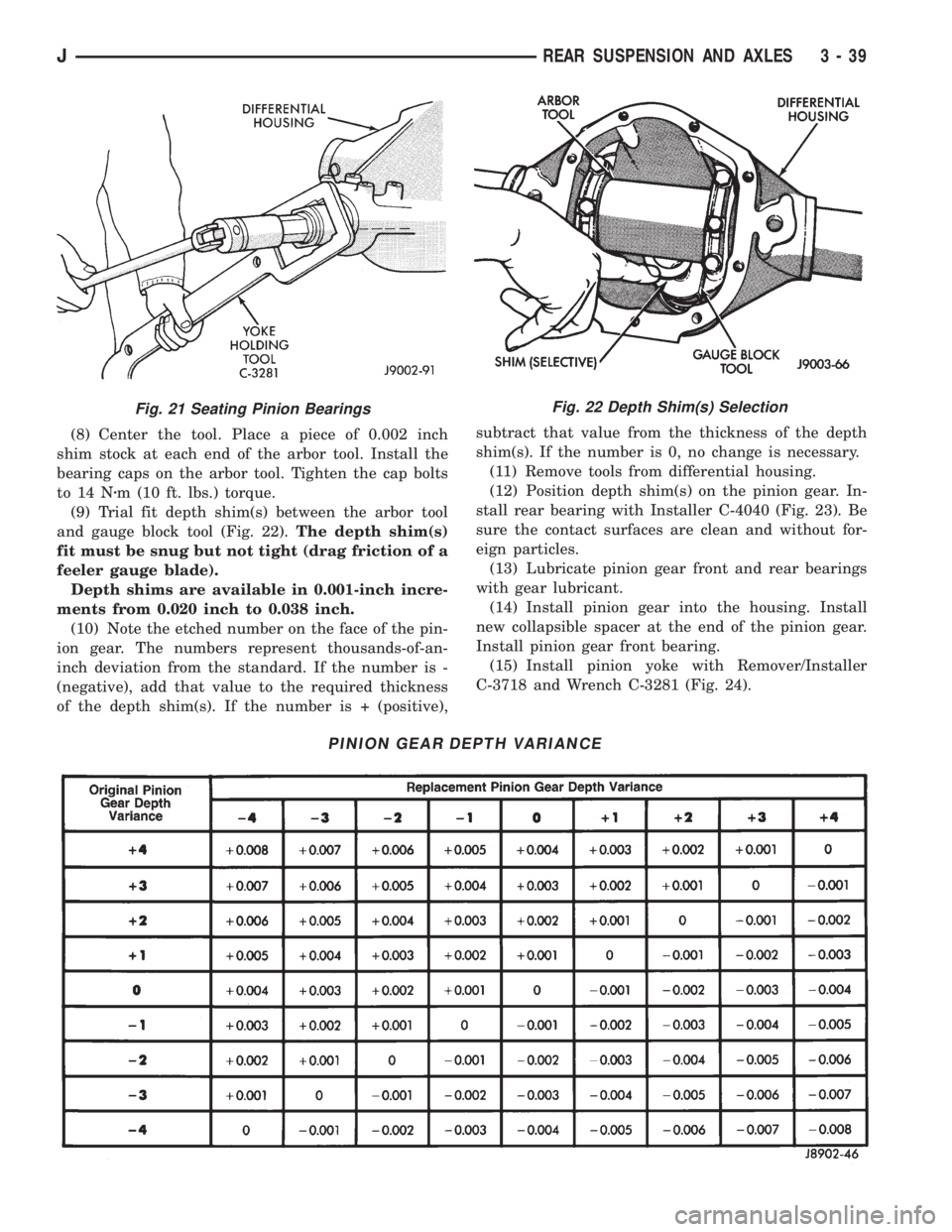
(8) Center the tool. Place a piece of 0.002 inch
shim stock at each end of the arbor tool. Install the
bearing caps on the arbor tool. Tighten the cap bolts
to 14 Nzm (10 ft. lbs.) torque.
(9) Trial fit depth shim(s) between the arbor tool
and gauge block tool (Fig. 22).The depth shim(s)
fit must be snug but not tight (drag friction of a
feeler gauge blade).
Depth shims are available in 0.001-inch incre-
ments from 0.020 inch to 0.038 inch.
(10) Note the etched number on the face of the pin-
ion gear. The numbers represent thousands-of-an-
inch deviation from the standard. If the number is -
(negative), add that value to the required thickness
of the depth shim(s). If the number is + (positive),subtract that value from the thickness of the depth
shim(s). If the number is 0, no change is necessary.
(11) Remove tools from differential housing.
(12) Position depth shim(s) on the pinion gear. In-
stall rear bearing with Installer C-4040 (Fig. 23). Be
sure the contact surfaces are clean and without for-
eign particles.
(13) Lubricate pinion gear front and rear bearings
with gear lubricant.
(14) Install pinion gear into the housing. Install
new collapsible spacer at the end of the pinion gear.
Install pinion gear front bearing.
(15) Install pinion yoke with Remover/Installer
C-3718 and Wrench C-3281 (Fig. 24).
Fig. 22 Depth Shim(s) Selection
PINION GEAR DEPTH VARIANCE
Fig. 21 Seating Pinion Bearings
JREAR SUSPENSION AND AXLES 3 - 39
Page 127 of 2198
ring and pinion gear. Seat the bearing cups with the
procedure described above.
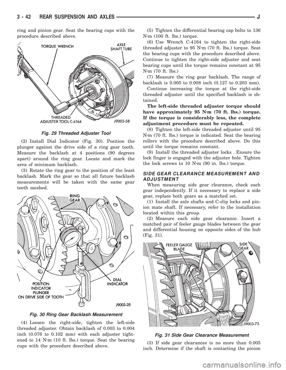
(2) Install Dial Indicator (Fig. 30). Position the
plunger against the drive side of a ring gear tooth.
Measure the backlash at 4 positions (90 degrees
apart) around the ring gear. Locate and mark the
area of minimum backlash.
(3) Rotate the ring gear to the position of the least
backlash. Mark the gear so that all future backlash
measurements will be taken with the same gear
teeth meshed.
(4) Loosen the right-side, tighten the left-side
threaded adjuster. Obtain backlash of 0.003 to 0.004
inch (0.076 to 0.102 mm) with each adjuster tight-
ened to 14 Nzm (10 ft. lbs.) torque. Seat the bearing
cups with the procedure described above.(5) Tighten the differential bearing cap bolts to 136
Nzm (100 ft. lbs.) torque.
(6) Use Wrench C-4164 to tighten the right-side
threaded adjuster to 95 Nzm (70 ft. lbs.) torque. Seat
the bearing cups with the procedure described above.
Continue to tighten the right-side adjuster and seat
bearing cups until the torque remains constant at 95
Nzm (70 ft. lbs.)
(7) Measure the ring gear backlash. The range of
backlash is 0.005 to 0.008 inch (0.127 to 0.203 mm).
Continue increasing the torque at the right-side
threaded adjuster until the specified backlash is ob-
tained.
The left-side threaded adjuster torque should
have approximately 95 Nzm (70 ft. lbs.) torque.
If the torque is considerably less, the complete
adjustment procedure must be repeated.
(8) Tighten the left-side threaded adjuster until 95
Nzm (70 ft. lbs.) torque is indicated. Seat the bearing
rollers with the procedure described above. Do this
until the torque remains constant.
(9) Install the threaded adjuster locks . Ensure the
lock finger is engaged with the adjuster hole. Tighten
the lock screws to 10 Nzm (90 in. lbs.) torque.
SIDE GEAR CLEARANCE MEASUREMENT AND
ADJUSTMENT
When measuring side gear clearance, check each
gear independently. If it necessary to replace a side
gear, replace both gears as a matched set.
(1) Install the axle shafts and C-clip locks and pin-
ion mate shaft. If necessary, refer to the installation
located within this group.
(2) Measure each side gear clearance. Insert a
matched pair of feeler gauge blades between the gear
and differential housing on opposite sides of the hub
(Fig. 31).
(3) If side gear clearances is no more than 0.005
inch. Determine if the shaft is contacting the pinion
Fig. 29 Threaded Adjuster Tool
Fig. 30 Ring Gear Backlash Measurement
Fig. 31 Side Gear Clearance Measurement
3 - 42 REAR SUSPENSION AND AXLESJ
Page 128 of 2198
gear mate shaft.Do not remove the feeler
gauges, inspect the axle shaft with the feeler
gauge inserted behind the side gear.If the end of
the axle shaft is not contacting the pinion gear mate
shaft, the side gear clearance is acceptable.
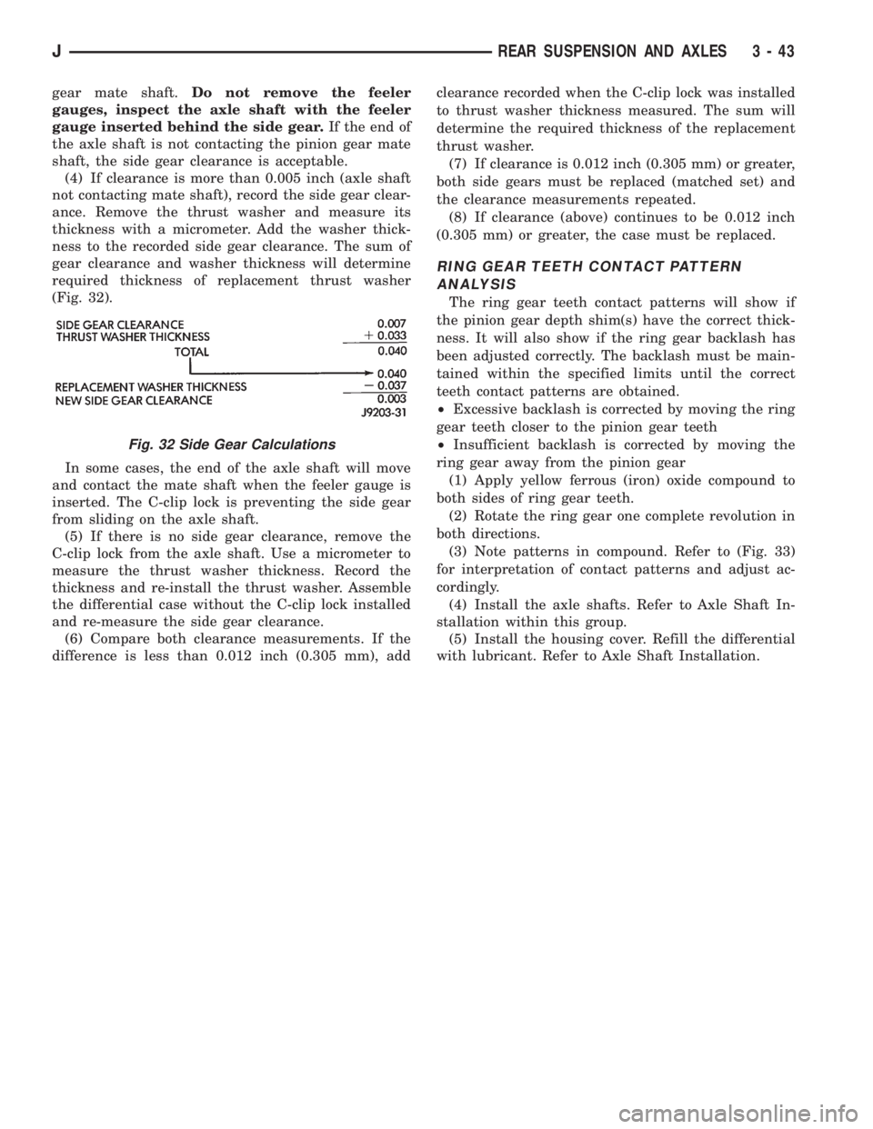
(4) If clearance is more than 0.005 inch (axle shaft
not contacting mate shaft), record the side gear clear-
ance. Remove the thrust washer and measure its
thickness with a micrometer. Add the washer thick-
ness to the recorded side gear clearance. The sum of
gear clearance and washer thickness will determine
required thickness of replacement thrust washer
(Fig. 32).
In some cases, the end of the axle shaft will move
and contact the mate shaft when the feeler gauge is
inserted. The C-clip lock is preventing the side gear
from sliding on the axle shaft.
(5) If there is no side gear clearance, remove the
C-clip lock from the axle shaft. Use a micrometer to
measure the thrust washer thickness. Record the
thickness and re-install the thrust washer. Assemble
the differential case without the C-clip lock installed
and re-measure the side gear clearance.
(6) Compare both clearance measurements. If the
difference is less than 0.012 inch (0.305 mm), addclearance recorded when the C-clip lock was installed
to thrust washer thickness measured. The sum will
determine the required thickness of the replacement
thrust washer.
(7) If clearance is 0.012 inch (0.305 mm) or greater,
both side gears must be replaced (matched set) and
the clearance measurements repeated.
(8) If clearance (above) continues to be 0.012 inch
(0.305 mm) or greater, the case must be replaced.
RING GEAR TEETH CONTACT PATTERN
ANALYSIS
The ring gear teeth contact patterns will show if
the pinion gear depth shim(s) have the correct thick-
ness. It will also show if the ring gear backlash has
been adjusted correctly. The backlash must be main-
tained within the specified limits until the correct
teeth contact patterns are obtained.
²Excessive backlash is corrected by moving the ring
gear teeth closer to the pinion gear teeth
²Insufficient backlash is corrected by moving the
ring gear away from the pinion gear
(1) Apply yellow ferrous (iron) oxide compound to
both sides of ring gear teeth.
(2) Rotate the ring gear one complete revolution in
both directions.
(3) Note patterns in compound. Refer to (Fig. 33)
for interpretation of contact patterns and adjust ac-
cordingly.
(4) Install the axle shafts. Refer to Axle Shaft In-
stallation within this group.
(5) Install the housing cover. Refill the differential
with lubricant. Refer to Axle Shaft Installation.
Fig. 32 Side Gear Calculations
JREAR SUSPENSION AND AXLES 3 - 43
Page 130 of 2198
TRAC-LOK DIFFERENTIAL
OPERATION
In a conventional differential, the torque applied to
the ring gear is transmitted to the axle shafts through
the differential gears. During normal operation, the
torque transmitted to each wheel is equal at all times.
However, if one wheel spins, the opposite wheel will
generate only as much torque as the spinning wheel.
In the Trac-Lok differential, part of the ring gear
torque is transmitted through clutch packs. The clutch
packs contain multiple disc. The clutch will have radial
grooves on the plates, and concentric grooves on the
discs or bonded fiber material which is smooth.
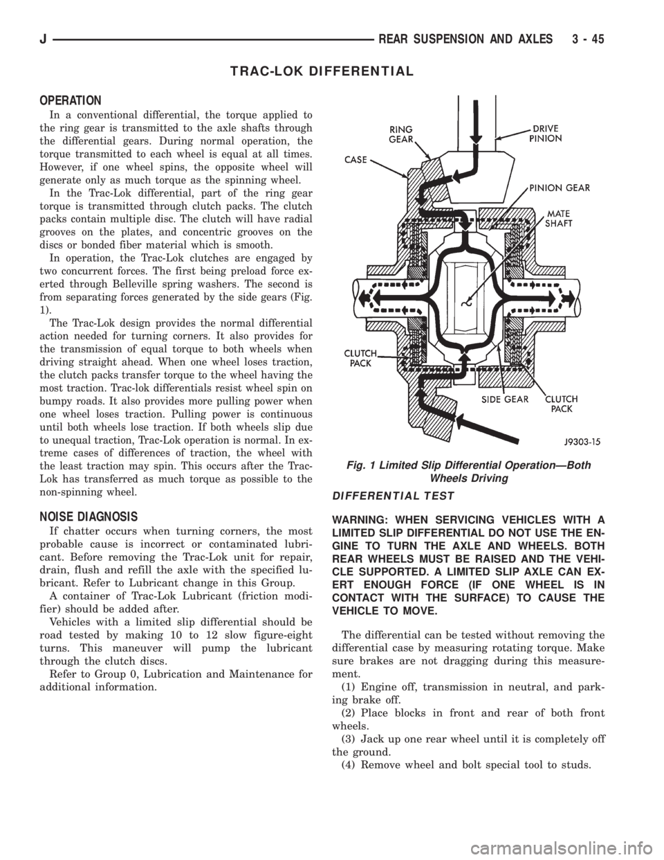
In operation, the Trac-Lok clutches are engaged by
two concurrent forces. The first being preload force ex-
erted through Belleville spring washers. The second is
from separating forces generated by the side gears (Fig.
1).
The Trac-Lok design provides the normal differential
action needed for turning corners. It also provides for
the transmission of equal torque to both wheels when
driving straight ahead. When one wheel loses traction,
the clutch packs transfer torque to the wheel having the
most traction. Trac-lok differentials resist wheel spin on
bumpy roads. It also provides more pulling power when
one wheel loses traction. Pulling power is continuous
until both wheels lose traction. If both wheels slip due
to unequal traction, Trac-Lok operation is normal. In ex-
treme cases of differences of traction, the wheel with
the least traction may spin. This occurs after the Trac-
Lok has transferred as much torque as possible to the
non-spinning wheel.
NOISE DIAGNOSIS
If chatter occurs when turning corners, the most
probable cause is incorrect or contaminated lubri-
cant. Before removing the Trac-Lok unit for repair,
drain, flush and refill the axle with the specified lu-
bricant. Refer to Lubricant change in this Group.
A container of Trac-Lok Lubricant (friction modi-
fier) should be added after.
Vehicles with a limited slip differential should be
road tested by making 10 to 12 slow figure-eight
turns. This maneuver will pump the lubricant
through the clutch discs.
Refer to Group 0, Lubrication and Maintenance for
additional information.
DIFFERENTIAL TEST
WARNING: WHEN SERVICING VEHICLES WITH A
LIMITED SLIP DIFFERENTIAL DO NOT USE THE EN-
GINE TO TURN THE AXLE AND WHEELS. BOTH
REAR WHEELS MUST BE RAISED AND THE VEHI-
CLE SUPPORTED. A LIMITED SLIP AXLE CAN EX-
ERT ENOUGH FORCE (IF ONE WHEEL IS IN
CONTACT WITH THE SURFACE) TO CAUSE THE
VEHICLE TO MOVE.
The differential can be tested without removing the
differential case by measuring rotating torque. Make
sure brakes are not dragging during this measure-
ment.
(1) Engine off, transmission in neutral, and park-
ing brake off.
(2) Place blocks in front and rear of both front
wheels.
(3) Jack up one rear wheel until it is completely off
the ground.
(4) Remove wheel and bolt special tool to studs.
Fig. 1 Limited Slip Differential OperationÐBoth
Wheels Driving
JREAR SUSPENSION AND AXLES 3 - 45
Page 132 of 2198
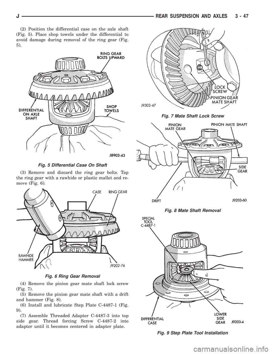
(2) Position the differential case on the axle shaft
(Fig. 5). Place shop towels under the differential to
avoid damage during removal of the ring gear (Fig.
5).
(3) Remove and discard the ring gear bolts. Tap
the ring gear with a rawhide or plastic mallet and re-
move (Fig. 6).
(4) Remove the pinion gear mate shaft lock screw
(Fig. 7).
(5) Remove the pinion gear mate shaft with a drift
and hammer (Fig. 8).
(6) Install and lubricate Step Plate C-4487-1 (Fig.
9).
(7) Assemble Threaded Adapter C-4487-3 into top
side gear. Thread forcing Screw C-4487-2 into
adapter until it becomes centered in adapter plate.
Fig. 7 Mate Shaft Lock Screw
Fig. 8 Mate Shaft Removal
Fig. 9 Step Plate Tool Installation
Fig. 5 Differential Case On Shaft
Fig. 6 Ring Gear Removal
JREAR SUSPENSION AND AXLES 3 - 47
Page 134 of 2198
(2) Inspect clutch pack plates for wear, scoring or
damage. Replace both clutch packs if any one compo-
nent in either pack is damaged.
(3) Inspect side and pinion gears. Replace any gear
that is worn, cracked, chipped or damaged.
(4) Inspect differential case and pinion shaft. Re-
place if worn or damaged.
PRESOAK PLATES AND DISC
Plates and dics with fiber coating (no groves or
lines) must be presoaked in Friction Modifier before
assembly. Soak plates and discs for a minimum of 20
minutes. Add remaining Friction Modifier to differen-
tial after assembly.
ASSEMBLY
(1) The clutch discs are replaceable as complete
sets only. If one clutch disc pack is damaged, both
packs must be replaced. Lubricate each component
with gear lubricant before assembly and installation.
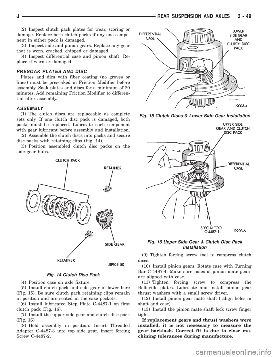
(2) Assemble the clutch discs into packs and secure
disc packs with retaining clips (Fig. 14).
(3) Position assembled clutch disc packs on the
side gear hubs.
(4) Position case on axle fixture.
(5) Install clutch pack and side gear in lower bore
(Fig. 15). Be sure clutch pack retaining clips remain
in position and are seated in the case pockets.
(6) Install lubricated Step Plate C-4487-1 on first
clutch pack (Fig. 16).
(7) Install the upper side gear and clutch disc pack
(Fig. 16).
(8) Hold assembly in position. Insert Threaded
Adapter C-4487-3 into top side gear, insert forcing
Screw C-4487-2.(9) Tighten forcing screw tool to compress clutch
discs.
(10) Install pinion gears. Rotate case with Turning
Bar C-4487-4. Make sure holes of pinion mate gears
are aligned with case.
(11) Tighten forcing screw to compress the
Belleville plates. Lubricate and install pinion gear
thrust washers with a small screw driver.
(12) Install pinion gear mate shaft ( align holes in
shaft and case).
(13) Install the pinion mate shaft lock screw finger
tight.
If replacement gears and thrust washers were
installed, it is not necessary to measure the
gear backlash. Correct fit is due to close ma-
chining tolerances during manufacture.
Fig. 14 Clutch Disc Pack
Fig. 15 Clutch Discs & Lower Side Gear Installation
Fig. 16 Upper Side Gear & Clutch Disc Pack
Installation
JREAR SUSPENSION AND AXLES 3 - 49
Page 138 of 2198
BRAKES
CONTENTS
page page
ABS BRAKE DIAGNOSIS................... 3
ABS OPERATION AND SERVICE............ 33
BRAKE FLUIDÐBRAKE BLEEDINGÐ
BRAKELINES AND HOSES............... 10
DISC BRAKES.......................... 45
DRUM BRAKES......................... 55
GENERAL INFORMATION.................. 1MASTER CYLINDERÐCOMBINATION VALVE . . 15
PARKING BRAKES....................... 60
POWER BRAKE BOOSTERÐBRAKE PEDALÐ
BRAKELIGHT SWITCH.................. 22
SERVICE BRAKE DIAGNOSIS............... 4
SPECIFICATIONS........................ 70
GENERAL INFORMATION
INDEX
page page
Antilock Brakes (ABS)....................... 1
Brake Components......................... 1
Brake Fluid/Lubricants/Cleaning Solvents......... 2
Brake Safety Precautions.................... 2Brake Warning Lights....................... 1
Brakelining Material........................ 1
Jeep Body Code Letters..................... 2
BRAKE COMPONENTS
Power assist front disc and rear drum brakes are
standard on Cherokee/Wrangler models. Disc brake
components consist of single piston calipers and ven-
tilated rotors. Rear drum brakes are dual shoe units
with cast brake drums.
The parking brake mechanism is lever and cable
operated. The cables are attached to levers on the
rear drum brake secondary shoes. The parking
brakes are operated by a foot pedal on YJ models and
a hand lever on XJ models.
A 205 mm dual diaphragm vacuum power brake
booster is used for all applications. Two master cylin-
ders are used; 4-cylinder YJ models have a one-piece
master cylinder. All other models have a two-piece
master cylinder with plastic reservoir.
All models are equipped with a combination valve.
The valve contains a pressure differential valve and
switch and a fixed rate rear proportioning valve.
BRAKELINING MATERIAL
Factory brakelining on all models consists of an or-
ganic base material combined with metallic particles.
The lining does not contain asbestos.
BRAKE WARNING LIGHTS
Cherokee/Wrangler models are equipped with one
or two brake warning lights. A red warning light is
standard on all models. An amber light is added on
models with ABS brakes. Both lights are located in
the instrument panel.
The red light is in circuit with the pressure differ-
ential switch (in the combination valve), and with the
parking brake switch. The light alerts the driver
when the parking brakes are applied, or when a
pressure differential exists between the front and
rear hydraulic systems. The light also illuminates for
a few seconds at start up as part of a bulb check.
The ABS warning light is amber in color and is lo-
cated in the same side of the instrument cluster as
the red warning light. The amber light only illumi-
nates when an ABS circuit fault occurs.
ANTILOCK BRAKES (ABS)
An antilock brake system (ABS) is available on
Cherokee/Wrangler models as an option. The system
is an electronically operated, all-wheel brake control
system. The ABS system is designed to prevent
wheel lockup during periods of high wheel slip brak-
ing. Refer to the antilock brake section for operation
and service information.
JBRAKES 5 - 1
Page 140 of 2198
ABS BRAKE DIAGNOSIS
INDEX
page page
ABS Diagnostic Connector................... 3
ABS Warning Light Display................... 3
Antilock ECU and Hcu Diagnosis............... 3
DRB Scan Tool............................ 3General Information........................ 3
Normal Operating Conditions.................. 3
Wheel/Tire Size and Input Signals.............. 3
GENERAL INFORMATION
The DRB scan tool is required for ABS diagnosis.
The scan tool is used to identify ABS circuit faults.
Once a faulty circuit has been identified, refer to
the appropriate chassis/body diagnostic manual for
individual component testing.
ABS WARNING LIGHT DISPLAY
The amber antilock light illuminates at startup as
part of the system self check feature. The light illu-
minates for 2-3 seconds then goes off as part of the
normal check routine.
An ABS circuit fault is indicated when the amber
light remains on after startup, or illuminates during
vehicle operation.
Verify that a fault is actually related to the ABS
system before making repairs. For example, if the
red warning illuminates but the ABS light does not,
the problem is related to a service brake component
and not the ABS system. Or, if neither light illumi-
nates but a brake problem is noted, again, the prob-
lem is with a service brake component and not with
the ABS system.
ABS DIAGNOSTIC CONNECTOR
The ABS diagnostic connector is inside the vehicle.
The connector is the access point for the DRB scan tool.
On XJ models, the connector is located under the
instrument panel to the right of the steering column.
On some models, the connecter may be tucked under
the carpeting on the transmission tunnel. The con-
necter is a black, 6-way type.
On YJ models, the connector is under the instru-
ment panel by the the driver side kick panel. The
connecter is a black, 6 or 8-way type.
The DRB scan tool kit contains adapter cords for
both types of connecter. Use the appropriate cord for
test hookup.
DRB SCAN TOOL
ABS diagnosis is performed with the DRB scan tool.
Refer to the DRB scan tool manual for test hookup and
procedures. Diagnosis information is provided in the ap-
propriate chassis/body diagnostic manual.
WHEEL/TIRE SIZE AND INPUT SIGNALS
Antilock system operation is dependant on accurate
signals from the wheel speed sensors. Ideally, the ve-
hicle wheels and tires should all be the same size
and type. However, the Jeep ABS system is designed
to operate with a compact spare tire installed.
NORMAL OPERATING CONDITIONS
Sound Levels
The hydraulic control unit pump and solenoid valves
may produce some sound as they cycle on and off. This
is a normal condition and should not be mistaken for
faulty operation. Under most conditions, pump and so-
lenoid valve operating sounds will not be audible.
Vehicle Response In Antilock Mode
During antilock braking, the hydraulic control unit
solenoid valves cycle rapidly in response to antilock
electronic control unit signals.
The driver will experience a pulsing sensation
within the vehicle as the solenoids decrease, hold, or
increase pressure as needed. Brake pedal pulsing will
also be noted and is anormal condition.
Steering Response
A modest amount of steering input is required dur-
ing extremely high deceleration braking, or when
braking on differing traction surfaces. An example of
differing traction surfaces would be when the left
side wheels are on ice and the right side wheels are
on dry pavement.
Owner Induced Faults
Driving away with the parking brakes still applied
will cause warning light illumination. Pumping the
brake pedal will also generate a system fault and in-
terfere with ABS system operation.
ANTILOCK ECU AND HCU DIAGNOSIS
An ECU or HCU fault can only be determined
through testing with the DRB scan tool. Do not re-
place either component unless a fault is actually in-
dicated.
JABS BRAKE DIAGNOSIS 5 - 3