1995 JEEP CHEROKEE key
[x] Cancel search: keyPage 494 of 2198
POWER LOCK MOTOR
(1) Once it is determined which lock motor is inop-
erative, that motor can be tested. Disconnect the wire
connector at the motor. Apply 12 volts to the motor
terminals to check its operation in one direction. Re-
verse the polarity to check the operation in the other
direction. If OK, repair circuits to power lock/unlock
relays as required. If not OK, replace the motor.
(2) If all lock motors are inoperative, the problem
may be caused by one shorted motor. Disconnecting a
shorted motor will allow the good motors to operate.
Disconnect each motor connector, one at a time, and
re-check both lock and unlock functions while operat-
ing the door lock switch. If disconnecting one motor
causes the other motors to become functional, go
back to step 1 to test the disconnected motor.
KEYLESS ENTRY TRANSMITTER
(1) Depress either transmitter button and note
whether red Light-Emitting Diode (LED) on trans-
mitter case lights. If OK, go to next step. If not OK,
replace batteries as described under Keyless Entry
Transmitter in Service Procedures. Test transmitter
operation. If OK, discard faulty batteries. If not OK,
go to next step.
(2) Perform transmitter program procedure with
suspect transmitter and another known good trans-
mitter, as described in Service Procedures. Test oper-
ation with both transmitters. If both transmitters fail
to operate power locks, see Keyless Entry Module di-
agnosis. If known good transmitter operates power
locks and suspect transmitter does not, replace faulty
transmitter. Be certain to perform transmitter pro-
gram procedure again when replacing faulty trans-
mitter and to erase test transmitter access code from
keyless entry module.
KEYLESS ENTRY MODULE
(1) Check fuse 9 in fuseblock module. If OK, go to
next step. If not OK, replace fuse.
(2) Check for battery voltage at fuse 9. If OK, go to
next step. If not OK, repair circuit from power distri-
bution center.
(3) Access keyless entry module connectors as de-
scribed in Keyless Entry Module Remove/Install.
(4) Unplug module connector from module. Check
connector and receptacle in module for loose, cor-
roded, or damaged terminals and pins. If OK, go to
next step. If not OK, repair as required.
(5) Probe connector cavity for module terminal 1
and check for battery voltage. If OK, go to next step.
If not OK, repair circuit to fuse 9 as required.
(6) Install a jumper wire from connector cavity for
module terminal 1 to connector cavity for module ter-
minal 3. Doors should lock. If OK, go to step 8. If not
OK, go to next step.
(7) Check for continuity between connector cavity
for module terminal 3 and lock relay terminal 3 (86).
There should be continuity. If OK, replace lock relay.
If not OK, repair circuit as required.
(8) Install a jumper wire from connector cavity for
module terminal 1 to connector cavity for module ter-
minal 4. Doors should unlock. If OK, replace module.
If not OK, go to next step.
(9) Check for continuity between connector cavity
for module terminal 4 and unlock relay terminal 3
(86). There should be continuity. If OK, replace un-
lock relay. If not OK, repair circuit as required.
JPOWER LOCKS 8P - 7
Page 495 of 2198
SERVICE PROCEDURES
KEYLESS ENTRY TRANSMITTER
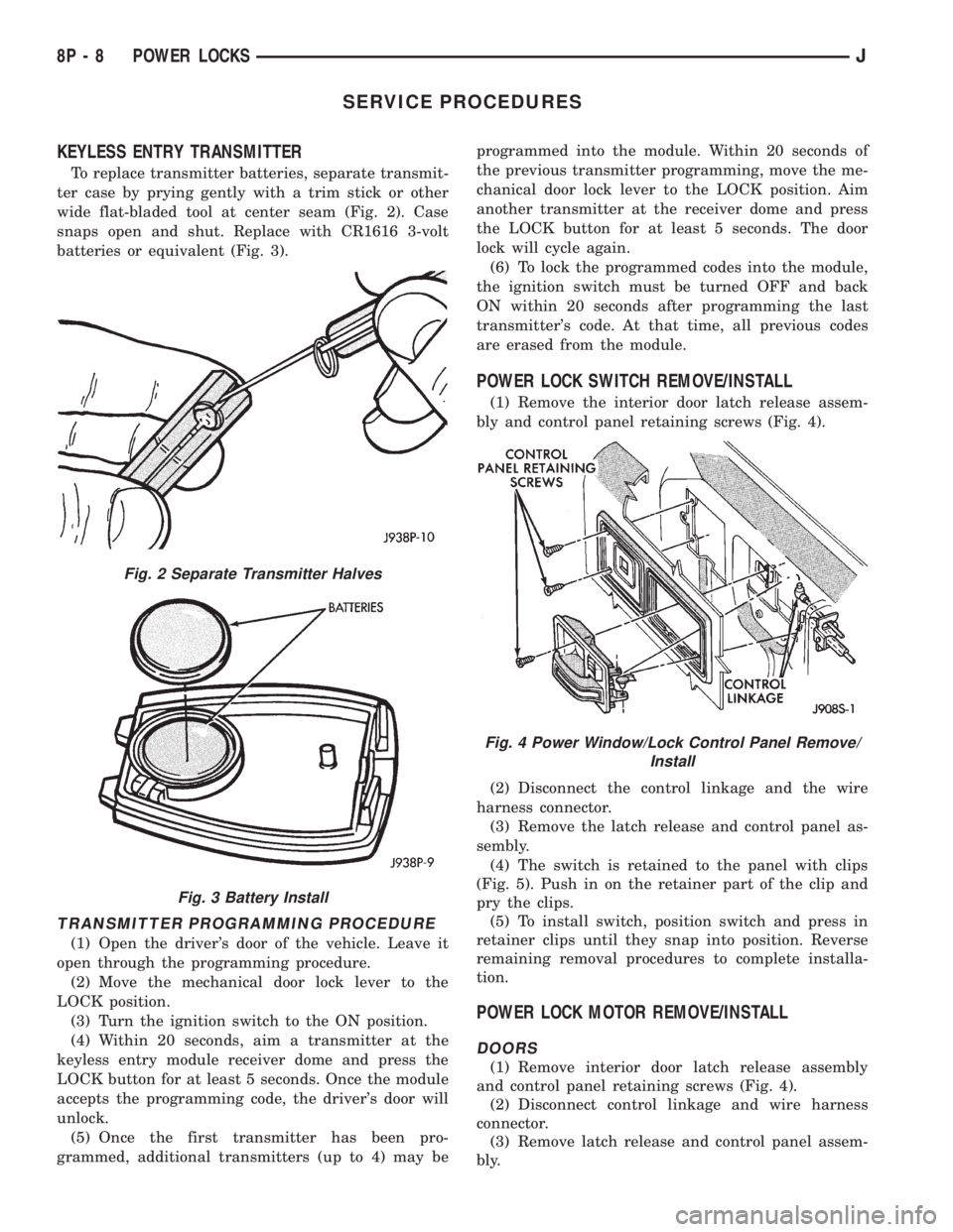
To replace transmitter batteries, separate transmit-
ter case by prying gently with a trim stick or other
wide flat-bladed tool at center seam (Fig. 2). Case
snaps open and shut. Replace with CR1616 3-volt
batteries or equivalent (Fig. 3).
TRANSMITTER PROGRAMMING PROCEDURE
(1) Open the driver's door of the vehicle. Leave it
open through the programming procedure.
(2) Move the mechanical door lock lever to the
LOCK position.
(3) Turn the ignition switch to the ON position.
(4) Within 20 seconds, aim a transmitter at the
keyless entry module receiver dome and press the
LOCK button for at least 5 seconds. Once the module
accepts the programming code, the driver's door will
unlock.
(5) Once the first transmitter has been pro-
grammed, additional transmitters (up to 4) may beprogrammed into the module. Within 20 seconds of
the previous transmitter programming, move the me-
chanical door lock lever to the LOCK position. Aim
another transmitter at the receiver dome and press
the LOCK button for at least 5 seconds. The door
lock will cycle again.
(6) To lock the programmed codes into the module,
the ignition switch must be turned OFF and back
ON within 20 seconds after programming the last
transmitter's code. At that time, all previous codes
are erased from the module.
POWER LOCK SWITCH REMOVE/INSTALL
(1) Remove the interior door latch release assem-
bly and control panel retaining screws (Fig. 4).
(2) Disconnect the control linkage and the wire
harness connector.
(3) Remove the latch release and control panel as-
sembly.
(4) The switch is retained to the panel with clips
(Fig. 5). Push in on the retainer part of the clip and
pry the clips.
(5) To install switch, position switch and press in
retainer clips until they snap into position. Reverse
remaining removal procedures to complete installa-
tion.
POWER LOCK MOTOR REMOVE/INSTALL
DOORS
(1) Remove interior door latch release assembly
and control panel retaining screws (Fig. 4).
(2) Disconnect control linkage and wire harness
connector.
(3) Remove latch release and control panel assem-
bly.
Fig. 2 Separate Transmitter Halves
Fig. 3 Battery Install
Fig. 4 Power Window/Lock Control Panel Remove/
Install
8P - 8 POWER LOCKSJ
Page 497 of 2198
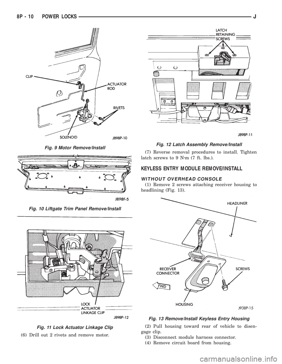
(6) Drill out 2 rivets and remove motor.(7) Reverse removal procedures to install. Tighten
latch screws to 9 Nzm (7 ft. lbs.).
KEYLESS ENTRY MODULE REMOVE/INSTALL
WITHOUT OVERHEAD CONSOLE
(1) Remove 2 screws attaching receiver housing to
headlining (Fig. 13).
(2) Pull housing toward rear of vehicle to disen-
gage clip.
(3) Disconnect module harness connector.
(4) Remove circuit board from housing.
Fig. 9 Motor Remove/Install
Fig. 10 Liftgate Trim Panel Remove/Install
Fig. 11 Lock Actuator Linkage Clip
Fig. 12 Latch Assembly Remove/Install
Fig. 13 Remove/Install Keyless Entry Housing
8P - 10 POWER LOCKSJ
Page 498 of 2198
(5) Reverse removal procedures to install.
WITH OVERHEAD CONSOLE
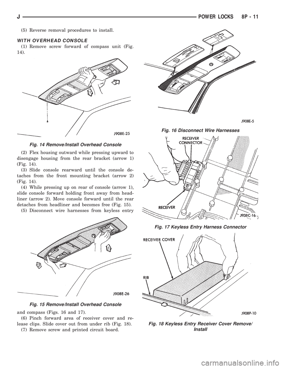
(1) Remove screw forward of compass unit (Fig.
14).
(2) Flex housing outward while pressing upward to
disengage housing from the rear bracket (arrow 1)
(Fig. 14).
(3) Slide console rearward until the console de-
taches from the front mounting bracket (arrow 2)
(Fig. 14).
(4) While pressing up on rear of console (arrow 1),
slide console forward holding front away from head-
liner (arrow 2). Move console forward until the rear
detaches from headliner and becomes free (Fig. 15).
(5) Disconnect wire harnesses from keyless entry
and compass (Figs. 16 and 17).
(6) Pinch forward area of receiver cover and re-
lease clips. Slide cover out from under rib (Fig. 18).
(7) Remove screw and printed circuit board.
Fig. 14 Remove/Install Overhead Console
Fig. 15 Remove/Install Overhead Console
Fig. 16 Disconnect Wire Harnesses
Fig. 17 Keyless Entry Harness Connector
Fig. 18 Keyless Entry Receiver Cover Remove/
Install
JPOWER LOCKS 8P - 11
Page 499 of 2198
(8) Reverse removal procedures to install. Be sure
to flex housing outward near the keyless entry mod-
ule until the console snaps onto the rear mounting
bracket.
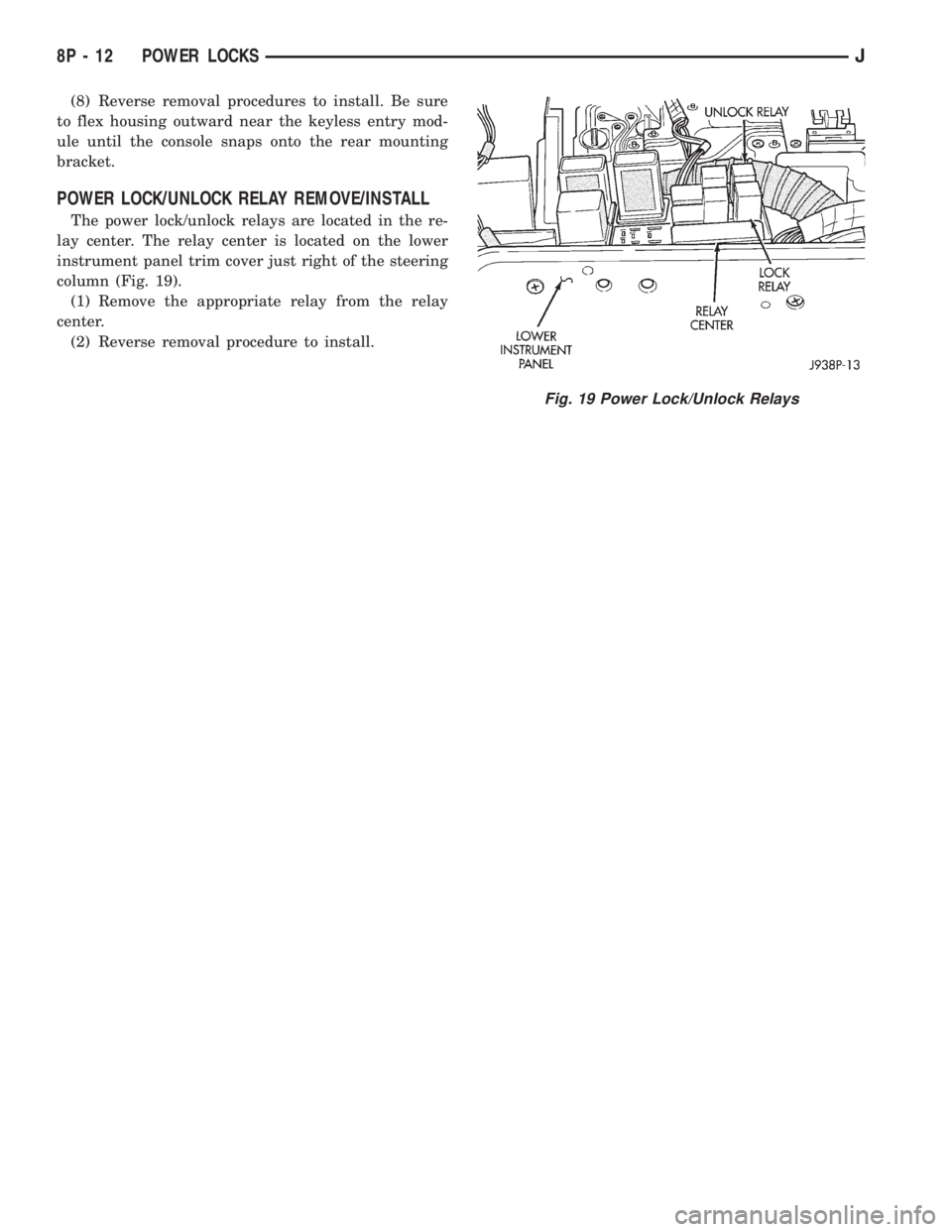
POWER LOCK/UNLOCK RELAY REMOVE/INSTALL
The power lock/unlock relays are located in the re-
lay center. The relay center is located on the lower
instrument panel trim cover just right of the steering
column (Fig. 19).
(1) Remove the appropriate relay from the relay
center.
(2) Reverse removal procedure to install.
Fig. 19 Power Lock/Unlock Relays
8P - 12 POWER LOCKSJ
Page 518 of 2198
CHIME/BUZZER WARNING SYSTEMS
CONTENTS
page page
DIAGNOSIS............................. 2
GENERAL INFORMATION.................. 1SERVICE PROCEDURES................... 4
GENERAL INFORMATION
This group covers the buzzer warning system,
which is standard equipment on XJ (Cherokee)/YJ
(Wrangler) models. The system provides an audible
warning to the driver when it monitors the following
conditions:
²key is in ignition switch with the driver's door
open
²head or park lamps are on with driver's door open
(XJ only)
²driver's seat belt is not buckled with ignition
switch in ON position.
Following are general descriptions of the major
components in the buzzer warning system. Refer to
Group 8W - Wiring Diagrams for complete circuit de-
scriptions and diagrams.
BUZZER MODULE
The buzzer module is located in the fuseblock mod-
ule under the left end of the instrument panel. It re-
ceives battery voltage at all times from (fuse 15 - XJ,
fuse 3 - YJ) the fuseblock module. It also receives a
second battery feed (fuse 17 - XJ, fuse 9 - YJ) when
the ignition switch is in the ON or START position.
Other inputs to the module include the driver's door
jamb switch, the driver's seat belt switch, the ignition
key-in switch, and the headlamp switch (XJ only). The
only output of the module is a timed 4 to 8 second feed
to the seat belt reminder lamp in the message center of
the instrument cluster. The timer function begins after
the ignition switch is turned to the ON position.
The buzzer module can not be repaired. If faulty, it
must be replaced.
DRIVER'S DOOR JAMB SWITCH
The driver's door jamb switch is mounted to the
driver's door hinge pillar. The switch closes a path to
ground for the buzzer module through the key-in
switch or headlamp switch (XJ only) when the driv-
er's door is opened, and opens when the driver's door
is closed. This switch can not be repaired. If faulty, it
must be replaced.
IGNITION KEY-IN SWITCH
XJ MODELS
The key-in switch is integral to the ignition switch,
which is mounted on the right side of the steering col-
umn. It closes a path to ground for the buzzer module
when the ignition key is inserted in the ignition lock cyl-
inder and the driver's door jamb switch is closed (door
open). The switch opens when the key is removed from
the ignition lock cylinder. This switch can not be re-
paired. If faulty, the entire ignition switch must be re-
placed. Refer to Group 8D - Ignition Systems for service
procedures.
YJ MODELS
The key-in switch is mounted within the steering col-
umn in the lock cylinder housing. It closes a path to
ground for the buzzer module when the ignition key is
inserted in the ignition lock cylinder and the driver's
door jamb switch is closed (door open). The switch opens
when the key is removed from the ignition lock cylinder.
This switch is available for service replacement. Refer
to Group 19 - Steering for service procedures.
HEADLAMP SWITCH (XJ ONLY)
The headlamp switch is located in the instrument
panel. It closes a path to ground for the buzzer module
when the park or headlamps are on and the driver's
door jamb switch is closed (door open). The switch opens
the ground path when the park and headlamps are
turned off. The headlamp switch can not be repaired. If
faulty, it must be replaced. Refer to Group 8E - Instru-
ment Panel and Gauges for service procedures.
DRIVER'S SEAT BELT SWITCH
The driver's seat belt switch is integral to the driv-
er's seat belt buckle-half assembly. The switch is nor-
mally closed, providing a ground path to the buzzer
module. When the tip-half of the seat belt is inserted
into the seat belt buckle, the switch opens the buzzer
module ground path. The seat belt switch can not be
repaired. If faulty, the entire driver's seat belt buck-
le-half must be replaced. Refer to Group 23 - Body
Components for service procedures.
JCHIME/BUZZER WARNING SYSTEMS 8U - 1
Page 519 of 2198
DIAGNOSIS
BUZZER MODULE
(1) Check fuses (15 and 17 - XJ, 3 and 9 - YJ) in
the fuseblock module. If fuses are OK, go to next
step. If not OK, replace fuses as required.
(2) Check for battery voltage at fuse (15 - XJ, 3 -
YJ) in fuseblock module. If OK, go to next step. If not
OK, repair feed circuit from power distribution center
as required.
(3) Turn ignition switch to ON position. Check for
battery voltage at fuse (17 - XJ, 9 - YJ) in the fuse-
block module. If OK, go to next step. If not OK, re-
pair feed from ignition switch as required.
(4) Turn ignition switch to OFF position. Replace
buzzer module with a known good unit and test op-
eration. If not OK, remove buzzer module and go to
next step.
(5) Check for battery voltage at cavity for buzzer
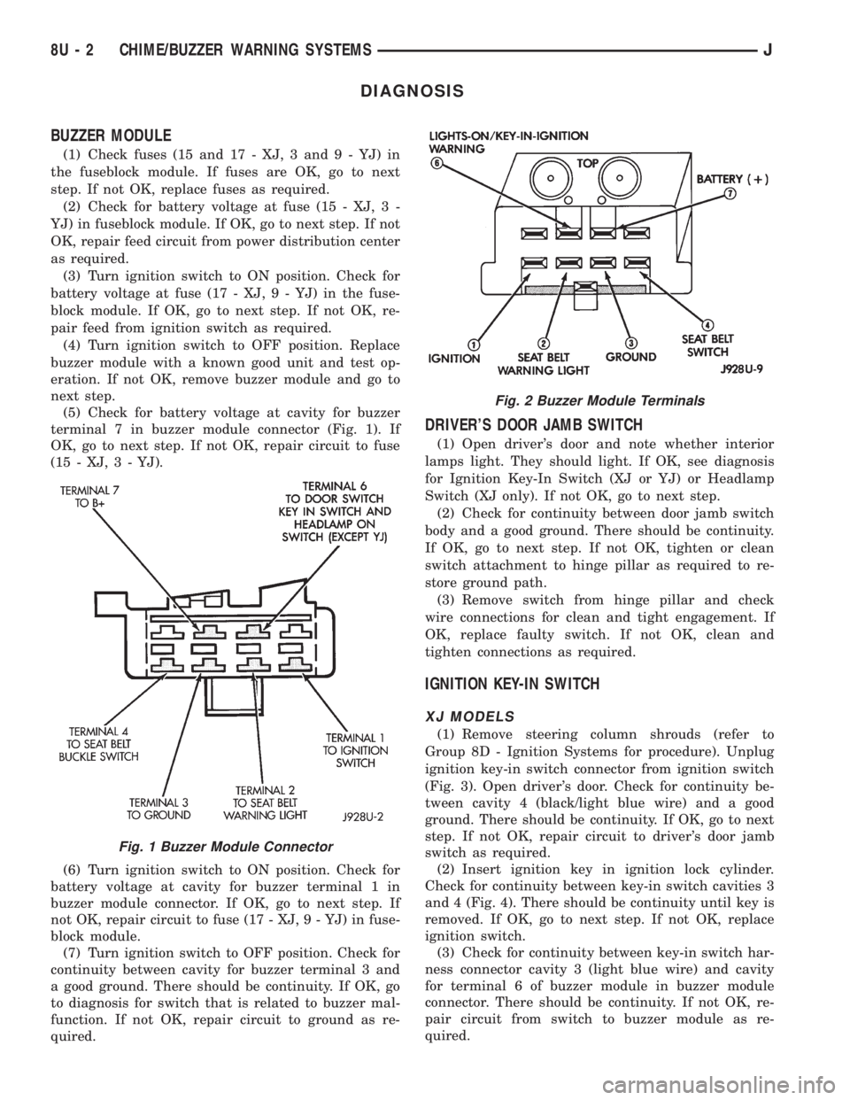
terminal 7 in buzzer module connector (Fig. 1). If
OK, go to next step. If not OK, repair circuit to fuse
(15 - XJ, 3 - YJ).
(6) Turn ignition switch to ON position. Check for
battery voltage at cavity for buzzer terminal 1 in
buzzer module connector. If OK, go to next step. If
not OK, repair circuit to fuse (17 - XJ, 9 - YJ) in fuse-
block module.
(7) Turn ignition switch to OFF position. Check for
continuity between cavity for buzzer terminal 3 and
a good ground. There should be continuity. If OK, go
to diagnosis for switch that is related to buzzer mal-
function. If not OK, repair circuit to ground as re-
quired.
DRIVER'S DOOR JAMB SWITCH
(1) Open driver's door and note whether interior
lamps light. They should light. If OK, see diagnosis
for Ignition Key-In Switch (XJ or YJ) or Headlamp
Switch (XJ only). If not OK, go to next step.
(2) Check for continuity between door jamb switch
body and a good ground. There should be continuity.
If OK, go to next step. If not OK, tighten or clean
switch attachment to hinge pillar as required to re-
store ground path.
(3) Remove switch from hinge pillar and check
wire connections for clean and tight engagement. If
OK, replace faulty switch. If not OK, clean and
tighten connections as required.
IGNITION KEY-IN SWITCH
XJ MODELS
(1) Remove steering column shrouds (refer to
Group 8D - Ignition Systems for procedure). Unplug
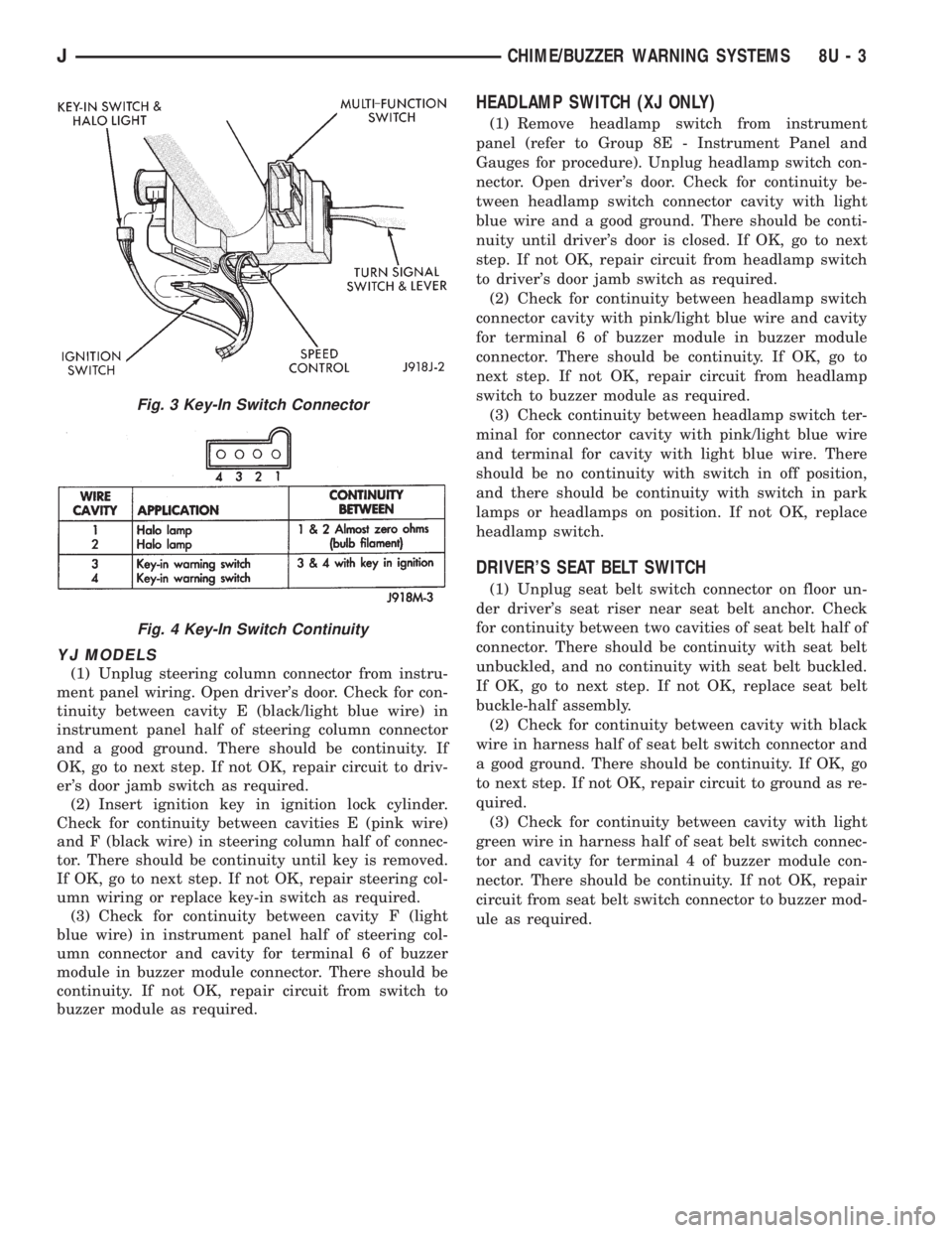
ignition key-in switch connector from ignition switch
(Fig. 3). Open driver's door. Check for continuity be-
tween cavity 4 (black/light blue wire) and a good
ground. There should be continuity. If OK, go to next
step. If not OK, repair circuit to driver's door jamb
switch as required.
(2) Insert ignition key in ignition lock cylinder.
Check for continuity between key-in switch cavities 3
and 4 (Fig. 4). There should be continuity until key is
removed. If OK, go to next step. If not OK, replace
ignition switch.
(3) Check for continuity between key-in switch har-
ness connector cavity 3 (light blue wire) and cavity
for terminal 6 of buzzer module in buzzer module
connector. There should be continuity. If not OK, re-
pair circuit from switch to buzzer module as re-
quired.
Fig. 1 Buzzer Module Connector
Fig. 2 Buzzer Module Terminals
8U - 2 CHIME/BUZZER WARNING SYSTEMSJ
Page 520 of 2198
YJ MODELS
(1) Unplug steering column connector from instru-
ment panel wiring. Open driver's door. Check for con-
tinuity between cavity E (black/light blue wire) in
instrument panel half of steering column connector
and a good ground. There should be continuity. If
OK, go to next step. If not OK, repair circuit to driv-
er's door jamb switch as required.
(2) Insert ignition key in ignition lock cylinder.
Check for continuity between cavities E (pink wire)
and F (black wire) in steering column half of connec-
tor. There should be continuity until key is removed.
If OK, go to next step. If not OK, repair steering col-
umn wiring or replace key-in switch as required.
(3) Check for continuity between cavity F (light
blue wire) in instrument panel half of steering col-
umn connector and cavity for terminal 6 of buzzer
module in buzzer module connector. There should be
continuity. If not OK, repair circuit from switch to
buzzer module as required.
HEADLAMP SWITCH (XJ ONLY)
(1) Remove headlamp switch from instrument
panel (refer to Group 8E - Instrument Panel and
Gauges for procedure). Unplug headlamp switch con-
nector. Open driver's door. Check for continuity be-
tween headlamp switch connector cavity with light
blue wire and a good ground. There should be conti-
nuity until driver's door is closed. If OK, go to next
step. If not OK, repair circuit from headlamp switch
to driver's door jamb switch as required.
(2) Check for continuity between headlamp switch
connector cavity with pink/light blue wire and cavity
for terminal 6 of buzzer module in buzzer module
connector. There should be continuity. If OK, go to
next step. If not OK, repair circuit from headlamp
switch to buzzer module as required.
(3) Check continuity between headlamp switch ter-
minal for connector cavity with pink/light blue wire
and terminal for cavity with light blue wire. There
should be no continuity with switch in off position,
and there should be continuity with switch in park
lamps or headlamps on position. If not OK, replace
headlamp switch.
DRIVER'S SEAT BELT SWITCH
(1) Unplug seat belt switch connector on floor un-
der driver's seat riser near seat belt anchor. Check
for continuity between two cavities of seat belt half of
connector. There should be continuity with seat belt
unbuckled, and no continuity with seat belt buckled.
If OK, go to next step. If not OK, replace seat belt
buckle-half assembly.
(2) Check for continuity between cavity with black
wire in harness half of seat belt switch connector and
a good ground. There should be continuity. If OK, go
to next step. If not OK, repair circuit to ground as re-
quired.
(3) Check for continuity between cavity with light
green wire in harness half of seat belt switch connec-
tor and cavity for terminal 4 of buzzer module con-
nector. There should be continuity. If not OK, repair
circuit from seat belt switch connector to buzzer mod-
ule as required.
Fig. 3 Key-In Switch Connector
Fig. 4 Key-In Switch Continuity
JCHIME/BUZZER WARNING SYSTEMS 8U - 3