1995 JEEP CHEROKEE battery location
[x] Cancel search: battery locationPage 1109 of 2198
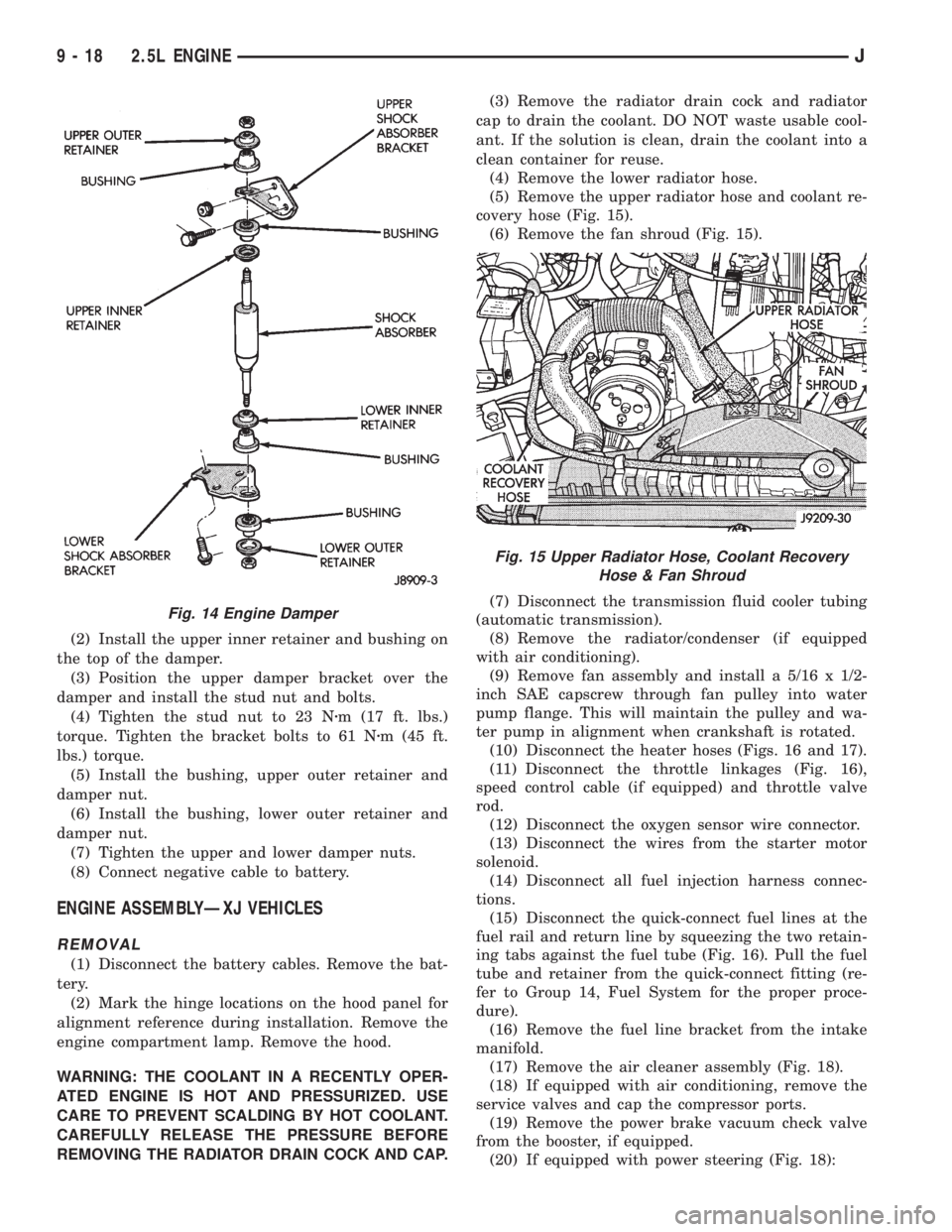
(2) Install the upper inner retainer and bushing on
the top of the damper.
(3) Position the upper damper bracket over the
damper and install the stud nut and bolts.
(4) Tighten the stud nut to 23 Nzm (17 ft. lbs.)
torque. Tighten the bracket bolts to 61 Nzm (45 ft.
lbs.) torque.
(5) Install the bushing, upper outer retainer and
damper nut.
(6) Install the bushing, lower outer retainer and
damper nut.
(7) Tighten the upper and lower damper nuts.
(8) Connect negative cable to battery.
ENGINE ASSEMBLYÐXJ VEHICLES
REMOVAL
(1) Disconnect the battery cables. Remove the bat-
tery.
(2) Mark the hinge locations on the hood panel for
alignment reference during installation. Remove the
engine compartment lamp. Remove the hood.
WARNING: THE COOLANT IN A RECENTLY OPER-
ATED ENGINE IS HOT AND PRESSURIZED. USE
CARE TO PREVENT SCALDING BY HOT COOLANT.
CAREFULLY RELEASE THE PRESSURE BEFORE
REMOVING THE RADIATOR DRAIN COCK AND CAP.(3) Remove the radiator drain cock and radiator
cap to drain the coolant. DO NOT waste usable cool-
ant. If the solution is clean, drain the coolant into a
clean container for reuse.
(4) Remove the lower radiator hose.
(5) Remove the upper radiator hose and coolant re-
covery hose (Fig. 15).
(6) Remove the fan shroud (Fig. 15).
(7) Disconnect the transmission fluid cooler tubing
(automatic transmission).
(8) Remove the radiator/condenser (if equipped
with air conditioning).
(9) Remove fan assembly and install a 5/16 x 1/2-
inch SAE capscrew through fan pulley into water
pump flange. This will maintain the pulley and wa-
ter pump in alignment when crankshaft is rotated.
(10) Disconnect the heater hoses (Figs. 16 and 17).
(11) Disconnect the throttle linkages (Fig. 16),
speed control cable (if equipped) and throttle valve
rod.
(12) Disconnect the oxygen sensor wire connector.
(13) Disconnect the wires from the starter motor
solenoid.
(14) Disconnect all fuel injection harness connec-
tions.
(15) Disconnect the quick-connect fuel lines at the
fuel rail and return line by squeezing the two retain-
ing tabs against the fuel tube (Fig. 16). Pull the fuel
tube and retainer from the quick-connect fitting (re-
fer to Group 14, Fuel System for the proper proce-
dure).
(16) Remove the fuel line bracket from the intake
manifold.
(17) Remove the air cleaner assembly (Fig. 18).
(18) If equipped with air conditioning, remove the
service valves and cap the compressor ports.
(19) Remove the power brake vacuum check valve
from the booster, if equipped.
(20) If equipped with power steering (Fig. 18):
Fig. 14 Engine Damper
Fig. 15 Upper Radiator Hose, Coolant Recovery
Hose & Fan Shroud
9 - 18 2.5L ENGINEJ
Page 1114 of 2198
(3) Connect the CCV hoses (Fig. 1).
(4) Connect negative cable to battery.
VALVE COMPONENT REPLACEÐCYLINDER HEAD
NOT REMOVED
ROCKER ARMS AND PUSH RODS
This procedure can be done with the engine in or
out of the vehicle.
REMOVAL
(1) Remove the engine cylinder head cover.
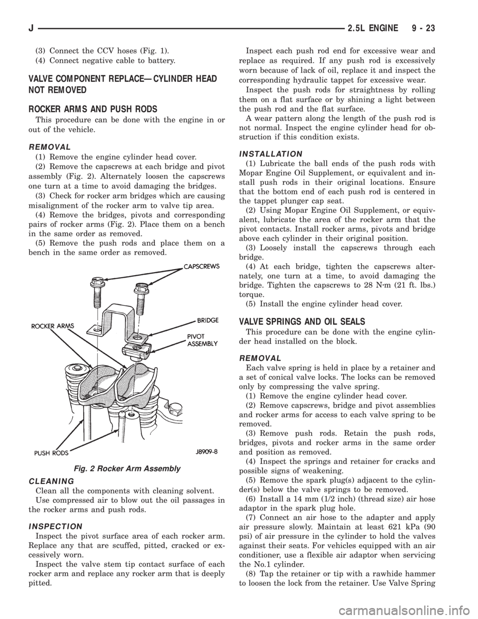
(2) Remove the capscrews at each bridge and pivot
assembly (Fig. 2). Alternately loosen the capscrews
one turn at a time to avoid damaging the bridges.
(3) Check for rocker arm bridges which are causing
misalignment of the rocker arm to valve tip area.
(4) Remove the bridges, pivots and corresponding
pairs of rocker arms (Fig. 2). Place them on a bench
in the same order as removed.
(5) Remove the push rods and place them on a
bench in the same order as removed.
CLEANING
Clean all the components with cleaning solvent.
Use compressed air to blow out the oil passages in
the rocker arms and push rods.
INSPECTION
Inspect the pivot surface area of each rocker arm.
Replace any that are scuffed, pitted, cracked or ex-
cessively worn.
Inspect the valve stem tip contact surface of each
rocker arm and replace any rocker arm that is deeply
pitted.Inspect each push rod end for excessive wear and
replace as required. If any push rod is excessively
worn because of lack of oil, replace it and inspect the
corresponding hydraulic tappet for excessive wear.
Inspect the push rods for straightness by rolling
them on a flat surface or by shining a light between
the push rod and the flat surface.
A wear pattern along the length of the push rod is
not normal. Inspect the engine cylinder head for ob-
struction if this condition exists.
INSTALLATION
(1) Lubricate the ball ends of the push rods with
Mopar Engine Oil Supplement, or equivalent and in-
stall push rods in their original locations. Ensure
that the bottom end of each push rod is centered in
the tappet plunger cap seat.
(2) Using Mopar Engine Oil Supplement, or equiv-
alent, lubricate the area of the rocker arm that the
pivot contacts. Install rocker arms, pivots and bridge
above each cylinder in their original position.
(3) Loosely install the capscrews through each
bridge.
(4) At each bridge, tighten the capscrews alter-
nately, one turn at a time, to avoid damaging the
bridge. Tighten the capscrews to 28 Nzm (21 ft. lbs.)
torque.
(5) Install the engine cylinder head cover.
VALVE SPRINGS AND OIL SEALS
This procedure can be done with the engine cylin-
der head installed on the block.
REMOVAL
Each valve spring is held in place by a retainer and
a set of conical valve locks. The locks can be removed
only by compressing the valve spring.
(1) Remove the engine cylinder head cover.
(2) Remove capscrews, bridge and pivot assemblies
and rocker arms for access to each valve spring to be
removed.
(3) Remove push rods. Retain the push rods,
bridges, pivots and rocker arms in the same order
and position as removed.
(4) Inspect the springs and retainer for cracks and
possible signs of weakening.
(5) Remove the spark plug(s) adjacent to the cylin-
der(s) below the valve springs to be removed.
(6) Install a 14 mm (1/2 inch) (thread size) air hose
adaptor in the spark plug hole.
(7) Connect an air hose to the adapter and apply
air pressure slowly. Maintain at least 621 kPa (90
psi) of air pressure in the cylinder to hold the valves
against their seats. For vehicles equipped with an air
conditioner, use a flexible air adaptor when servicing
the No.1 cylinder.
(8) Tap the retainer or tip with a rawhide hammer
to loosen the lock from the retainer. Use Valve Spring
Fig. 2 Rocker Arm Assembly
J2.5L ENGINE 9 - 23
Page 1116 of 2198
LEAK-DOWN TEST
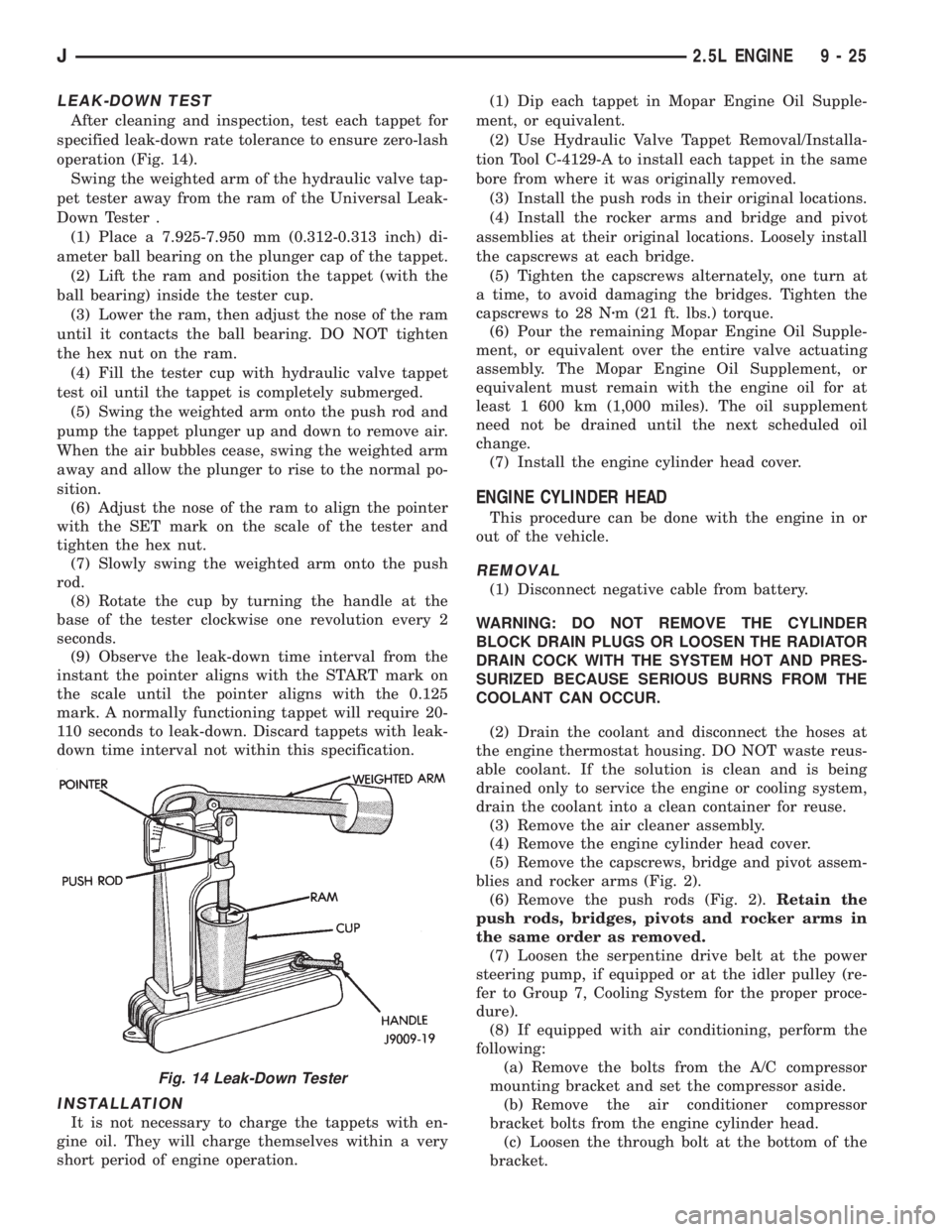
After cleaning and inspection, test each tappet for
specified leak-down rate tolerance to ensure zero-lash
operation (Fig. 14).
Swing the weighted arm of the hydraulic valve tap-
pet tester away from the ram of the Universal Leak-
Down Tester .
(1) Place a 7.925-7.950 mm (0.312-0.313 inch) di-
ameter ball bearing on the plunger cap of the tappet.
(2) Lift the ram and position the tappet (with the
ball bearing) inside the tester cup.
(3) Lower the ram, then adjust the nose of the ram
until it contacts the ball bearing. DO NOT tighten
the hex nut on the ram.
(4) Fill the tester cup with hydraulic valve tappet
test oil until the tappet is completely submerged.
(5) Swing the weighted arm onto the push rod and
pump the tappet plunger up and down to remove air.
When the air bubbles cease, swing the weighted arm
away and allow the plunger to rise to the normal po-
sition.
(6) Adjust the nose of the ram to align the pointer
with the SET mark on the scale of the tester and
tighten the hex nut.
(7) Slowly swing the weighted arm onto the push
rod.
(8) Rotate the cup by turning the handle at the
base of the tester clockwise one revolution every 2
seconds.
(9) Observe the leak-down time interval from the
instant the pointer aligns with the START mark on
the scale until the pointer aligns with the 0.125
mark. A normally functioning tappet will require 20-
110 seconds to leak-down. Discard tappets with leak-
down time interval not within this specification.
INSTALLATION
It is not necessary to charge the tappets with en-
gine oil. They will charge themselves within a very
short period of engine operation.(1) Dip each tappet in Mopar Engine Oil Supple-
ment, or equivalent.
(2) Use Hydraulic Valve Tappet Removal/Installa-
tion Tool C-4129-A to install each tappet in the same
bore from where it was originally removed.
(3) Install the push rods in their original locations.
(4) Install the rocker arms and bridge and pivot
assemblies at their original locations. Loosely install
the capscrews at each bridge.
(5) Tighten the capscrews alternately, one turn at
a time, to avoid damaging the bridges. Tighten the
capscrews to 28 Nzm (21 ft. lbs.) torque.
(6) Pour the remaining Mopar Engine Oil Supple-
ment, or equivalent over the entire valve actuating
assembly. The Mopar Engine Oil Supplement, or
equivalent must remain with the engine oil for at
least 1 600 km (1,000 miles). The oil supplement
need not be drained until the next scheduled oil
change.
(7) Install the engine cylinder head cover.
ENGINE CYLINDER HEAD
This procedure can be done with the engine in or
out of the vehicle.
REMOVAL
(1) Disconnect negative cable from battery.
WARNING: DO NOT REMOVE THE CYLINDER
BLOCK DRAIN PLUGS OR LOOSEN THE RADIATOR
DRAIN COCK WITH THE SYSTEM HOT AND PRES-
SURIZED BECAUSE SERIOUS BURNS FROM THE
COOLANT CAN OCCUR.
(2) Drain the coolant and disconnect the hoses at
the engine thermostat housing. DO NOT waste reus-
able coolant. If the solution is clean and is being
drained only to service the engine or cooling system,
drain the coolant into a clean container for reuse.
(3) Remove the air cleaner assembly.
(4) Remove the engine cylinder head cover.
(5) Remove the capscrews, bridge and pivot assem-
blies and rocker arms (Fig. 2).
(6) Remove the push rods (Fig. 2).Retain the
push rods, bridges, pivots and rocker arms in
the same order as removed.
(7) Loosen the serpentine drive belt at the power
steering pump, if equipped or at the idler pulley (re-
fer to Group 7, Cooling System for the proper proce-
dure).
(8) If equipped with air conditioning, perform the
following:
(a) Remove the bolts from the A/C compressor
mounting bracket and set the compressor aside.
(b) Remove the air conditioner compressor
bracket bolts from the engine cylinder head.
(c) Loosen the through bolt at the bottom of the
bracket.
Fig. 14 Leak-Down Tester
J2.5L ENGINE 9 - 25
Page 1147 of 2198
The digits of the code identify:
(1) 1st DigitÐThe year (4 = 1994).
(2) 2nd & 3rd DigitsÐThe month (01 - 12).
(3) 4th & 5th DigitsÐThe engine type/fuel system/
compression ratio (MX = A 4.0 Liter (242 CID) 8.7:1
compression ratio engine with a multi-point fuel in-
jection system).
(4) 6th & 7th DigitsÐThe day of engine build (01 -
31).
FOR EXAMPLE:Code * 401MX12 * identifies a
4.0 Liter (242 CID) engine with a multi-point fuel in-
jection system, 8.7:1 compression ratio and built on
January 12, 1994.
OVERSIZE AND UNDERSIZE COMPONENT
CODES
Some engines may be built with oversize or under-
size components such as:
²Oversize cylinder bores.
²Oversize camshaft bearing bores.
²Undersize crankshaft main bearing journals.
²Undersize connecting rod journals.
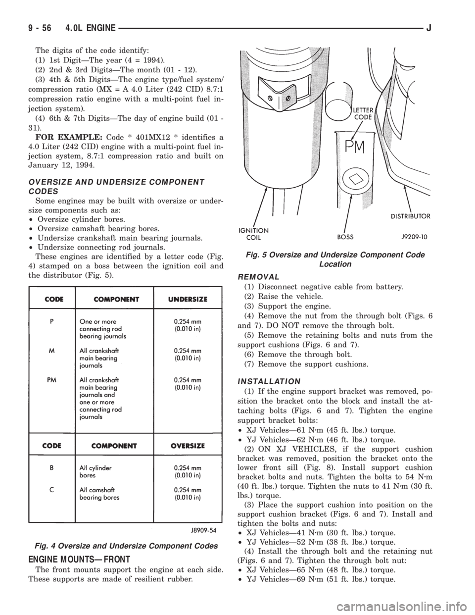
These engines are identified by a letter code (Fig.
4) stamped on a boss between the ignition coil and
the distributor (Fig. 5).
ENGINE MOUNTSÐFRONT
The front mounts support the engine at each side.
These supports are made of resilient rubber.
REMOVAL
(1) Disconnect negative cable from battery.
(2) Raise the vehicle.
(3) Support the engine.
(4) Remove the nut from the through bolt (Figs. 6
and 7). DO NOT remove the through bolt.
(5) Remove the retaining bolts and nuts from the
support cushions (Figs. 6 and 7).
(6) Remove the through bolt.
(7) Remove the support cushions.
INSTALLATION
(1) If the engine support bracket was removed, po-
sition the bracket onto the block and install the at-
taching bolts (Figs. 6 and 7). Tighten the engine
support bracket bolts:
²XJ VehiclesÐ61 Nzm (45 ft. lbs.) torque.
²YJ VehiclesÐ62 Nzm (46 ft. lbs.) torque.
(2) ON XJ VEHICLES, if the support cushion
bracket was removed, position the bracket onto the
lower front sill (Fig. 8). Install support cushion
bracket bolts and nuts. Tighten the bolts to 54 Nzm
(40 ft. lbs.) torque. Tighten the nuts to 41 Nzm (30 ft.
lbs.) torque.
(3) Place the support cushion into position on the
support cushion bracket (Figs. 6 and 7). Install and
tighten the bolts and nuts:
²XJ VehiclesÐ41 Nzm (30 ft. lbs.) torque.
²YJ VehiclesÐ52 Nzm (38 ft. lbs.) torque.
(4) Install the through bolt and the retaining nut
(Figs. 6 and 7). Tighten the through bolt nut:
²XJ VehiclesÐ65 Nzm (48 ft. lbs.) torque.
²YJ VehiclesÐ69 Nzm (51 ft. lbs.) torque.
Fig. 4 Oversize and Undersize Component Codes
Fig. 5 Oversize and Undersize Component Code
Location
9 - 56 4.0L ENGINEJ
Page 1150 of 2198
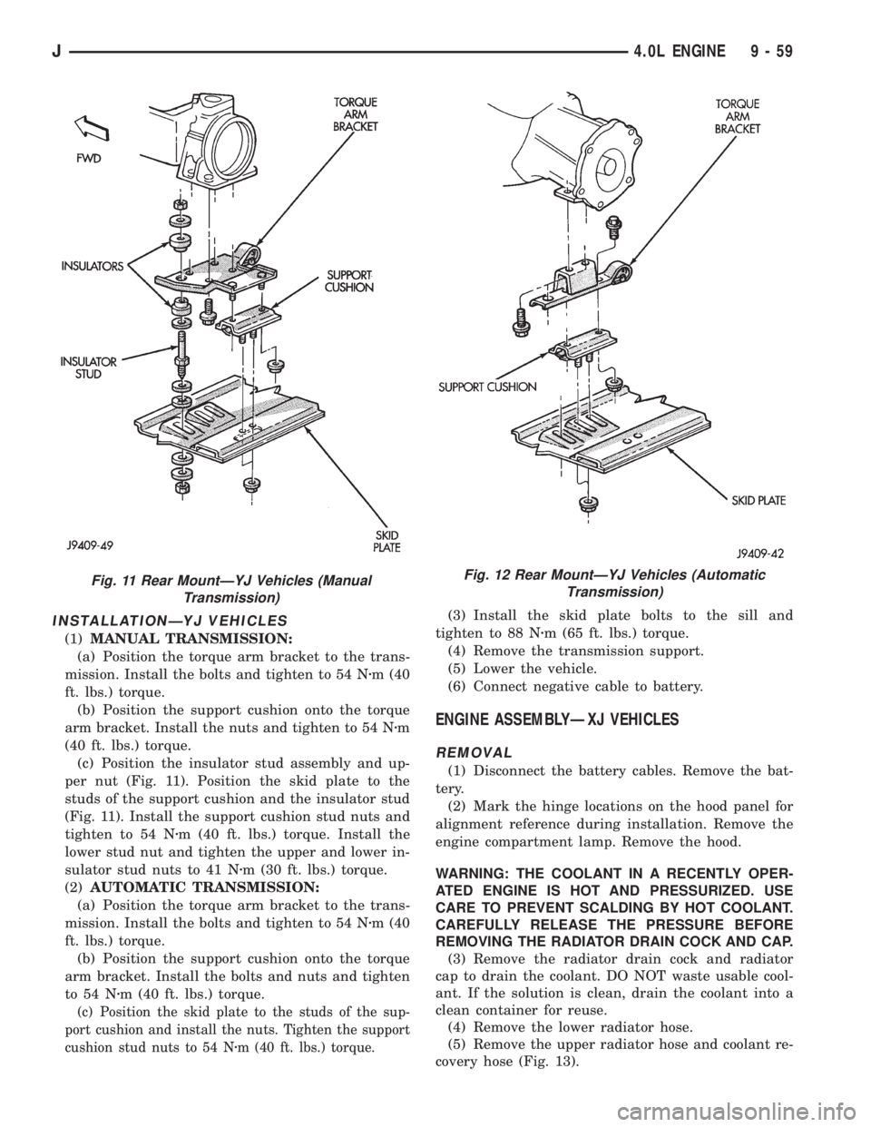
INSTALLATIONÐYJ VEHICLES
(1)MANUAL TRANSMISSION:
(a) Position the torque arm bracket to the trans-
mission. Install the bolts and tighten to 54 Nzm (40
ft. lbs.) torque.
(b) Position the support cushion onto the torque
arm bracket. Install the nuts and tighten to 54 Nzm
(40 ft. lbs.) torque.
(c) Position the insulator stud assembly and up-
per nut (Fig. 11). Position the skid plate to the
studs of the support cushion and the insulator stud
(Fig. 11). Install the support cushion stud nuts and
tighten to 54 Nzm (40 ft. lbs.) torque. Install the
lower stud nut and tighten the upper and lower in-
sulator stud nuts to 41 Nzm (30 ft. lbs.) torque.
(2)AUTOMATIC TRANSMISSION:
(a) Position the torque arm bracket to the trans-
mission. Install the bolts and tighten to 54 Nzm (40
ft. lbs.) torque.
(b) Position the support cushion onto the torque
arm bracket. Install the bolts and nuts and tighten
to 54 Nzm (40 ft. lbs.) torque.
(c) Position the skid plate to the studs of the sup-
port cushion and install the nuts. Tighten the support
cushion stud nuts to 54 Nzm (40 ft. lbs.) torque.
(3) Install the skid plate bolts to the sill and
tighten to 88 Nzm (65 ft. lbs.) torque.
(4) Remove the transmission support.
(5) Lower the vehicle.
(6) Connect negative cable to battery.
ENGINE ASSEMBLYÐXJ VEHICLES
REMOVAL
(1) Disconnect the battery cables. Remove the bat-
tery.
(2) Mark the hinge locations on the hood panel for
alignment reference during installation. Remove the
engine compartment lamp. Remove the hood.
WARNING: THE COOLANT IN A RECENTLY OPER-
ATED ENGINE IS HOT AND PRESSURIZED. USE
CARE TO PREVENT SCALDING BY HOT COOLANT.
CAREFULLY RELEASE THE PRESSURE BEFORE
REMOVING THE RADIATOR DRAIN COCK AND CAP.
(3) Remove the radiator drain cock and radiator
cap to drain the coolant. DO NOT waste usable cool-
ant. If the solution is clean, drain the coolant into a
clean container for reuse.
(4) Remove the lower radiator hose.
(5) Remove the upper radiator hose and coolant re-
covery hose (Fig. 13).
Fig. 11 Rear MountÐYJ Vehicles (Manual
Transmission)Fig. 12 Rear MountÐYJ Vehicles (Automatic
Transmission)
J4.0L ENGINE 9 - 59
Page 1158 of 2198
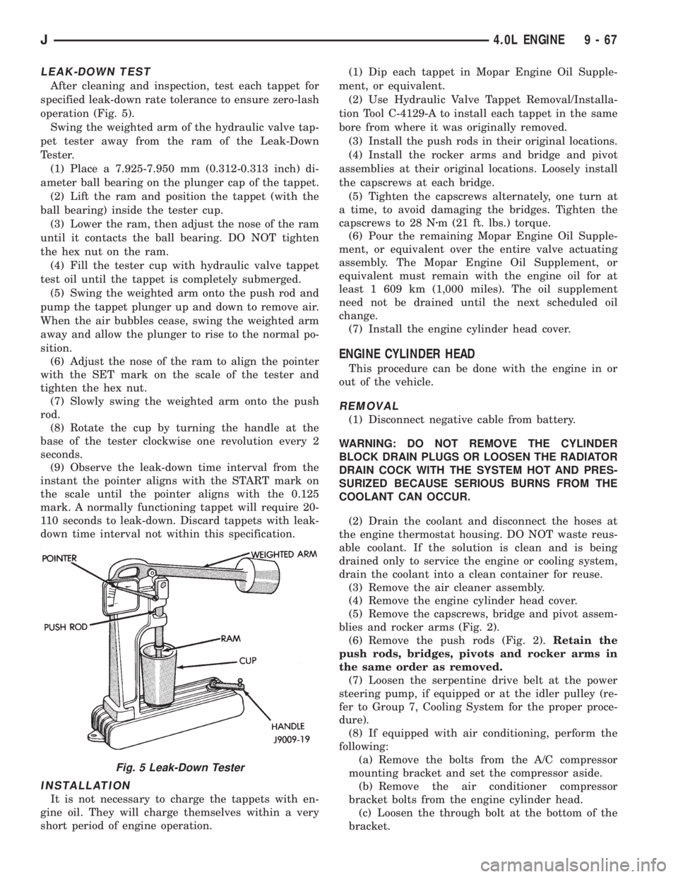
LEAK-DOWN TEST
After cleaning and inspection, test each tappet for
specified leak-down rate tolerance to ensure zero-lash
operation (Fig. 5).
Swing the weighted arm of the hydraulic valve tap-
pet tester away from the ram of the Leak-Down
Tester.
(1) Place a 7.925-7.950 mm (0.312-0.313 inch) di-
ameter ball bearing on the plunger cap of the tappet.
(2) Lift the ram and position the tappet (with the
ball bearing) inside the tester cup.
(3) Lower the ram, then adjust the nose of the ram
until it contacts the ball bearing. DO NOT tighten
the hex nut on the ram.
(4) Fill the tester cup with hydraulic valve tappet
test oil until the tappet is completely submerged.
(5) Swing the weighted arm onto the push rod and
pump the tappet plunger up and down to remove air.
When the air bubbles cease, swing the weighted arm
away and allow the plunger to rise to the normal po-
sition.
(6) Adjust the nose of the ram to align the pointer
with the SET mark on the scale of the tester and
tighten the hex nut.
(7) Slowly swing the weighted arm onto the push
rod.
(8) Rotate the cup by turning the handle at the
base of the tester clockwise one revolution every 2
seconds.
(9) Observe the leak-down time interval from the
instant the pointer aligns with the START mark on
the scale until the pointer aligns with the 0.125
mark. A normally functioning tappet will require 20-
110 seconds to leak-down. Discard tappets with leak-
down time interval not within this specification.
INSTALLATION
It is not necessary to charge the tappets with en-
gine oil. They will charge themselves within a very
short period of engine operation.(1) Dip each tappet in Mopar Engine Oil Supple-
ment, or equivalent.
(2) Use Hydraulic Valve Tappet Removal/Installa-
tion Tool C-4129-A to install each tappet in the same
bore from where it was originally removed.
(3) Install the push rods in their original locations.
(4) Install the rocker arms and bridge and pivot
assemblies at their original locations. Loosely install
the capscrews at each bridge.
(5) Tighten the capscrews alternately, one turn at
a time, to avoid damaging the bridges. Tighten the
capscrews to 28 Nzm (21 ft. lbs.) torque.
(6) Pour the remaining Mopar Engine Oil Supple-
ment, or equivalent over the entire valve actuating
assembly. The Mopar Engine Oil Supplement, or
equivalent must remain with the engine oil for at
least 1 609 km (1,000 miles). The oil supplement
need not be drained until the next scheduled oil
change.
(7) Install the engine cylinder head cover.
ENGINE CYLINDER HEAD
This procedure can be done with the engine in or
out of the vehicle.
REMOVAL
(1) Disconnect negative cable from battery.
WARNING: DO NOT REMOVE THE CYLINDER
BLOCK DRAIN PLUGS OR LOOSEN THE RADIATOR
DRAIN COCK WITH THE SYSTEM HOT AND PRES-
SURIZED BECAUSE SERIOUS BURNS FROM THE
COOLANT CAN OCCUR.
(2) Drain the coolant and disconnect the hoses at
the engine thermostat housing. DO NOT waste reus-
able coolant. If the solution is clean and is being
drained only to service the engine or cooling system,
drain the coolant into a clean container for reuse.
(3) Remove the air cleaner assembly.
(4) Remove the engine cylinder head cover.
(5) Remove the capscrews, bridge and pivot assem-
blies and rocker arms (Fig. 2).
(6) Remove the push rods (Fig. 2).Retain the
push rods, bridges, pivots and rocker arms in
the same order as removed.
(7) Loosen the serpentine drive belt at the power
steering pump, if equipped or at the idler pulley (re-
fer to Group 7, Cooling System for the proper proce-
dure).
(8) If equipped with air conditioning, perform the
following:
(a) Remove the bolts from the A/C compressor
mounting bracket and set the compressor aside.
(b) Remove the air conditioner compressor
bracket bolts from the engine cylinder head.
(c) Loosen the through bolt at the bottom of the
bracket.
Fig. 5 Leak-Down Tester
J4.0L ENGINE 9 - 67
Page 1180 of 2198
If the clearance exceeds specification using a pair
of 0.051 mm (0.002 inch) undersize bearing inserts,
measure crankshaft journal diameter with a mi-
crometer. If the journal diameter is correct, the
crankshaft bore in the cylinder block may be mis-
aligned, which requires cylinder block replacement or
machining to true bore.
Replace the crankshaft or grind to accept the ap-
propriate undersize bearing inserts if:
²Journal diameters 1 through 6 are less than
63.4517 mm (2.4981 inches)
²Journal 7 diameter is less than 63.4365 mm
(2.4975 inches).
Once the proper clearances have been obtained,
proceed to Crankshaft Main BearingÐInstallation.
MAIN BEARING JOURNAL DIAMETER (CRANKSHAFT
REMOVED)
Remove the crankshaft from the cylinder block (re-
fer to Cylinder Block - Disassemble).
Clean the oil off the main bearing journal.
Determine the maximum diameter of the journal
with a micrometer. Measure at two locations 90É
apart at each end of the journal.
The maximum allowable taper and out of round is
0.013 mm (0.0005 inch). Compare the measured di-
ameter with the journal diameter specification (Main
Bearing Fitting Chart). Select inserts required to ob-
tain the specified bearing-to-journal clearance.
Install the crankshaft into the cylinder block (refer
to Cylinder Block - Assemble and Crankshaft Main
Bearings - Installation).
INSTALLATION
(1) Lubricate the bearing surface of each insert
with engine oil.
(2) Loosen all the main bearing caps. Install the
main bearing upper inserts.
(3) Install the lower bearing inserts into the main
bearing caps.
(4) Install the main bearing cap(s) and lower in-
sert(s).
(5) Tighten the bolts of caps 1, 2, 4, 5, 6, and 7 to
54 Nzm (40 ft. lbs.) torque. Now tighten these bolts to
95 Nzm (70 ft. lbs.) torque. Finally, tighten these
bolts to 108 Nzm (80 ft. lbs.) torque.
(6) Push the crankshaft forward and backward.
Load the crankshaft front or rear and tighten cap
bolt No.3 to 54 Nzm (40 ft. lbs.) torque. Then tighten
to 95 Nzm (70 ft. lbs.) torque and finally tighten to
108 Nzm (80 ft. lbs.) torque.
(7) Rotate the crankshaft after tightening each
main bearing cap to ensure the crankshaft rotates
freely.
(8) Check crankshaft end play. Crankshaft end
play is controlled by the thrust bearing which is
flange and installed at the No.2 main bearing posi-
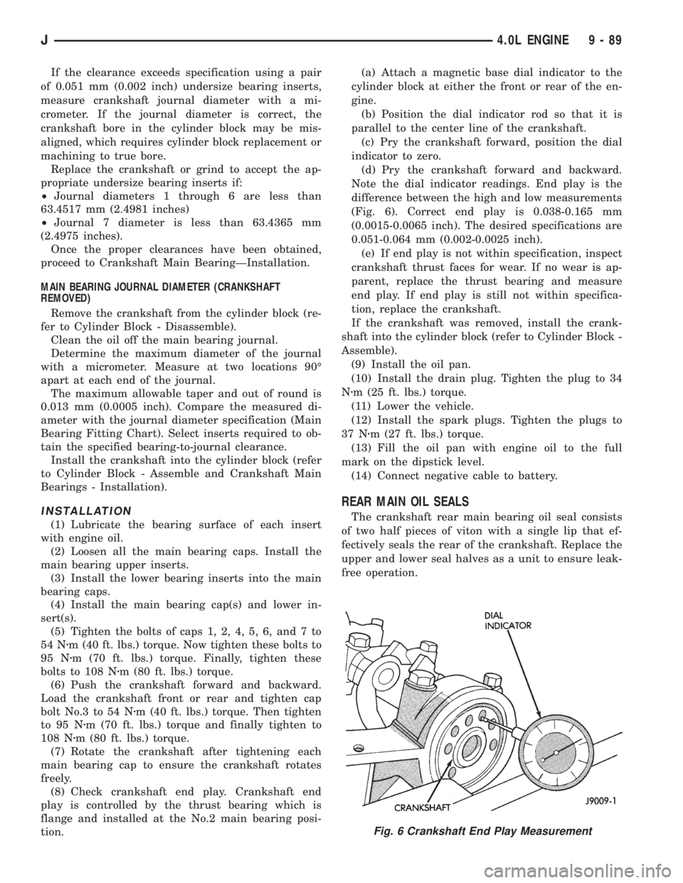
tion.(a) Attach a magnetic base dial indicator to the
cylinder block at either the front or rear of the en-
gine.
(b) Position the dial indicator rod so that it is
parallel to the center line of the crankshaft.
(c) Pry the crankshaft forward, position the dial
indicator to zero.
(d) Pry the crankshaft forward and backward.
Note the dial indicator readings. End play is the
difference between the high and low measurements
(Fig. 6). Correct end play is 0.038-0.165 mm
(0.0015-0.0065 inch). The desired specifications are
0.051-0.064 mm (0.002-0.0025 inch).
(e) If end play is not within specification, inspect
crankshaft thrust faces for wear. If no wear is ap-
parent, replace the thrust bearing and measure
end play. If end play is still not within specifica-
tion, replace the crankshaft.
If the crankshaft was removed, install the crank-
shaft into the cylinder block (refer to Cylinder Block -
Assemble).
(9) Install the oil pan.
(10) Install the drain plug. Tighten the plug to 34
Nzm (25 ft. lbs.) torque.
(11) Lower the vehicle.
(12) Install the spark plugs. Tighten the plugs to
37 Nzm (27 ft. lbs.) torque.
(13) Fill the oil pan with engine oil to the full
mark on the dipstick level.
(14) Connect negative cable to battery.
REAR MAIN OIL SEALS
The crankshaft rear main bearing oil seal consists
of two half pieces of viton with a single lip that ef-
fectively seals the rear of the crankshaft. Replace the
upper and lower seal halves as a unit to ensure leak-
free operation.
Fig. 6 Crankshaft End Play Measurement
J4.0L ENGINE 9 - 89
Page 1231 of 2198
(2) Raise skid plate/fuel tank until gauge sender
wire connector can be connected to harness connec-
tor.
(3) Finish raising skid plate/fuel tank assembly
into position. Tighten mounting nuts to 16 Nzm (12
ft. lbs.) torque. Remove transmission jack.
(4) Connect fuel fill hose and fill vent hose to filler
neck. Tighten hose clamps.
(5) Connect vent hose to vent tube.
(6) Connect fuel supply hose to the supply tube
and fuel return hose to return tube. Tighten hose
clamps.
(7) Install fuel filler neck shroud with push clips.
(8) Lower vehicle.
(9) Fill fuel tank. Install filler cap.
(10) Connect negative battery cable to battery.
(11) Start vehicle and inspect for leaks.
FUEL GAUGE SENDING UNIT
The fuel gauge sending unit is attached to the fuel
pump module. Refer to Fuel Pump Module in the
Fuel Delivery System section of this group.
FUEL TANK PRESSURE RELIEF/ROLLOVER VALVE
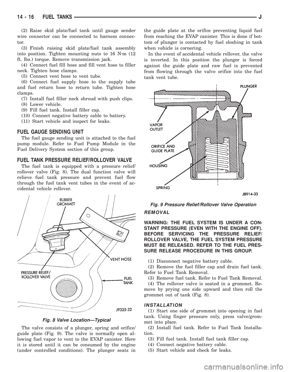
The fuel tank is equipped with a pressure relief/
rollover valve (Fig. 8). The dual function valve will
relieve fuel tank pressure and prevent fuel flow
through the fuel tank vent tubes in the event of ac-
cidental vehicle rollover.
The valve consists of a plunger, spring and orifice/
guide plate (Fig. 9). The valve is normally open al-
lowing fuel vapor to vent to the EVAP canister. Here
it is stored until it can be consumed by the engine
(under controlled conditions). The plunger seats inthe guide plate at the orifice preventing liquid fuel
from reaching the EVAP canister. This is done if bot-
tom of plunger is contacted by fuel sloshing in tank
when vehicle is cornering.
In the event of accidental vehicle rollover, the valve
is inverted. In this position the plunger is forced
against the guide plate and raw fuel is prevented
from flowing through the valve orifice into the fuel
tank vent tube.
REMOVAL
WARNING: THE FUEL SYSTEM IS UNDER A CON-
STANT PRESSURE (EVEN WITH THE ENGINE OFF).
BEFORE SERVICING THE PRESSURE RELIEF/
ROLLOVER VALVE, THE FUEL SYSTEM PRESSURE
MUST BE RELEASED. REFER TO THE FUEL PRES-
SURE RELEASE PROCEDURE IN THIS GROUP.
(1) Disconnect negative battery cable.
(2) Remove the fuel filler cap and drain fuel tank.
Refer to Fuel Tank Removal.
(3) Remove fuel tank. Refer to Fuel Tank Removal.
(4) The rollover valve is seated in a grommet. Re-
move by prying one side upward and then roll the
grommet out of tank (Fig. 8).
INSTALLATION
(1) Start one side of grommet into opening in fuel
tank. Using finger pressure only, press valve/grom-
met into place.
(2) Install fuel tank. Refer to Fuel Tank Installa-
tion.
(3) Fill fuel tank. Install fuel tank filler cap.
(4) Connect negative battery cable.
(5) Start vehicle and check for leaks.
Fig. 8 Valve LocationÐTypical
Fig. 9 Pressure Relief/Rollover Valve Operation
14 - 16 FUEL TANKSJ