1995 JEEP CHEROKEE Fuse block
[x] Cancel search: Fuse blockPage 494 of 2198
POWER LOCK MOTOR
(1) Once it is determined which lock motor is inop-
erative, that motor can be tested. Disconnect the wire
connector at the motor. Apply 12 volts to the motor
terminals to check its operation in one direction. Re-
verse the polarity to check the operation in the other
direction. If OK, repair circuits to power lock/unlock
relays as required. If not OK, replace the motor.
(2) If all lock motors are inoperative, the problem
may be caused by one shorted motor. Disconnecting a
shorted motor will allow the good motors to operate.
Disconnect each motor connector, one at a time, and
re-check both lock and unlock functions while operat-
ing the door lock switch. If disconnecting one motor
causes the other motors to become functional, go
back to step 1 to test the disconnected motor.
KEYLESS ENTRY TRANSMITTER
(1) Depress either transmitter button and note
whether red Light-Emitting Diode (LED) on trans-
mitter case lights. If OK, go to next step. If not OK,
replace batteries as described under Keyless Entry
Transmitter in Service Procedures. Test transmitter
operation. If OK, discard faulty batteries. If not OK,
go to next step.
(2) Perform transmitter program procedure with
suspect transmitter and another known good trans-
mitter, as described in Service Procedures. Test oper-
ation with both transmitters. If both transmitters fail
to operate power locks, see Keyless Entry Module di-
agnosis. If known good transmitter operates power
locks and suspect transmitter does not, replace faulty
transmitter. Be certain to perform transmitter pro-
gram procedure again when replacing faulty trans-
mitter and to erase test transmitter access code from
keyless entry module.
KEYLESS ENTRY MODULE
(1) Check fuse 9 in fuseblock module. If OK, go to
next step. If not OK, replace fuse.
(2) Check for battery voltage at fuse 9. If OK, go to
next step. If not OK, repair circuit from power distri-
bution center.
(3) Access keyless entry module connectors as de-
scribed in Keyless Entry Module Remove/Install.
(4) Unplug module connector from module. Check
connector and receptacle in module for loose, cor-
roded, or damaged terminals and pins. If OK, go to
next step. If not OK, repair as required.
(5) Probe connector cavity for module terminal 1
and check for battery voltage. If OK, go to next step.
If not OK, repair circuit to fuse 9 as required.
(6) Install a jumper wire from connector cavity for
module terminal 1 to connector cavity for module ter-
minal 3. Doors should lock. If OK, go to step 8. If not
OK, go to next step.
(7) Check for continuity between connector cavity
for module terminal 3 and lock relay terminal 3 (86).
There should be continuity. If OK, replace lock relay.
If not OK, repair circuit as required.
(8) Install a jumper wire from connector cavity for
module terminal 1 to connector cavity for module ter-
minal 4. Doors should unlock. If OK, replace module.
If not OK, go to next step.
(9) Check for continuity between connector cavity
for module terminal 4 and unlock relay terminal 3
(86). There should be continuity. If OK, replace un-
lock relay. If not OK, repair circuit as required.
JPOWER LOCKS 8P - 7
Page 500 of 2198
POWER SEATS
CONTENTS
page page
DIAGNOSIS............................. 2
GENERAL INFORMATION.................. 1SERVICE PROCEDURES................... 3
GENERAL INFORMATION
A six-way driver's side power seat is an available
option on XJ (Cherokee) models. The power seat sys-
tem receives battery feed through fuse 6 in the power
distribution center and circuit breaker 16 in the fuse-
block module at all times.
Following are general descriptions of the major
components in the power seat system. Refer to Group
8W - Wiring Diagrams for complete circuit descrip-
tions and diagrams.
POWER SEAT SWITCH
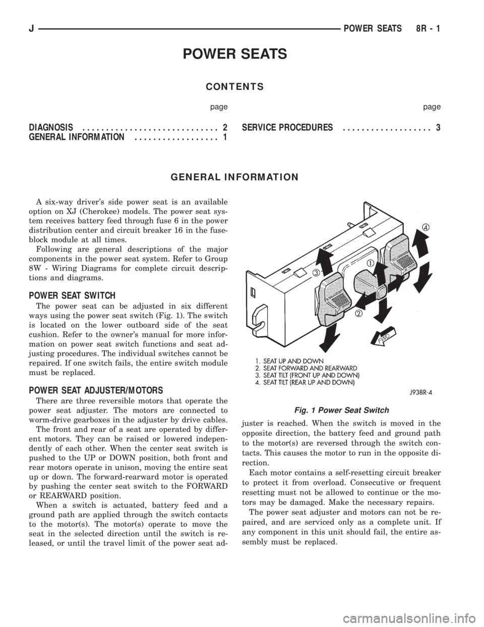
The power seat can be adjusted in six different
ways using the power seat switch (Fig. 1). The switch
is located on the lower outboard side of the seat
cushion. Refer to the owner's manual for more infor-
mation on power seat switch functions and seat ad-
justing procedures. The individual switches cannot be
repaired. If one switch fails, the entire switch module
must be replaced.
POWER SEAT ADJUSTER/MOTORS
There are three reversible motors that operate the
power seat adjuster. The motors are connected to
worm-drive gearboxes in the adjuster by drive cables.
The front and rear of a seat are operated by differ-
ent motors. They can be raised or lowered indepen-
dently of each other. When the center seat switch is
pushed to the UP or DOWN position, both front and
rear motors operate in unison, moving the entire seat
up or down. The forward-rearward motor is operated
by pushing the center seat switch to the FORWARD
or REARWARD position.
When a switch is actuated, battery feed and a
ground path are applied through the switch contacts
to the motor(s). The motor(s) operate to move the
seat in the selected direction until the switch is re-
leased, or until the travel limit of the power seat ad-juster is reached. When the switch is moved in the
opposite direction, the battery feed and ground path
to the motor(s) are reversed through the switch con-
tacts. This causes the motor to run in the opposite di-
rection.
Each motor contains a self-resetting circuit breaker
to protect it from overload. Consecutive or frequent
resetting must not be allowed to continue or the mo-
tors may be damaged. Make the necessary repairs.
The power seat adjuster and motors can not be re-
paired, and are serviced only as a complete unit. If
any component in this unit should fail, the entire as-
sembly must be replaced.
Fig. 1 Power Seat Switch
JPOWER SEATS 8R - 1
Page 501 of 2198
DIAGNOSIS
Before any testing is attempted the battery should
be fully charged and all connections and pins cleaned
and tightened to ensure proper continuity and
grounds.
With the dome lamp on, apply switch in direction
of the failure. If the dome lamp dims, the seat may
be jamming. Check for binding or obstructions. If the
dome lamp does not dim, then proceed with the fol-
lowing electrical tests.
POWER SEAT ADJUSTER/MOTORS
Operate the power seat switch to move all three
seat motors. The seat should move in all directions.
If not OK, proceed as follows. If one or more motors
operate, see diagnosis for Power Seat Switch.
(1) Check circuit breaker 16 in the fuseblock mod-
ule. If OK, go to next step. If not OK, replace circuit
breaker.
(2) Remove switch mounting screws and check for
battery voltage at red wire at switch connector. If
OK, go to next step. If not OK, repair wiring to cir-
cuit breaker.(3) Check for continuity between black wire at
switch connector and a good ground. There should be
continuity. If OK, go to next step. If not OK, repair
wiring to ground.
(4) See diagnosis for Power Seat Switch. If switch
continuity checks OK, replace faulty motor/adjuster
assembly. If switch continuity is not OK, replace
faulty switch.
POWER SEAT SWITCH
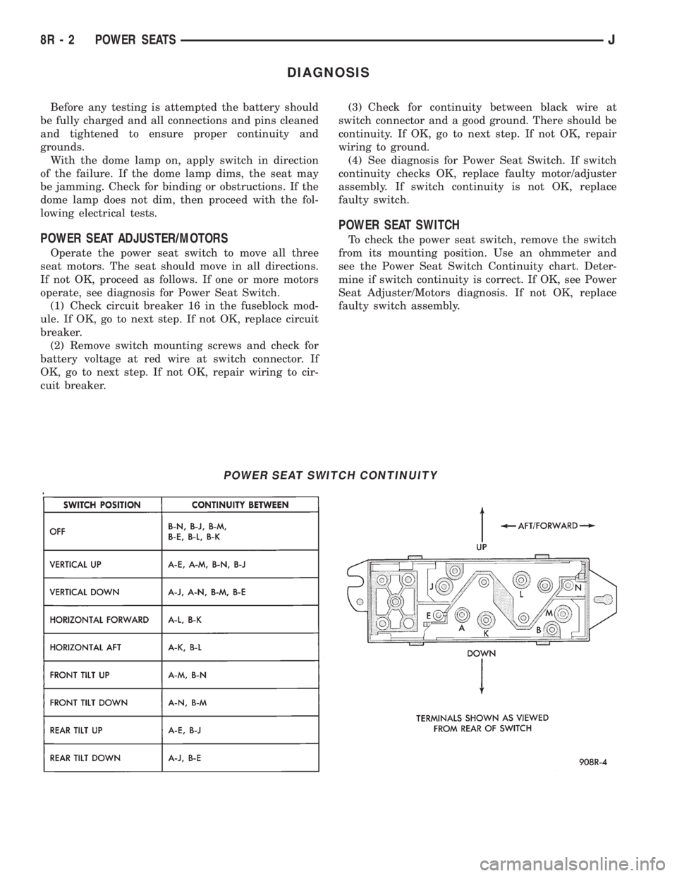
To check the power seat switch, remove the switch
from its mounting position. Use an ohmmeter and
see the Power Seat Switch Continuity chart. Deter-
mine if switch continuity is correct. If OK, see Power
Seat Adjuster/Motors diagnosis. If not OK, replace
faulty switch assembly.
POWER SEAT SWITCH CONTINUITY
8R - 2 POWER SEATSJ
Page 504 of 2198
POWER WINDOWS
CONTENTS
page page
DIAGNOSIS............................. 1
GENERAL INFORMATION.................. 1SERVICE PROCEDURES................... 7
GENERAL INFORMATION
Power door windows are optional equipment on XJ
(Cherokee) models. The power windows operate only
with the ignition switch in the ON position. This
group covers diagnosis and service of the electrical
components peculiar to the power window system.
For service of mechanical components such as the
regulator, lift plate or window tracks refer to Group
23 - Body Components.
Following are general descriptions of the major
components in the power window system. Refer to
Group 8W - Wiring Diagrams for complete circuit de-
scriptions and diagrams.
POWER WINDOW SWITCH
Both front and rear door windows can be raised or
lowered electrically by operating the four two-way
switches on the driver's door panel. A single two-way
switch on each passenger's door panel operates only
the window on that passenger's door. The switches
cannot be repaired. If faulty, they must be replaced.
POWER WINDOW MOTOR
A permanent magnet reversible motor moves the
window regulator through a cable and drum operat-ing mechanism. A positive and negative battery con-
nection to the two motor terminals will cause the
motor to rotate in one direction. Reversing current
through these same two connections will cause the
motor to rotate in the opposite direction. In addition,
each power window motor is equipped with an inte-
gral automatic re-setting circuit breaker to protect
the motor from overloads. The power window motor
and regulator assembly cannot be repaired. If faulty,
the entire assembly must be replaced.
CIRCUIT BREAKER
An automatic re-setting circuit breaker in the fuse-
block module is used to protect the power window
system circuit. The circuit breaker can protect the
system from a short circuit, and can also protect the
system from an overload condition caused by an ob-
structed or stuck window glass or regulator. The cir-
cuit breaker can not be repaired. If faulty, it must be
replaced.
DIAGNOSIS
It is necessary that the window be free to slide up
and down for the power window system to function
properly. If the window is not free to move up and
down, the motor will overload and trip the circuit
breaker. To determine if the glass is free, disconnect
regulator plate from the glass and slide window up
and down by hand.
An alternate method is to shake the glass in the
door, with the glass positioned between the up and
down stop positions. Check that the glass can be
moved slightly from side to side, front to rear, and up
and down. Then check that window is not boundtight in the tracks. If window is free, proceed with di-
agnosis that follows. If window is not free, refer to
Group 23 - Body Components for service procedures.
CIRCUIT BREAKER
Locate correct circuit breaker in fuseblock module.
Pull out slightly, but be sure that circuit breaker ter-
minals still contact terminals in fuseblock module.
Turn ignition switch to ON position. Connect ground
wire of voltmeter to a good ground. With probe of
voltmeter positive lead, check both terminals of cir-
cuit breaker for battery voltage. If only one terminal
JPOWER WINDOWS 8S - 1
Page 512 of 2198
POWER MIRRORS
CONTENTS
page page
DIAGNOSIS............................. 1
GENERAL INFORMATION.................. 1SERVICE PROCEDURES................... 4
GENERAL INFORMATION
Power outside rear view mirrors are an available
option on XJ (Cherokee) models. Following are gen-
eral descriptions of the major components in the
power mirror system. Refer to Group 8W - Wiring Di-
agrams for complete circuit descriptions and dia-
grams.
POWER MIRROR
The power mirrors are connected to battery feed at
all times. Each mirror head contains two electric mo-
tors, two drive mechanisms and the mirror glass.
One motor and drive controls mirror up-and-down
movement, and the other controls right-and-left
movement.
The mirror glass is the only serviced replacement
part for the power mirror assembly. If any other com-ponent of the mirror unit is faulty or damaged, the
entire assembly must be replaced.
POWER MIRROR SWITCH
Both the right and left mirror are controlled by a
multi-function switch located on the front of the cen-
ter console storage compartment, directly below the
armrest. The selector switch is moved right (right
mirror control), left (left mirror control), or center to
turn power mirrors off. Then one of four directional
control buttons is depressed to control movement of
the selected mirror up, down, right, or left. The
power mirror switch is serviced only as a complete
unit.
DIAGNOSIS
POWER MIRROR SYSTEM
(1) Check fuse 16 in Power Distribution Center
(PDC) and fuse 9 in fuseblock module. If OK, go to
next step. If not OK, replace fuse.
(2) Check for battery voltage at fuse 9 in fuseblock
module. If OK, go to next step. If not OK, repair cir-
cuit to fuse 16 in PDC.
(3) Remove power mirror switch from the center
console. See Power Mirror Switch Remove/Install.
(4) Disconnect wiring harness connector from
switch. Check for battery voltage at pink wire. If OK,
go to next step. If not OK, repair circuit to fuse 9 in
fuseblock module.
(5) Check for continuity between black wire in
switch harness connector and a good ground. There
should be continuity. If OK, go to next step. If not
OK, repair circuit to ground.
(6) Check switch continuity as shown in the Mirror
Switch Continuity charts. If OK, go to next step. If
not OK, replace switch.(7) See Power Mirror Switch illustration. Connect
a jumper wire from mirror switch connector cavity
for pin E to cavity for pin F. Now connect a second
jumper from connector cavity for pin G to each of the
following pin cavities: A, B, C, then D. In each case,
the selected mirror head should move. If OK, replace
switch. If not OK, go to next step.
(8) Remove door trim panel and unplug power mir-
ror connector inside door. Connect one jumper wire to
a good ground and a second jumper wire to a battery
feed. Connect other ends of jumpers to the mirror
side of connector in door (refer to Group 8W - Wiring
Diagrams for connector cavity identification). Mirror
head should move in each of the four directions. If
OK, repair wiring between mirror switch and door
connectors. If not OK, replace mirror.
JPOWER MIRRORS 8T - 1
Page 518 of 2198
CHIME/BUZZER WARNING SYSTEMS
CONTENTS
page page
DIAGNOSIS............................. 2
GENERAL INFORMATION.................. 1SERVICE PROCEDURES................... 4
GENERAL INFORMATION
This group covers the buzzer warning system,
which is standard equipment on XJ (Cherokee)/YJ
(Wrangler) models. The system provides an audible
warning to the driver when it monitors the following
conditions:
²key is in ignition switch with the driver's door
open
²head or park lamps are on with driver's door open
(XJ only)
²driver's seat belt is not buckled with ignition
switch in ON position.
Following are general descriptions of the major
components in the buzzer warning system. Refer to
Group 8W - Wiring Diagrams for complete circuit de-
scriptions and diagrams.
BUZZER MODULE
The buzzer module is located in the fuseblock mod-
ule under the left end of the instrument panel. It re-
ceives battery voltage at all times from (fuse 15 - XJ,
fuse 3 - YJ) the fuseblock module. It also receives a
second battery feed (fuse 17 - XJ, fuse 9 - YJ) when
the ignition switch is in the ON or START position.
Other inputs to the module include the driver's door
jamb switch, the driver's seat belt switch, the ignition
key-in switch, and the headlamp switch (XJ only). The
only output of the module is a timed 4 to 8 second feed
to the seat belt reminder lamp in the message center of
the instrument cluster. The timer function begins after
the ignition switch is turned to the ON position.
The buzzer module can not be repaired. If faulty, it
must be replaced.
DRIVER'S DOOR JAMB SWITCH
The driver's door jamb switch is mounted to the
driver's door hinge pillar. The switch closes a path to
ground for the buzzer module through the key-in
switch or headlamp switch (XJ only) when the driv-
er's door is opened, and opens when the driver's door
is closed. This switch can not be repaired. If faulty, it
must be replaced.
IGNITION KEY-IN SWITCH
XJ MODELS
The key-in switch is integral to the ignition switch,
which is mounted on the right side of the steering col-
umn. It closes a path to ground for the buzzer module
when the ignition key is inserted in the ignition lock cyl-
inder and the driver's door jamb switch is closed (door
open). The switch opens when the key is removed from
the ignition lock cylinder. This switch can not be re-
paired. If faulty, the entire ignition switch must be re-
placed. Refer to Group 8D - Ignition Systems for service
procedures.
YJ MODELS
The key-in switch is mounted within the steering col-
umn in the lock cylinder housing. It closes a path to
ground for the buzzer module when the ignition key is
inserted in the ignition lock cylinder and the driver's
door jamb switch is closed (door open). The switch opens
when the key is removed from the ignition lock cylinder.
This switch is available for service replacement. Refer
to Group 19 - Steering for service procedures.
HEADLAMP SWITCH (XJ ONLY)
The headlamp switch is located in the instrument
panel. It closes a path to ground for the buzzer module
when the park or headlamps are on and the driver's
door jamb switch is closed (door open). The switch opens
the ground path when the park and headlamps are
turned off. The headlamp switch can not be repaired. If
faulty, it must be replaced. Refer to Group 8E - Instru-
ment Panel and Gauges for service procedures.
DRIVER'S SEAT BELT SWITCH
The driver's seat belt switch is integral to the driv-
er's seat belt buckle-half assembly. The switch is nor-
mally closed, providing a ground path to the buzzer
module. When the tip-half of the seat belt is inserted
into the seat belt buckle, the switch opens the buzzer
module ground path. The seat belt switch can not be
repaired. If faulty, the entire driver's seat belt buck-
le-half must be replaced. Refer to Group 23 - Body
Components for service procedures.
JCHIME/BUZZER WARNING SYSTEMS 8U - 1
Page 519 of 2198
DIAGNOSIS
BUZZER MODULE
(1) Check fuses (15 and 17 - XJ, 3 and 9 - YJ) in
the fuseblock module. If fuses are OK, go to next
step. If not OK, replace fuses as required.
(2) Check for battery voltage at fuse (15 - XJ, 3 -
YJ) in fuseblock module. If OK, go to next step. If not
OK, repair feed circuit from power distribution center
as required.
(3) Turn ignition switch to ON position. Check for
battery voltage at fuse (17 - XJ, 9 - YJ) in the fuse-
block module. If OK, go to next step. If not OK, re-
pair feed from ignition switch as required.
(4) Turn ignition switch to OFF position. Replace
buzzer module with a known good unit and test op-
eration. If not OK, remove buzzer module and go to
next step.
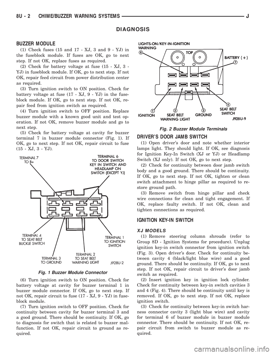
(5) Check for battery voltage at cavity for buzzer
terminal 7 in buzzer module connector (Fig. 1). If
OK, go to next step. If not OK, repair circuit to fuse
(15 - XJ, 3 - YJ).
(6) Turn ignition switch to ON position. Check for
battery voltage at cavity for buzzer terminal 1 in
buzzer module connector. If OK, go to next step. If
not OK, repair circuit to fuse (17 - XJ, 9 - YJ) in fuse-
block module.
(7) Turn ignition switch to OFF position. Check for
continuity between cavity for buzzer terminal 3 and
a good ground. There should be continuity. If OK, go
to diagnosis for switch that is related to buzzer mal-
function. If not OK, repair circuit to ground as re-
quired.
DRIVER'S DOOR JAMB SWITCH
(1) Open driver's door and note whether interior
lamps light. They should light. If OK, see diagnosis
for Ignition Key-In Switch (XJ or YJ) or Headlamp
Switch (XJ only). If not OK, go to next step.
(2) Check for continuity between door jamb switch
body and a good ground. There should be continuity.
If OK, go to next step. If not OK, tighten or clean
switch attachment to hinge pillar as required to re-
store ground path.
(3) Remove switch from hinge pillar and check
wire connections for clean and tight engagement. If
OK, replace faulty switch. If not OK, clean and
tighten connections as required.
IGNITION KEY-IN SWITCH
XJ MODELS
(1) Remove steering column shrouds (refer to
Group 8D - Ignition Systems for procedure). Unplug
ignition key-in switch connector from ignition switch
(Fig. 3). Open driver's door. Check for continuity be-
tween cavity 4 (black/light blue wire) and a good
ground. There should be continuity. If OK, go to next
step. If not OK, repair circuit to driver's door jamb
switch as required.
(2) Insert ignition key in ignition lock cylinder.
Check for continuity between key-in switch cavities 3
and 4 (Fig. 4). There should be continuity until key is
removed. If OK, go to next step. If not OK, replace
ignition switch.
(3) Check for continuity between key-in switch har-
ness connector cavity 3 (light blue wire) and cavity
for terminal 6 of buzzer module in buzzer module
connector. There should be continuity. If not OK, re-
pair circuit from switch to buzzer module as re-
quired.
Fig. 1 Buzzer Module Connector
Fig. 2 Buzzer Module Terminals
8U - 2 CHIME/BUZZER WARNING SYSTEMSJ
Page 526 of 2198
(2) Connect the other lead of the voltmeter to the
selected test point. The vehicle ignition may need to
be turned ON to check voltage. Refer to the appropri-
ate test procedure.
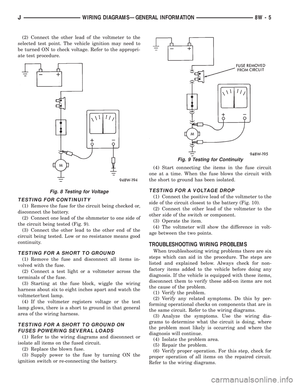
TESTING FOR CONTINUITY
(1) Remove the fuse for the circuit being checked or,
disconnect the battery.
(2) Connect one lead of the ohmmeter to one side of
the circuit being tested (Fig. 9).
(3) Connect the other lead to the other end of the
circuit being tested. Low or no resistance means good
continuity.
TESTING FOR A SHORT TO GROUND
(1) Remove the fuse and disconnect all items in-
volved with the fuse.
(2) Connect a test light or a voltmeter across the
terminals of the fuse.
(3) Starting at the fuse block, wiggle the wiring
harness about six to eight inches apart and watch the
voltmeter/test lamp.
(4) If the voltmeter registers voltage or the test
lamp glows, there is a short to ground in that general
area of the wiring harness.
TESTING FOR A SHORT TO GROUND ON
FUSES POWERING SEVERAL LOADS
(1) Refer to the wiring diagrams and disconnect or
isolate all items on the fused circuit.
(2) Replace the blown fuse.
(3) Supply power to the fuse by turning ON the
ignition switch or re-connecting the battery.(4) Start connecting the items in the fuse circuit
one at a time. When the fuse blows the circuit with
the short to ground has been isolated.
TESTING FOR A VOLTAGE DROP
(1) Connect the positive lead of the voltmeter to the
side of the circuit closest to the battery (Fig. 10).
(2) Connect the other lead of the voltmeter to the
other side of the switch or component.
(3) Operate the item.
(4) The voltmeter will show the difference in volt-
age between the two points.
TROUBLESHOOTING WIRING PROBLEMS
When troubleshooting wiring problems there are six
steps which can aid in the procedure. The steps are
listed and explained below. Always check for non-
factory items added to the vehicle before doing any
diagnosis. If the vehicle is equipped with these items,
disconnect them to verify these add-on items are not
the cause of the problem.
(1) Verify the problem.
(2) Verify any related symptoms. Do this by per-
forming operational checks on components that are in
the same circuit. Refer to the wiring diagrams.
(3) Analyze the symptoms. Use the wiring dia-
grams to determine what the circuit is doing, where
the problem most likely is occurring and where the
diagnosis will continue.
(4) Isolate the problem area.
(5) Repair the problem.
(6) Verify proper operation. For this step, check for
proper operation of all items on the repaired circuit.
Refer to the wiring diagrams.
Fig. 8 Testing for Voltage
Fig. 9 Testing for Continuity
JWIRING DIAGRAMSÐGENERAL INFORMATION 8W - 5