1995 JEEP CHEROKEE Fuse block
[x] Cancel search: Fuse blockPage 369 of 2198
voltage is supplied to one side of the indicator bulb. A
ground path for the bulb is provided by 3 switches.
The bulb will light when:
²the brake warning switch is closed (indicating un-
equal brake system hydraulic pressures possibly due
to brake fluid leakage)
²the ignition switch is in the START position (bulb
test)
²the parking brake switch is closed (parking brake
is applied).
Refer to Group 5 - Brakes for more information.
FOUR-WHEEL DRIVE INDICATOR LAMP
This lamp lights when the transfer case is engaged
in the 4H or 4L position. Voltage is supplied to one
side of the indicator bulb. A switch on the front axle
disconnect housing is connected to the other side of
the indicator bulb. When the switch is closed, a path
to ground is provided and the indicator bulb lights.
HEADLAMP HIGH BEAM INDICATOR LAMP
The high beam indicator lamp is controlled by the
headlamp dimmer switch. One side of the indicator
bulb is grounded at all times. The other side of the
bulb receives battery feed through the contacts of the
dimmer switch when the turn signal switch lever is
actuated to turn the headlamp high beams on. Refer
to Group 8L - Lamps for more information.
MALFUNCTION INDICATOR LAMP
The CHECK ENGINE or Malfunction Indicator
Lamp (MIL) lights each time the ignition switch is
turned ON, and stays on for 3 seconds as a bulb test.
If the Powertrain Control Module (PCM) receives an
incorrect signal or no signal from certain fuel or
emission system related circuits or components, the
lamp is turned on. This will indicate that the PCM
has recorded a Diagnostic Trouble Code (DTC) in
electronic memory for a circuit or component mal-
function. Refer to Group 14 - Fuel System for more
information.
SEAT BELT REMINDER LAMP
The seat belt reminder lamp lights for 4 to 8 sec-
onds after the ignition switch is turned to the ON po-sition. A timer in the chime/buzzer module controls
ignition-switched battery feed to the lamp. Refer to
Group 8U - Chime/Buzzer Warning Systems for more
information.
TURN SIGNAL INDICATOR LAMPS
The left and right turn signal indicator lamps are
controlled by the turn signal and hazard warning
switches. One side of the bulb for each lamp is
grounded at all times. The other side of the bulb re-
ceives battery feed through the contacts of the turn
signal switch, when the turn signal lever or hazard
warning button are actuated. Refer to Group 8J -
Turn Signal and Hazard Warning Systems for more
information.
UPSHIFT INDICATOR LAMP
Vehicles equipped with manual transmissions have
an optional upshift indicator lamp. Ground feed for
the lamp is switched by the Powertrain Control Mod-
ule (PCM). The lamp lights to indicate when the
driver should shift to the next highest gear for best
fuel economy. The PCM will turn the lamp off after 3
to 5 seconds if the upshift is not performed. The lamp
will remain off until the vehicle stops accelerating
and is brought back to the range of lamp operation,
or until the transmission is shifted into another gear.
The indicator lamp is normally on when the igni-
tion switch is turned ON and is turned off when the
engine is started. The lamp will be turned on during
vehicle operation according to engine speed and load.
CLUSTER ILLUMINATION LAMPS
All cluster illumination lamps receive battery feed
from the instrument lamps fuse in the fuseblock
module through the panel dimmer switch. When the
park or headlamps are on, the cluster illumination
lamps light. Illumination brightness can be adjusted
by rotating the panel dimmer thumb-wheel, which is
next to the headlamp switch.
8E - 26 INSTRUMENT PANEL AND GAUGESÐYJJ
Page 370 of 2198
DIAGNOSIS
GAUGES
If an individual gauge is inoperative, see the diag-
nostic procedure under the heading for that gauge. If
more than one gauge in the main cluster or gauge
package cluster is inoperative, perform the following:
(1) Check fuse 9 in the fuseblock module. If OK, go
to next step. If not OK, replace fuse.
(2) Check for battery voltage at fuse 9 with igni-
tion switch in ON position. If OK, go to next step. If
not OK, repair open in circuit from ignition switch
and/or refer to Group 8D - Ignition Systems for test-
ing of ignition switch.
(3) Turn ignition switch to OFF. Disconnect battery
negative cable. Remove the affected instrument clus-
ter bezel and cluster assembly. Disconnect the cluster
connector.
(4) Connect battery negative cable. Turn ignition
switch to ON. If problem is in main cluster, check for
battery voltage at cavity 3 and cavity 19 of main
cluster connector. If problem is in gauge package
cluster, check for battery voltage at cavity 2 and cav-
ity 12 of gauge package cluster connector. If OK, go
to next step. If not OK, repair open in circuit from
fuse 9 as required.
(5) Turn ignition switch to OFF. Disconnect battery
negative cable. Probe cavities 14 and 20 of main clus-
ter connector, or cavities 1 and 13 of gauge package
cluster connector. Check for continuity to a good
ground. There should be continuity. If OK, replace
the cluster printed circuit. If not OK, repair open in
circuit as required.
COOLANT TEMPERATURE GAUGE
The diagnosis found here addresses an inoperative
gauge condition. If the problem being diagnosed is re-
lated to gauge accuracy, be certain to confirm that
problem is with gauge and not with cooling system
performance. Actual engine coolant temperature
should be checked with a test gauge or thermometer
and compared to gauge readings before you proceed
with gauge diagnosis. Refer to Group 7 - Cooling Sys-
tem for more information.
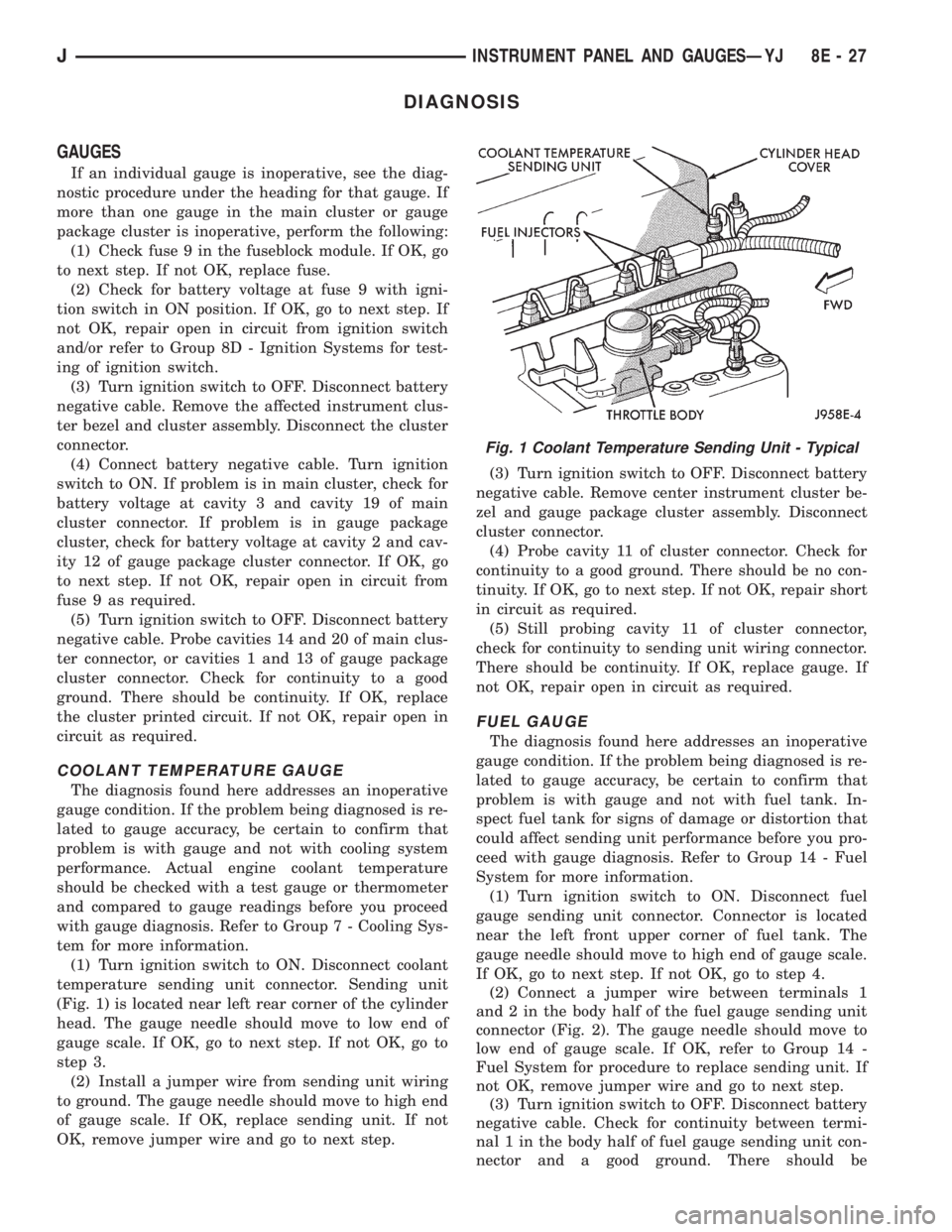
(1) Turn ignition switch to ON. Disconnect coolant
temperature sending unit connector. Sending unit
(Fig. 1) is located near left rear corner of the cylinder
head. The gauge needle should move to low end of
gauge scale. If OK, go to next step. If not OK, go to
step 3.
(2) Install a jumper wire from sending unit wiring
to ground. The gauge needle should move to high end
of gauge scale. If OK, replace sending unit. If not
OK, remove jumper wire and go to next step.(3) Turn ignition switch to OFF. Disconnect battery
negative cable. Remove center instrument cluster be-
zel and gauge package cluster assembly. Disconnect
cluster connector.
(4) Probe cavity 11 of cluster connector. Check for
continuity to a good ground. There should be no con-
tinuity. If OK, go to next step. If not OK, repair short
in circuit as required.
(5) Still probing cavity 11 of cluster connector,
check for continuity to sending unit wiring connector.
There should be continuity. If OK, replace gauge. If
not OK, repair open in circuit as required.
FUEL GAUGE
The diagnosis found here addresses an inoperative
gauge condition. If the problem being diagnosed is re-
lated to gauge accuracy, be certain to confirm that
problem is with gauge and not with fuel tank. In-
spect fuel tank for signs of damage or distortion that
could affect sending unit performance before you pro-
ceed with gauge diagnosis. Refer to Group 14 - Fuel
System for more information.
(1) Turn ignition switch to ON. Disconnect fuel
gauge sending unit connector. Connector is located
near the left front upper corner of fuel tank. The
gauge needle should move to high end of gauge scale.
If OK, go to next step. If not OK, go to step 4.
(2) Connect a jumper wire between terminals 1
and 2 in the body half of the fuel gauge sending unit
connector (Fig. 2). The gauge needle should move to
low end of gauge scale. If OK, refer to Group 14 -
Fuel System for procedure to replace sending unit. If
not OK, remove jumper wire and go to next step.
(3) Turn ignition switch to OFF. Disconnect battery
negative cable. Check for continuity between termi-
nal 1 in the body half of fuel gauge sending unit con-
nector and a good ground. There should be
Fig. 1 Coolant Temperature Sending Unit - Typical
JINSTRUMENT PANEL AND GAUGESÐYJ 8E - 27
Page 376 of 2198
(9) Turn ignition switch to START position and
hold there. Check for continuity between terminal for
circuit G11 of ignition switch and a good ground.
There should be continuity. If not OK, replace igni-
tion switch.
(10) Unplug brake warning switch connector.
Check for continuity between parking brake switch
connector and a good ground. There should be no
continuity. If OK, go to next step. If not OK, repair
short circuit as required.
(11) Check for continuity between parking brake
switch connector and brake warning switch connector
cavity for circuit G11. There should be continuity. If
OK, replace parking brake switch. If not OK, repair
open circuit to brake warning switch as required.
FOUR-WHEEL DRIVE INDICATOR LAMP
(1) Apply parking brake, start engine, vehicle in
4WD Lock or 4WD.
(2) Unplug switch and touch harness side of wire
to ground. Lamp should light. If OK, check switch
operation, replace if bad. If bulb is OK, repair open
to indicator.
HEADLAMP HIGH BEAM INDICATOR LAMP
(1) Check that headlamp high beams are func-
tional. If OK, go to next step. If not OK, refer to
Group 8L - Lamps for diagnosis of headlamp system.
(2) Disconnect battery negative cable. Remove left
instrument cluster bezel and main cluster assembly.
Unplug cluster connector. Connect battery negative
cable. Turn headlamps on and select high beam.
Check for battery voltage at cavity 17 of cluster con-
nector. If OK, replace indicator bulb. If not OK, re-
pair circuit to headlamp dimmer switch as required.
MALFUNCTION INDICATOR LAMP
The diagnosis found here addresses an inoperative
lamp condition. If the lamp comes on and stays on
with engine running, refer to Group 14 - Fuel System
for diagnosis. If no fuel or emission system problem
is found, the following procedure will help locate a
short or open in the lamp circuit.
(1) Disconnect battery negative cable. Unplug PCM
connector. Install a jumper wire from cavity 32 of
PCM connector (Fig. 5) to a good ground. Connect
battery negative cable. Turn ignition switch to ON.
Lamp should light. Remove jumper wire and lamp
should go OFF. If OK, refer to Powertrain Diagnostic
Procedures to check PCM. If not OK, go to next step.
(2) Turn ignition switch to OFF. Disconnect battery
negative cable. Remove left instrument cluster bezel
and main cluster assembly. Install a jumper wire
from cavity 2 of cluster connector to a good ground.
Connect battery negative cable. Turn ignition switch
to ON. Lamp should light. If OK, go to next step. If
not OK, replace bulb.(3) Turn ignition switch to OFF. Disconnect battery
negative cable. Unplug cluster connector. Check for
continuity between cavity 2 of cluster connector and
a good ground. There should be no continuity. If OK,
go to next step. If not OK, repair short circuit to
PCM as required.
(4) Check continuity between cavity 2 of cluster
connector and cavity 32 of PCM connector. There
should be continuity. If not OK, repair open circuit to
PCM as required.
SEAT BELT REMINDER LAMP
(1) Refer to Group 8U - Chime/Buzzer Warning
Systems to check chime/buzzer module operation. If
OK, go to next step. If not OK, replace chime/buzzer
module.
(2) Disconnect battery negative cable. Remove left
instrument cluster bezel and main cluster assembly.
Unplug cluster connector. Check for continuity be-
tween cavity 20 of cluster connector and a good
ground. There should be continuity. If OK, plug clus-
ter connector back into cluster and go to next step. If
not OK, repair open circuit to ground as required.
(3) Connect battery negative cable. Install a
jumper wire between a 12-volt battery feed and cav-
ity 16 of cluster connector. Lamp should light. If OK,
go to next step. If not OK, replace bulb.
(4) Disconnect battery negative cable. Unplug
chime/buzzer module from fuseblock module. Unplug
cluster connector. Check for continuity between cav-
ity 16 of cluster connector and a good ground. There
should be no continuity. If OK, go to next step. If not
OK, repair short circuit to chime/buzzer module as
required.
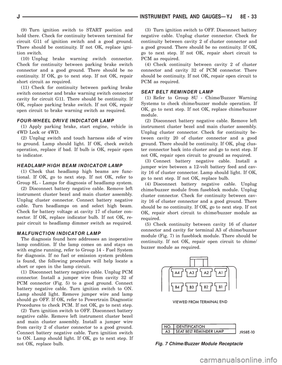
(5) Check continuity between cavity 16 of cluster
connector and cavity for terminal A3 of chime/buzzer
module (Fig. 7) in fuseblock module. There should be
continuity. If not OK, repair open circuit to chime/
buzzer module as required.
Fig. 7 Chime/Buzzer Module Receptacle
JINSTRUMENT PANEL AND GAUGESÐYJ 8E - 33
Page 377 of 2198
TURN SIGNAL INDICATOR LAMPS
(1) Disconnect battery negative cable. Remove left
instrument cluster bezel and main cluster assembly.
Probe cavity 20 of cluster connector. Check for conti-
nuity to a good ground. There should be continuity. If
OK, go to next step. If not OK, repair open circuit to
ground.
(2) Connect battery negative cable. Install a
jumper wire from cavity 18 (left indicator) or cavity 7
(right indicator) of cluster connector to a 12-volt bat-
tery feed. Lamp should light. If OK, continue to next
step. If not OK, replace bulb.
(3) Disconnect battery negative cable. Check for
continuity between cavity 18 (left indicator) or cavity
7 (right indicator) of cluster connector and cavity H
(left front turn signal) or cavity J (right front turn
signal) of steering column wiring connector. There
should be continuity. If OK, refer to Group 8J - Turn
Signal and Hazard Warning Systems for further di-
agnosis. If not OK, repair open circuit as required.
UPSHIFT INDICATOR LAMP
(1) Disconnect battery negative cable. Unplug PCM
connector. Connect battery negative cable. Turn igni-
tion switch to ON. Install a jumper wire from cavity
54 of PCM connector (Fig. 5) to a good ground. Lamp
should light. Remove jumper from ground. Lamp
should go off. If OK, refer to Powertrain Diagnostic
Procedures manual to diagnose PCM. If not OK, turn
ignition switch to OFF and go to next step.
(2) Disconnect battery negative cable. Remove left
instrument cluster bezel and main cluster assembly.
Install a jumper wire from cavity 5 of cluster connec-
tor to a good ground. Connect battery negative cable.
Turn ignition switch to ON. Lamp should light. If
OK, go to next step. If not OK, replace bulb.
(3) Turn ignition switch to OFF. Disconnect battery
negative cable. Unplug cluster connector. Check for
continuity between cavity 5 of cluster connector and
a good ground. There should be no continuity. If OK,
go to next step. If not OK, repair short circuit as re-
quired.(4) Check for continuity between cavity 5 of cluster
connector and cavity 54 of PCM connector. There
should be continuity. If not OK, repair open circuit as
required.
CLUSTER ILLUMINATION LAMPS
(1) Check fuse 10 in fuseblock module. If OK, go to
next step. If not OK, replace fuse.
(2) Turn park lamps on at headlamp switch. Rotate
panel dimmer switch thumb-wheel to HI position,
just before interior lamps detent. Check for battery
voltage at fuse 10 in fuseblock module. Rotate panel
dimmer thumb-wheel towards LO position while ob-
serving test voltmeter. Reading should go from bat-
tery voltage to zero volts. If OK, go to next step. If
not OK, repair open circuit to headlamp switch or re-
fer to Group 8L - Lamps to diagnose headlamp
switch.
(3) Disconnect battery negative cable. Remove left
or center instrument cluster bezel and main or gauge
package cluster assembly. Unplug cluster connector.
Connect battery negative cable. Turn park lamps on
at headlamp switch. Rotate panel dimmer thumb-
wheel to HI position, just before interior lamps de-
tent. Check for battery voltage at cavity 21 of main
cluster connector, or cavity 7 of gauge package clus-
ter connector. If OK, go to next step. If not OK, re-
pair open circuit to fuse as required.
(4) Turn park lamps off. Disconnect battery nega-
tive cable. Remove fuse 10 from fuseblock module.
Probe cavity 21 of main cluster connector, or cavity 7
of gauge package cluster connector. Check for conti-
nuity to a good ground. There should be no continu-
ity. If OK, go to next step. If not OK, repair short
circuit as required.
(5) Probe cavity 20 of main cluster connector, or
cavities 1 and 13 of gauge package cluster connector.
Check for continuity to ground. There should be con-
tinuity. If not OK, repair open circuit as required.
8E - 34 INSTRUMENT PANEL AND GAUGESÐYJJ
Page 389 of 2198
ANTENNA
All models use a fixed-length stainless steel rod-
type antenna mast, installed at the right front (fend-
er on XJ, cowl side on YJ) of the vehicle. The
antenna mast is connected to the center wire of the
coaxial antenna cable and is not grounded to any
part of the vehicle.
To eliminate static, the antenna base must have a
good ground. The coaxial antenna cable shield (the
outer wire mesh of the cable) is grounded to the an-
tenna base and the radio chassis.
The factory installed ETRs automatically compen-
sate for radio antenna trim. Therefore, no antenna
trimmer adjustment is required or possible when re-
placing the receiver or the antenna.
RADIO NOISE SUPPRESSION
Radio Frequency Interference (RFI) and Electro-
Magnetic Interference (EMI) noise suppression is ac-
complished primarily through circuitry internal to
the radio receivers. These internal suppression de-
vices are only serviced as a part of the radio receiver.External suppression devices that are serviceable
and should be checked in the case of RFI or EMI
noise complaints include the following:
²radio antenna base ground
²engine-to-body ground strap
²resistor-type spark plugs
²radio suppression-type secondary ignition wiring.
In addition, if the source of RFI or EMI noise is
identified as a component on the vehicle (i.e.:genera-
tor, blower motor, etc.), the ground path for that com-
ponent should be checked. If excessive resistance is
found in that circuit, repair as required before con-
sidering any component replacement.
Fleet vehicles are available with an extra-cost RFI-
suppressed Powertrain Control Module (PCM). This
unit reduces interference generated by the PCM on
some radio frequencies used in two-way radio com-
munications. However, this unit will not resolve com-
plaints of RFI in the commercial AM or FM radio
frequency ranges.
DIAGNOSIS
RADIO
CAUTION: Do not operate the radio with speaker
leads detached since damage to the transistors
may result.
(1) Check fuse 2 in fuseblock module and fuse in
back of radio chassis. If OK, go to next step. If not
OK, replace fuse.
(2) Turn ignition switch to ON position. Check for
battery voltage at fuse 2. If OK, go to next step. If
not OK, repair circuit to ignition switch as required.
(3) Turn ignition switch to OFF position. Discon-
nect battery negative cable. Remove instrument clus-
ter bezel. Remove radio, but do not unplug any
connections. Check for continuity between the radio
chassis and a good ground. There should be continu-
ity. If OK, go to next step. If not OK, repair radio
ground circuit as required.
(4) Connect battery negative cable. Turn ignition
switch to ON position. See Radio Connections chart.
Check for battery voltage at cavity 3 of radio connec-
tor. If OK, go to next step. If not OK, repair circuit to
fuse 2 as required.
(5) Turn ignition switch to OFF position. Check for
battery voltage at cavity 4 of radio connector. If OK,
replace radio. If not OK, repair circuit to IOD fuse in
PDC as required.
SPEAKERS
CAUTION: Do not operate the radio with speaker
leads detached since damage to the transistors
may result.
(1) Turn radio on and adjust balance and fader
controls to check performance of each individual
speaker. Note the speaker locations that are not per-
forming correctly. Go to next step.
(2) Turn radio off. Disconnect battery negative ca-
ble. Remove instrument cluster bezel and remove ra-
dio. See Radio Connections chart. Check both the
speaker feed and return cavities at radio for continu-
ity to a good ground. There should be no continuity.
If OK, go to next step. If not OK, repair wiring cir-
cuit as required.
(3) Check resistance between speaker feed and re-
turn cavities. Meter should read between 3 and 8
ohms (speaker impedance). If OK, see diagnosis for
Radio. If not OK, go to next step.
(4) Unplug speaker wiring connector. Check for
continuity between speaker feed cavity at radio and
at speaker. Repeat check between speaker return
cavity at radio and at speaker. If OK, replace
speaker. If not OK, repair wiring circuit as required.
8F - 2 AUDIO SYSTEMSJ
Page 399 of 2198
DIAGNOSIS
WARNING: ON VEHICLES EQUIPPED WITH AN AIR-
BAG, REFER TO GROUP 8M - RESTRAINT SYS-
TEMS BEFORE ATTEMPTING STEERING WHEEL
COMPONENT DIAGNOSIS OR SERVICE. FAILURE
TO TAKE PROPER PRECAUTIONS COULD RESULT
IN ACCIDENTAL AIRBAG DEPLOYMENT AND POS-
SIBLE PERSONAL INJURY.
(1) Inspect fuses (F8 and F16 in PDC on YJ)(11 in
fuseblock module and F14 in PDC on XJ). Replace
fuses, as required.
(2) Remove the horn relay (in the PDC on YJ)(in
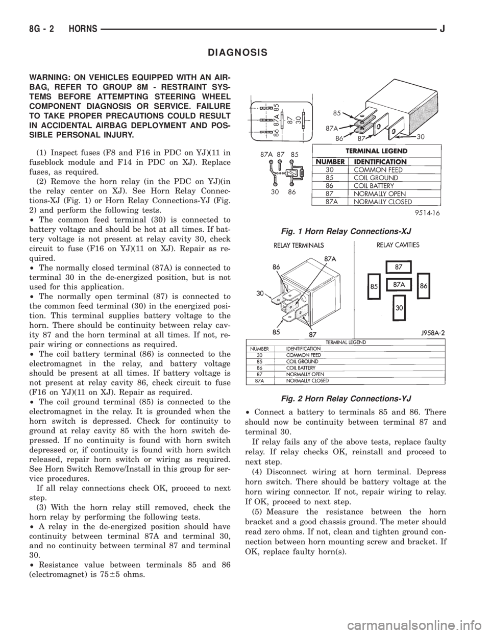
the relay center on XJ). See Horn Relay Connec-
tions-XJ (Fig. 1) or Horn Relay Connections-YJ (Fig.
2) and perform the following tests.
²The common feed terminal (30) is connected to
battery voltage and should be hot at all times. If bat-
tery voltage is not present at relay cavity 30, check
circuit to fuse (F16 on YJ)(11 on XJ). Repair as re-
quired.
²The normally closed terminal (87A) is connected to
terminal 30 in the de-energized position, but is not
used for this application.
²The normally open terminal (87) is connected to
the common feed terminal (30) in the energized posi-
tion. This terminal supplies battery voltage to the
horn. There should be continuity between relay cav-
ity 87 and the horn terminal at all times. If not, re-
pair wiring or connections as required.
²The coil battery terminal (86) is connected to the
electromagnet in the relay, and battery voltage
should be present at all times. If battery voltage is
not present at relay cavity 86, check circuit to fuse
(F16 on YJ)(11 on XJ). Repair as required.
²The coil ground terminal (85) is connected to the
electromagnet in the relay. It is grounded when the
horn switch is depressed. Check for continuity to
ground at relay cavity 85 with the horn switch de-
pressed. If no continuity is found with horn switch
depressed or, if continuity is found with horn switch
released, repair horn switch or wiring as required.
See Horn Switch Remove/Install in this group for ser-
vice procedures.
If all relay connections check OK, proceed to next
step.
(3) With the horn relay still removed, check the
horn relay by performing the following tests.
²A relay in the de-energized position should have
continuity between terminal 87A and terminal 30,
and no continuity between terminal 87 and terminal
30.
²Resistance value between terminals 85 and 86
(electromagnet) is 7565 ohms.²Connect a battery to terminals 85 and 86. There
should now be continuity between terminal 87 and
terminal 30.
If relay fails any of the above tests, replace faulty
relay. If relay checks OK, reinstall and proceed to
next step.
(4) Disconnect wiring at horn terminal. Depress
horn switch. There should be battery voltage at the
horn wiring connector. If not, repair wiring to relay.
If OK, proceed to next step.
(5) Measure the resistance between the horn
bracket and a good chassis ground. The meter should
read zero ohms. If not, clean and tighten ground con-
nection between horn mounting screw and bracket. If
OK, replace faulty horn(s).
Fig. 1 Horn Relay Connections-XJ
Fig. 2 Horn Relay Connections-YJ
8G - 2 HORNSJ
Page 414 of 2198
TURN SIGNAL AND HAZARD WARNING SYSTEMS
CONTENTS
page page
DIAGNOSIS............................. 3
GENERAL INFORMATION.................. 1SERVICE PROCEDURES................... 5
GENERAL INFORMATION
Following are general descriptions of the major
components in the XJ (Cherokee)/YJ (Wrangler)
model turn signal and hazard warning systems. Refer
to Group 8W - Wiring Diagrams for complete circuit
descriptions and diagrams.
TURN SIGNAL SYSTEM
With the ignition switch in the ON or ACCESSORY
position and the turn signal switch lever (YJ) or
multi-function switch control lever (XJ) moved up
(right turn) or down (left turn), the turn signal sys-
tem is activated.
When the turn signal system is activated, the se-
lected (right or left) turn signal indicator lamp, front
park/turn signal lamp and rear tail/stop/turn signal
lamp bulb filaments will flash. With the headlamp
switch in the OFF position, the turn and front side
marker lamps flash in unison. With the headlamp
switch in the ON position, the turn and front side
marker lamps flash alternately.
HAZARD WARNING SYSTEM
The hazard warning is activated by a switch button
located below the ignition lock cylinder (YJ) or on the
top of the steering column (XJ) between the steering
wheel and the instrument panel. The hazard warning
flasher (YJ) or combination flasher (XJ) receives bat-
tery feed at all times, and the system is functional
regardless of ignition switch position. The hazard
warning switch button is identified with a double
triangle. On YJ models, push the switch button in to
activate the hazard warning system and pull the
button out to turn system off. On XJ models, push in
on the switch button to latch the switch and activate
the hazard warning system, and push in on the
switch button again to unlatch the switch and turn
the system off.
When the hazard warning system is activated, all
(right and left) turn signal indicator, front park/turn
signal lamp and rear tail/stop/turn signal lamp bulb
filaments will flash.
TURN SIGNAL FLASHER (YJ ONLY)
The turn signal flasher is located in the fuseblock
module. It contains one fixed contact point and one
contact point attached to a flexible bimetal arm. The
contact points are normally closed. When a turn sig-
nal is activated, current flows through the flasher. As
current flows through the bimetal arm it heats and
flexes to pull the contact points open, stopping cur-
rent flow. As the bimetal arm cools it straightens,
until the contact points close and the cycle repeats.
The standard flasher is designed to handle the cur-
rent flow requirements of the factory installed light-
ing. If supplemental lighting is added to the turn
signal circuits such as when towing a trailer with
lights, the current flow through the flasher increases.
This causes the flash rate to increase. It is recom-
mended that the standard flasher be replaced with a
heavy-duty (hazard warning) flasher when supple-
mental lighting is added.
However, when a turn signal bulb fails with a stan-
dard flasher, the remaining bulbs in that circuit will
light, but not flash. This will give the driver an indi-
cation to check the turn signal bulbs. Because a
heavy-duty flasher has different internal circuitry, a
failed bulb will not prevent the remaining bulbs in
the circuit from flashing. Therefore, it is recom-
mended that an occasional visual inspection of exte-
rior turn signal lamp operation be performed when a
heavy-duty flasher is installed.
HAZARD WARNING FLASHER (YJ ONLY)
The hazard warning flasher is located in the fuse-
block module. The hazard warning flasher contains
two normally open contact points mounted to two
flexible arms. A bimetal strip is attached between the
two arms. When the hazard warning is activated,
current flows through the flasher. As the current
flows through the bimetal strip it heats and pulls the
flexible arms together until the contact points close,
JTURN SIGNAL AND HAZARD WARNING SYSTEMS 8J - 1
Page 416 of 2198
DIAGNOSIS
When diagnosing the turn signal or hazard warning
circuits, remember that high generator output can
burn out bulbs rapidly and repeatedly. If this is a
problem on the vehicle being diagnosed, refer to
Group 8A - Battery/Starting/Charging Systems Diag-
nostics to test charging system.
WARNING: ON VEHICLES EQUIPPED WITH AN AIR-
BAG, REFER TO GROUP 8M - RESTRAINT SYS-
TEMS BEFORE ATTEMPTING STEERING WHEEL
COMPONENT DIAGNOSIS OR SERVICE. FAILURE
TO TAKE PROPER PRECAUTIONS COULD RESULT
IN ACCIDENTAL AIRBAG DEPLOYMENT AND POS-
SIBLE PERSONAL INJURY.
TURN SIGNAL/HAZARD WARNING SYSTEM - XJ
(1) Turn ignition switch to ON position. Actuate the
turn signal lever or hazard warning button. Observe
the turn indicator lamp(s) in the instrument cluster.
If the flash rate is very high, check for a turn signal
bulb that is not lit. Replace that bulb or repair cir-
cuits to that lamp, as required. Test operation. If turn
indicator does not light, continue to next step.
(2) Remove and inspect fuse 8 (turn signals) in
fuseblock module, or fuse F13 (hazard warning) in the
Power Distribution Center. Replace fuse, if required.
(3) Remove combination flasher from relay center
and replace with a known good unit. Test operation of
turn signal and hazard warning systems. If OK, re-place faulty combination flasher. If not OK, remove
test flasher and go to next step.
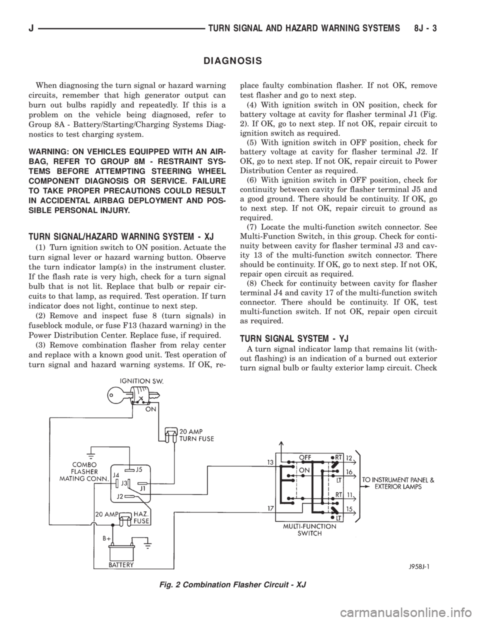
(4) With ignition switch in ON position, check for
battery voltage at cavity for flasher terminal J1 (Fig.
2). If OK, go to next step. If not OK, repair circuit to
ignition switch as required.
(5) With ignition switch in OFF position, check for
battery voltage at cavity for flasher terminal J2. If
OK, go to next step. If not OK, repair circuit to Power
Distribution Center as required.
(6) With ignition switch in OFF position, check for
continuity between cavity for flasher terminal J5 and
a good ground. There should be continuity. If OK, go
to next step. If not OK, repair circuit to ground as
required.
(7) Locate the multi-function switch connector. See
Multi-Function Switch, in this group. Check for conti-
nuity between cavity for flasher terminal J3 and cav-
ity 13 of the multi-function switch connector. There
should be continuity. If OK, go to next step. If not OK,
repair open circuit as required.
(8) Check for continuity between cavity for flasher
terminal J4 and cavity 17 of the multi-function switch
connector. There should be continuity. If OK, test
multi-function switch. If not OK, repair open circuit
as required.
TURN SIGNAL SYSTEM - YJ
A turn signal indicator lamp that remains lit (with-
out flashing) is an indication of a burned out exterior
turn signal bulb or faulty exterior lamp circuit. Check
Fig. 2 Combination Flasher Circuit - XJ
JTURN SIGNAL AND HAZARD WARNING SYSTEMS 8J - 3