1995 JEEP CHEROKEE turn signal bulb
[x] Cancel search: turn signal bulbPage 459 of 2198
BACK-UP/REAR TURN SIGNAL/TAIL LAMP BULB
REPLACEMENTÐXJ
REMOVAL
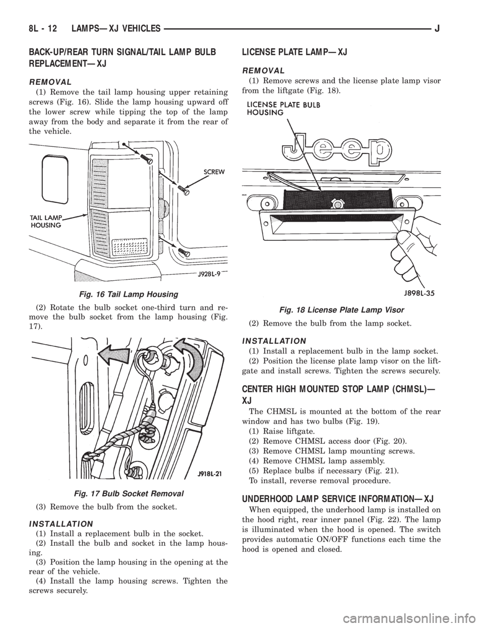
(1) Remove the tail lamp housing upper retaining
screws (Fig. 16). Slide the lamp housing upward off
the lower screw while tipping the top of the lamp
away from the body and separate it from the rear of
the vehicle.
(2) Rotate the bulb socket one-third turn and re-
move the bulb socket from the lamp housing (Fig.
17).
(3) Remove the bulb from the socket.
INSTALLATION
(1) Install a replacement bulb in the socket.
(2) Install the bulb and socket in the lamp hous-
ing.
(3) Position the lamp housing in the opening at the
rear of the vehicle.
(4) Install the lamp housing screws. Tighten the
screws securely.
LICENSE PLATE LAMPÐXJ
REMOVAL
(1) Remove screws and the license plate lamp visor
from the liftgate (Fig. 18).
(2) Remove the bulb from the lamp socket.
INSTALLATION
(1) Install a replacement bulb in the lamp socket.
(2) Position the license plate lamp visor on the lift-
gate and install screws. Tighten the screws securely.
CENTER HIGH MOUNTED STOP LAMP (CHMSL)Ð
XJ
The CHMSL is mounted at the bottom of the rear
window and has two bulbs (Fig. 19).
(1) Raise liftgate.
(2) Remove CHMSL access door (Fig. 20).
(3) Remove CHMSL lamp mounting screws.
(4) Remove CHMSL lamp assembly.
(5) Replace bulbs if necessary (Fig. 21).
To install, reverse removal procedure.
UNDERHOOD LAMP SERVICE INFORMATIONÐXJ
When equipped, the underhood lamp is installed on
the hood right, rear inner panel (Fig. 22). The lamp
is illuminated when the hood is opened. The switch
provides automatic ON/OFF functions each time the
hood is opened and closed.
Fig. 16 Tail Lamp Housing
Fig. 17 Bulb Socket Removal
Fig. 18 License Plate Lamp Visor
8L - 12 LAMPSÐXJ VEHICLESJ
Page 465 of 2198
BULB APPLICATIONÐXJ VEHICLES
GENERAL INFORMATION
The following Bulb Application Table lists the lamp
title on the left side of the column and trade number
or part number on the right.
CAUTION: Do not use bulbs that have a higher can-
dle power than the bulb listed in the Bulb Applica-
tion Table. Damage to lamp can result.
Do not touch halogen bulbs with fingers or other
oily surfaces. Bulb life will be reduced.
EXTERIOR LAMPSÐXJ
Back-up .................................................................1156
Center High Mounted Stoplamp ..........................922
Fog ............................................................................H3
Front Side Marker .................................................194
Headlamp/Sealed Beam....................................H6054
License Plate ..........................................................168
License Plate W/Outside Spare ..............................67
Park/Turn Signal ............................................2057NA
Tail/Stop ................................................................2057
Turn Signal ...........................................................1156
INTERIOR LAMPSÐXJ
Service procedures for most of the lamps in the in-
strument panel, Instrument cluster and switches are
located in Group 8E, Instrument Panel and Gauges.
Some components have lamps that can only be ser-
viced by an Authorized Service Center (ASC) after
the component is removed from the vehicle. Contact
local dealer for location of nearest ASC.
Cargo .......................................................................561
Dome .......................................................................561
Dome/Reading.........................................................906Glove Compartment ...............................................194
Overhead Console ..................................................912
Under Hood ............................................................105
Vanity Mirror ...........................................................74
Underpanel Courtesy.............................................168
INDICATOR LAMPS
Service procedures for most of the lamps in the in-
strument panel, instrument cluster and switches are
located in Group 8E, Instrument Panel and Gauges.
A/C Control ...............................................................74
Airbag ........................................................................74
Anti-lock Brake ........................................................74
Ash Receiver .........................................................1891
Brake Warning .........................................................74
Check Engine ...........................................................74
Cigar Lighter ............................................................53
Diesel Wait ...............................................................74
Fasten Seat Belts ....................................................74
Four Wheel Drive ....................................................74
Generator ................................................................194
Generator/Diesel.......................................................74
Heater Control .........................................................74
High Beam..............................................................194
Illumination ............................................................194
Low Fuel .................................................................194
Low Washer Fluid....................................................74
Radio ......................................................................ASC
Rocker Switch...........................................................37
Seat Belt ...................................................................74
Transfer Case .........................................................658
Transmission Floor Shift.......................................658
Turn Signal.............................................................194
Shift ...........................................................................74
Water In Fuel ...........................................................74
8L - 18 LAMPSÐXJ VEHICLESJ
Page 469 of 2198
SERVICE PROCEDURES
INDEX
page page
Back-Up/Rear Turn Signal/Tail Lamp Bulb
ReplacementÐYJ....................... 28
Center High Mounted Stop Lamp (CHMSL)ÐYJ . . 28
Daytime Running Lights (Canada Only)ÐYJ..... 30
Drl Module ReplacementÐYJ................ 30
Fog Lamp ReplacementÐYJ................. 25
Fog Lamp Switch ReplacementÐYJ........... 26
Fog LampsÐYJ.......................... 23
Front Park/Turn Signal Lamp Bulb ReplacementÐ
YJ ................................... 25
Headlamp Alignment PreparationÐYJ.......... 22Headlamp AlignmentÐYJ................... 22
Headlamp Bulb ReplacementÐYJ............. 23
Headlamp Dimmer Switch ReplacementÐYJ..... 26
Headlamp SwitchÐYJ...................... 26
Headlamp/Fog Lamp Adjustment Using Alignment
ScreenÐYJ............................ 23
Side Marker Lamp Bulb ReplacementÐYJ....... 25
Underhood Lamp Bulb ReplacementÐYJ....... 29
Underhood Lamp ReplacementÐYJ........... 29
Underhood Lamp Service InformationÐYJ....... 28
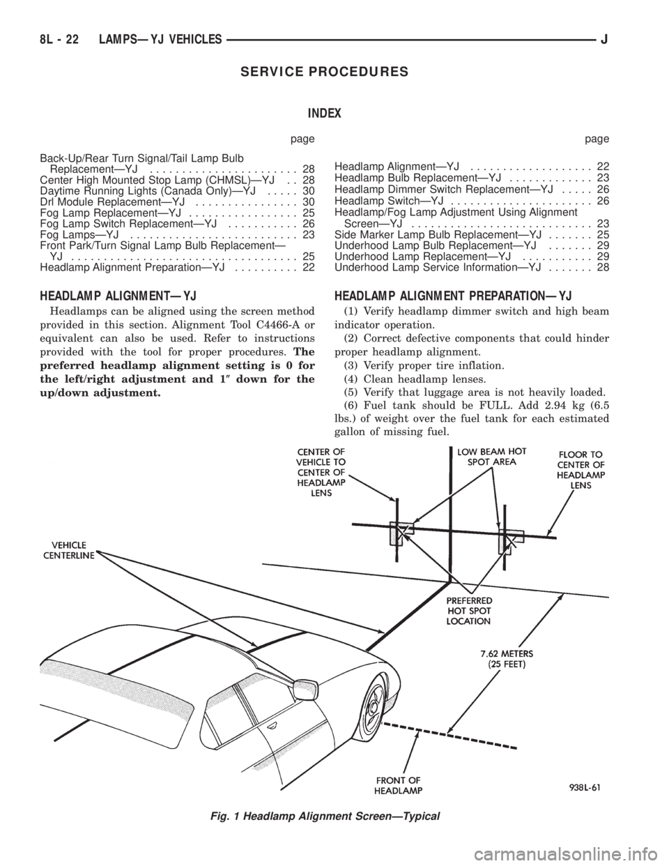
HEADLAMP ALIGNMENTÐYJ
Headlamps can be aligned using the screen method
provided in this section. Alignment Tool C4466-A or
equivalent can also be used. Refer to instructions
provided with the tool for proper procedures.The
preferred headlamp alignment setting is 0 for
the left/right adjustment and 1(down for the
up/down adjustment.
HEADLAMP ALIGNMENT PREPARATIONÐYJ
(1) Verify headlamp dimmer switch and high beam
indicator operation.
(2) Correct defective components that could hinder
proper headlamp alignment.
(3) Verify proper tire inflation.
(4) Clean headlamp lenses.
(5) Verify that luggage area is not heavily loaded.
(6) Fuel tank should be FULL. Add 2.94 kg (6.5
lbs.) of weight over the fuel tank for each estimated
gallon of missing fuel.
Fig. 1 Headlamp Alignment ScreenÐTypical
8L - 22 LAMPSÐYJ VEHICLESJ
Page 472 of 2198
FOG LAMP REPLACEMENTÐYJ
REMOVAL
(1) Disconnect the fog lamp wire harness connec-
tor.
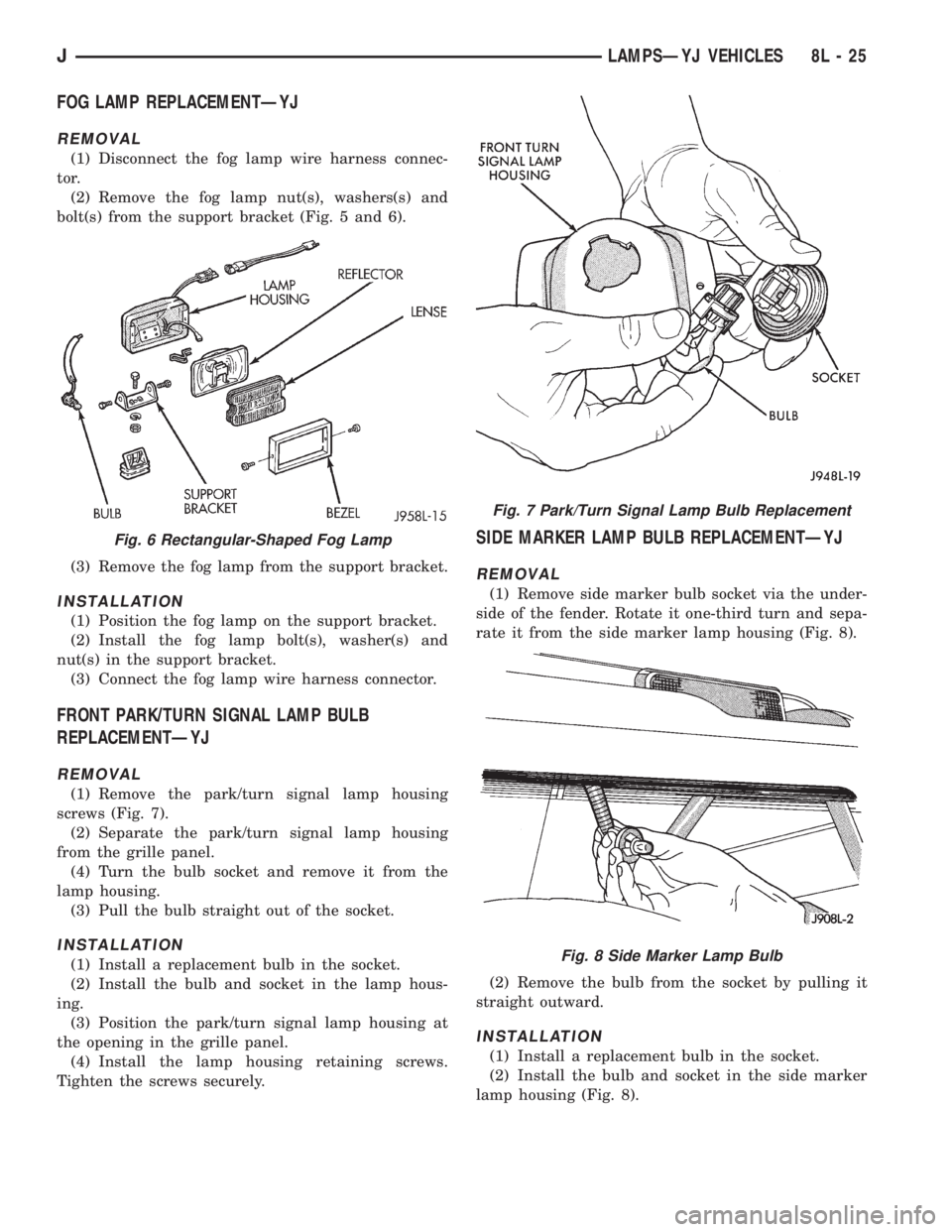
(2) Remove the fog lamp nut(s), washers(s) and
bolt(s) from the support bracket (Fig. 5 and 6).
(3) Remove the fog lamp from the support bracket.
INSTALLATION
(1) Position the fog lamp on the support bracket.
(2) Install the fog lamp bolt(s), washer(s) and
nut(s) in the support bracket.
(3) Connect the fog lamp wire harness connector.
FRONT PARK/TURN SIGNAL LAMP BULB
REPLACEMENTÐYJ
REMOVAL
(1) Remove the park/turn signal lamp housing
screws (Fig. 7).
(2) Separate the park/turn signal lamp housing
from the grille panel.
(4) Turn the bulb socket and remove it from the
lamp housing.
(3) Pull the bulb straight out of the socket.
INSTALLATION
(1) Install a replacement bulb in the socket.
(2) Install the bulb and socket in the lamp hous-
ing.
(3) Position the park/turn signal lamp housing at
the opening in the grille panel.
(4) Install the lamp housing retaining screws.
Tighten the screws securely.
SIDE MARKER LAMP BULB REPLACEMENTÐYJ
REMOVAL
(1) Remove side marker bulb socket via the under-
side of the fender. Rotate it one-third turn and sepa-
rate it from the side marker lamp housing (Fig. 8).
(2) Remove the bulb from the socket by pulling it
straight outward.
INSTALLATION
(1) Install a replacement bulb in the socket.
(2) Install the bulb and socket in the side marker
lamp housing (Fig. 8).
Fig. 6 Rectangular-Shaped Fog Lamp
Fig. 7 Park/Turn Signal Lamp Bulb Replacement
Fig. 8 Side Marker Lamp Bulb
JLAMPSÐYJ VEHICLES 8L - 25
Page 475 of 2198
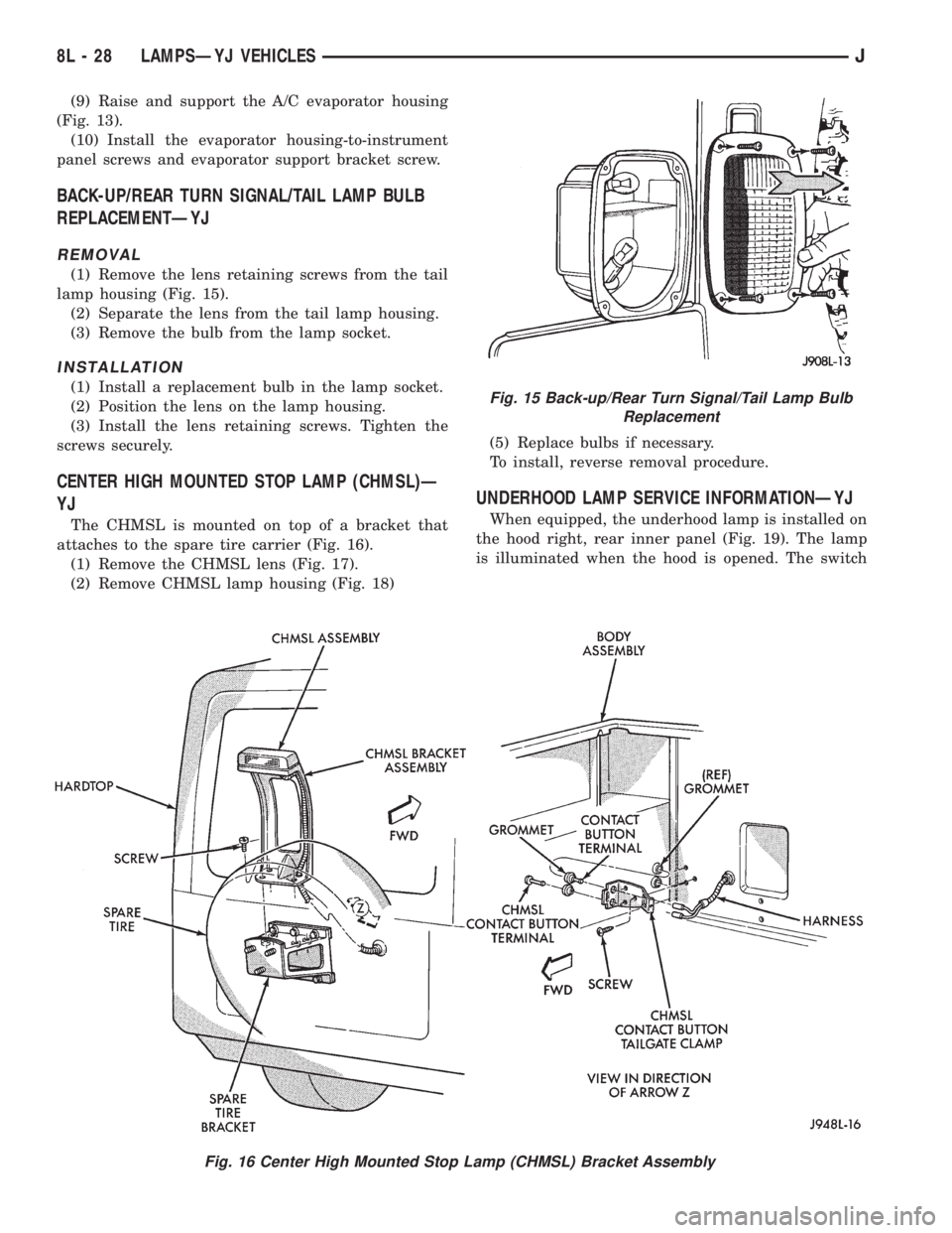
(9) Raise and support the A/C evaporator housing
(Fig. 13).
(10) Install the evaporator housing-to-instrument
panel screws and evaporator support bracket screw.
BACK-UP/REAR TURN SIGNAL/TAIL LAMP BULB
REPLACEMENTÐYJ
REMOVAL
(1) Remove the lens retaining screws from the tail
lamp housing (Fig. 15).
(2) Separate the lens from the tail lamp housing.
(3) Remove the bulb from the lamp socket.
INSTALLATION
(1) Install a replacement bulb in the lamp socket.
(2) Position the lens on the lamp housing.
(3) Install the lens retaining screws. Tighten the
screws securely.
CENTER HIGH MOUNTED STOP LAMP (CHMSL)Ð
YJ
The CHMSL is mounted on top of a bracket that
attaches to the spare tire carrier (Fig. 16).
(1) Remove the CHMSL lens (Fig. 17).
(2) Remove CHMSL lamp housing (Fig. 18)(5) Replace bulbs if necessary.
To install, reverse removal procedure.
UNDERHOOD LAMP SERVICE INFORMATIONÐYJ
When equipped, the underhood lamp is installed on
the hood right, rear inner panel (Fig. 19). The lamp
is illuminated when the hood is opened. The switch
Fig. 15 Back-up/Rear Turn Signal/Tail Lamp Bulb
Replacement
Fig. 16 Center High Mounted Stop Lamp (CHMSL) Bracket Assembly
8L - 28 LAMPSÐYJ VEHICLESJ
Page 477 of 2198
(3) Insert a replacement bulb in the lamp base
socket and rotate it clockwise.
(4) Connect the wire harness connector to the
lamp.
DAYTIME RUNNING LIGHTS (CANADA ONLY)ÐYJ
The Daytime Running Lights (Headlamps) System
is installed on vehicles manufactured for sale in Can-
ada only. The headlamps are illuminated when the
ignition switch is turned to the ON position. The
DRL module receives a vehicle-moving signal from
the vehicle speed sensor. This provides a constant
headlamps-oncondition as long as the vehicle is
moving. The lamps are illuminated at less than 50
percent of normal intensity.
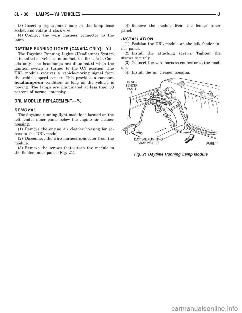
DRL MODULE REPLACEMENTÐYJ
REMOVAL
The daytime running light module is located on the
left fender inner panel below the engine air cleaner
housing.
(1) Remove the engine air cleaner housing for ac-
cess to the DRL module.
(2) Disconnect the wire harness connector from the
module.
(3) Remove the screws that attach the module to
the fender inner panel (Fig. 21).(4) Remove the module from the fender inner
panel.
INSTALLATION
(1) Position the DRL module on the left, fender in-
ner panel.
(2) Install the attaching screws. Tighten the
screws securely.
(3) Connect the wire harness connector to the mod-
ule.
(4) Install the air cleaner housing.
Fig. 21 Daytime Running Lamp Module
8L - 30 LAMPSÐYJ VEHICLESJ
Page 479 of 2198

BULB APPLICATIONÐYJ VEHICLES
GENERAL INFORMATION
The following Bulb Application Table lists the lamp
title on the left side of the column and trade number
or part number on the right.
CAUTION: Do not use bulbs that have a higher can-
dle power than the bulb listed in the Bulb Applica-
tion Table. Damage to lamp can result.
Do not touch halogen bulbs with fingers or other
oily surfaces. Bulb life will be reduced.
EXTERIOR LAMPSÐYJ
Back-up .................................................................1156
Center High Mounted Stoplamp ..........................912
Fog ............................................................................H3
Front Side Marker .................................................194
Headlamp/Sealed Beam....................................H6054
Park/Turn Signal..................................................3157
Tail/Stop ................................................................1157
INTERIOR LAMPSÐYJ
Service procedures for most of the lamps in the in-
strument panel, Instrument cluster and switches are
located in Group 8E, Instrument Panel and Gauges.
Some components have lamps that can only be ser-
viced by an Authorized Service Center (ASC) after
the component is removed from the vehicle. Contact
local dealer for location of nearest ASC.Dome/Cargo .........................................................212-2
Glove Compartment ...............................................194
Under Hood ............................................................105
Underpanel Courtesy...............................................89
INDICATOR LAMPS
Service procedures for most of the lamps in the in-
strument panel, instrument cluster and switches are
located in Group 8E, Instrument Panel and Gauges.
A/C Control ...............................................................74
Anti-lock Brake ........................................................74
Ash Receiver .........................................................1891
Brake Warning .........................................................74
Cigar Lighter ............................................................53
Fasten Seat Belts ....................................................74
Four Wheel Drive ....................................................74
Generator ................................................................194
Hazard.......................................................................74
Heater Control .......................................................194
High Beam..............................................................194
Illumination ............................................................194
Low Coolant..............................................................74
Radio ......................................................................ASC
Rocker Switch...........................................................74
Seat Belt ...................................................................74
Shift ...........................................................................74
Turn Signal.............................................................194
8L - 32 LAMPSÐYJ VEHICLESJ
Page 612 of 2198
INSTRUMENT CLUSTER
INDEX
page page
ABS Warning Lamp........................ 2
Brake Warning Lamp....................... 2
Charging System Indicator Lamp............... 3
Cluster Ground............................ 3
Diagram Index............................. 3
Engine Coolant Temperature Gauge............ 1
Engine Coolant Temperature Warning Lamp...... 1
Fuel Gauge.............................. 1
High-Beam Indicator Lamp................... 2
Instrument Cluster......................... 1Low Fuel Warning Lamp..................... 1
Low Washer Fluid Warning Lamp.............. 2
Malfunction Indicator Lamp (MIL)............... 2
Manual Transmission Up-Shift Lamp............ 2
Oil Pressure Gauge........................ 2
Oil Pressure Warning Lamp.................. 2
Seat Belt Indicator Warning Lamp.............. 2
Speedometer............................. 2
Tachometer.............................. 2
Turn Signal Indicator Lamps.................. 2
INSTRUMENT CLUSTER
The instrument cluster contains the gauges and
warning lamps. All gauges have magnetic move-
ments.
When the ignition switch is in the START or RUN
position, circuit A21 feeds circuit F87 through fuse 17
in the fuse block. Circuit A1 from fuse 6 in the Power
Distribution Center (PDC) supplies voltage to circuit
A21. Circuit A1 is HOT at all times.
Circuit F87 connects to the cluster connector to
power the gauges and to the telltale connector to
power the warning lamps.
Circuit E2 from fuse 19 in the fuse block feeds the
illumination lamps. Circuit E2 originates at the head-
lamp switch and continues through fuse 19. The
headlamp switch powers circuit E2 when the parking
lamps or headlamp are ON.
Circuit Z2 provides ground for the indicator lamps
and illumination lamps.
ENGINE COOLANT TEMPERATURE GAUGE
Circuit G20 connects the engine coolant tempera-
ture gauge to the engine coolant temperature sensor.
The sensor is a variable resistor and case grounded to
the engine. Circuit F87 connects to the instrument
cluster left connector and supplies voltage for the
gauge.
The gauge uses two coils. Current passing through
the coils creates a magnetic field. Position of the
gauge needle is controlled by the amount of current
passing through the coils to ground at the sensor.
ENGINE COOLANT TEMPERATURE WARNING
LAMP
Circuit G20 connects the engine coolant tempera-
ture warning lamp to the engine coolant temperature
switch. When the switch closes, battery voltage from
circuit F87 flows through the lamp to ground through
the switch on circuit G20. The engine coolant tem-
perature switch is case grounded to the engine. Cir-cuit F87 connects to the instrument cluster connector
and supplies voltage for the lamp.
Circuit G20 also connects to the warning lamp to
ground when the ignition switch is in the START
position. When the ignition switch is in the START
position, the lamp illuminates for a bulb test.
FUEL GAUGE
The fuel level sensor is a variable resistor. Circuit
G4 connects the fuel level sensor to the fuel gauge in
the instrument cluster. Circuit F87 from fuse 17 in
the fuse block supplies voltage to the fuel gauge. The
fuel level sensor draws voltage from circuit F87
through the fuel gauge on circuit G4. Circuit G4
connects to circuit 57 in the fuel pump module har-
ness. Circuit 57 connects to the fuel level sensor.
Circuit 99 in the fuel pump module harness con-
nects to circuit Z1. Circuit Z1 provides the ground
path for the fuel level sensor. The grounding point for
circuit Z1 is the left side of the cowl panel.
As current flows through the coils in the fuel gauge,
it creates a magnetic field. One of the coils in the
gauge receives fixed current. The other coil is con-
nected to the level sensor. The magnetic field controls
the position of the fuel gauge pointer.
The fuel level sensor contains a variable resistor. As
the position of the float arm on the fuel level sensor
changes, the resistor changes the current flow
through second coil in the fuel gauge. A change in
current flow alters the magnetic field in the fuel
gauge, which changes the pointer position.
LOW FUEL WARNING LAMP
Circuit G4 connects the fuel level sensor to the fuel
gauge. The low fuel level module at the rear of the
gauge monitors resistance in circuit G4. The low fuel
level module powers an light emitting diode (LED)
when the resistance in circuit G4 reaches a calibrated
level. The LED illuminates the Low Fuel indicator.
Refer to Group 8E for additional information.
J8W-40 INSTRUMENT CLUSTERÐXJ VEHICLES 8W - 40 - 1