1995 JEEP CHEROKEE fuel
[x] Cancel search: fuelPage 293 of 2198
USING ON-BOARD DIAGNOSTIC SYSTEM
GENERAL INFORMATION
The Powertrain Control Module (PCM) monitors
critical input and output circuits of the charging sys-
tem, making sure they are operational. A Diagnostic
Trouble Code (DTC) is assigned to each input and
output circuit monitored by the OBD system. Some
circuits are checked continuously and some are
checked only under certain conditions.
If the OBD system senses that a monitored circuit
is bad, it will put a DTC into electronic memory. The
DTC will stay in electronic memory as long as the
circuit continues to be bad. The PCM is programmed
to clear the memory after 50 engine starts, if the
problem does not occur again.
DIAGNOSTIC TROUBLE CODES
Diagnostic Trouble Codes (DTC) are two-digit num-
bers flashed on the malfunction indicator (Check En-
gine) lamp that identify which circuit is bad. A DTC
description can also be read using the DRB scan tool.
Refer to Group 14 - Fuel Systems for more informa-
tion.
A DTC does not identify which component in a cir-
cuit is bad. Thus, a DTC should be treated as a
symptom, not as the cause for the problem. In some
cases, because of the design of the diagnostic test
procedure, a DTC can be the reason for another DTCto be set. Therefore, it is important that the test pro-
cedures be followed in sequence, to understand what
caused a DTC to be set.
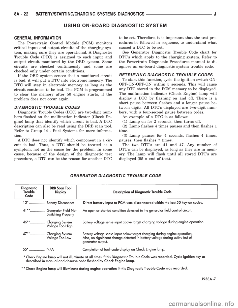
See Generator Diagnostic Trouble Code chart for
DTC's which apply to the charging system. Refer to
the Powertrain Diagnostic Procedures manual to di-
agnose an on-board diagnostic system trouble code.
RETRIEVING DIAGNOSTIC TROUBLE CODES
To start this function, cycle the ignition switch ON-
OFF-ON-OFF-ON within 5 seconds. This will cause
any DTC stored in the PCM memory to be displayed.
The malfunction indicator (Check Engine) lamp will
display a DTC by flashing on and off. There is a
short pause between flashes and a longer pause be-
tween digits. All DTC's displayed are two-digit num-
bers, with a four-second pause between codes.
An example of a DTC is as follows:
(1) Lamp on for 2 seconds, then turns off.
(2) Lamp flashes 4 times pauses and then flashes 1
time.
(3) Lamp pauses for 4 seconds, flashes 4 times,
pauses, then flashes 7 times.
The two DTC's are 41 and 47. Any number of
DTC's can be displayed, as long as they are in mem-
ory. The lamp will flash until all stored DTC's are
displayed (55 = end of test).
GENERATOR DIAGNOSTIC TROUBLE CODE
8A - 22 BATTERY/STARTING/CHARGING SYSTEMS DIAGNOSTICSJ
Page 301 of 2198
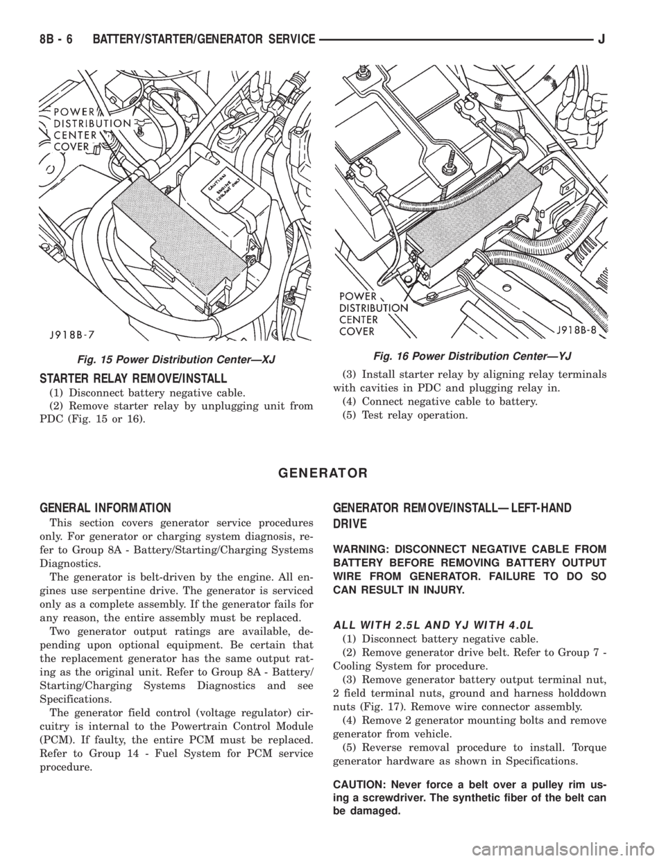
STARTER RELAY REMOVE/INSTALL
(1) Disconnect battery negative cable.
(2) Remove starter relay by unplugging unit from
PDC (Fig. 15 or 16).(3) Install starter relay by aligning relay terminals
with cavities in PDC and plugging relay in.
(4) Connect negative cable to battery.
(5) Test relay operation.
GENERATOR
GENERAL INFORMATION
This section covers generator service procedures
only. For generator or charging system diagnosis, re-
fer to Group 8A - Battery/Starting/Charging Systems
Diagnostics.
The generator is belt-driven by the engine. All en-
gines use serpentine drive. The generator is serviced
only as a complete assembly. If the generator fails for
any reason, the entire assembly must be replaced.
Two generator output ratings are available, de-
pending upon optional equipment. Be certain that
the replacement generator has the same output rat-
ing as the original unit. Refer to Group 8A - Battery/
Starting/Charging Systems Diagnostics and see
Specifications.
The generator field control (voltage regulator) cir-
cuitry is internal to the Powertrain Control Module
(PCM). If faulty, the entire PCM must be replaced.
Refer to Group 14 - Fuel System for PCM service
procedure.
GENERATOR REMOVE/INSTALLÐLEFT-HAND
DRIVE
WARNING: DISCONNECT NEGATIVE CABLE FROM
BATTERY BEFORE REMOVING BATTERY OUTPUT
WIRE FROM GENERATOR. FAILURE TO DO SO
CAN RESULT IN INJURY.
ALL WITH 2.5L AND YJ WITH 4.0L
(1) Disconnect battery negative cable.
(2) Remove generator drive belt. Refer to Group 7 -
Cooling System for procedure.
(3) Remove generator battery output terminal nut,
2 field terminal nuts, ground and harness holddown
nuts (Fig. 17). Remove wire connector assembly.
(4) Remove 2 generator mounting bolts and remove
generator from vehicle.
(5) Reverse removal procedure to install. Torque
generator hardware as shown in Specifications.
CAUTION: Never force a belt over a pulley rim us-
ing a screwdriver. The synthetic fiber of the belt can
be damaged.
Fig. 15 Power Distribution CenterÐXJFig. 16 Power Distribution CenterÐYJ
8B - 6 BATTERY/STARTER/GENERATOR SERVICEJ
Page 312 of 2198
IGNITION SYSTEMS
CONTENTS
page page
COMPONENT IDENTIFICATION/SYSTEM
OPERATION........................... 1
COMPONENT REMOVAL/INSTALLATION...... 17
DIAGNOSTICS/SERVICE PROCEDURES....... 6IGNITION SWITCHÐXJ MODELS........... 26
IGNITION SWITCHÐYJ MODELS........... 29
SPECIFICATIONS........................ 32
COMPONENT IDENTIFICATION/SYSTEM OPERATION
INDEX
page page
Automatic Shutdown (ASD) Relay.............. 1
Camshaft Position Sensor.................... 2
Crankshaft Position Sensor................... 3
Distributors............................... 4
Engine Coolant Temperature Sensor............ 5
General Information........................ 1Ignition Coil.............................. 4
Intake Manifold Air Temperature Sensor.......... 5
Manifold Absolute Pressure (MAP) Sensor........ 5
Oxygen (O2S) Sensor....................... 5
Powertrain Control Module (PCM).............. 5
Throttle Position Sensor..................... 5
GENERAL INFORMATION
Throughout this group, references are made to par-
ticular vehicle models by alphabetical designation
(XJ or YJ) or by the particular vehicle nameplate. A
chart showing a breakdown of alphabetical designa-
tions is included in the Introduction group at the be-
ginning of this manual.
This section of the group, Component Identifica-
tion/System Operation, will discuss ignition system
operation and will identify ignition system compo-
nents.
For diagnostic procedures and adjustments, refer to
the Diagnostics/Service Procedures section of this
group.
For removal and installation of ignition system
components, refer to the Component Removal/Instal-
lation section of this group.
For other useful information, refer to On-Board Di-
agnostics in the General Diagnosis sections of Group
14, Fuel System in this manual.
For operation of the DRB Scan Tool, refer to the
appropriate Powertrain Diagnostic Procedures ser-
vice manual.
An Ignition specifications section is included at the
end of this group. A general Maintenance Schedule
(mileage intervals) for ignition related items can be
found in Group 0, Lubrication and Maintenance. This
schedule can also be found in the Owners Manual.
IGNITION SYSTEMS
A multi-port, fuel injected engine is used on all
models. The ignition system is controlled by the pow-
ertrain control module (PCM) on all engines. The
PCM was formerly referred to as the SBEC or engine
controller.
The ignition system consists of:
²Spark plugs
²Ignition coil
²Secondary ignition cables
²Distributor (contains rotor and camshaft position
sensor)
²Powertrain control module (PCM)
²Crankshaft position sensor
AUTOMATIC SHUTDOWN (ASD) RELAY
The automatic shutdown (ASD) relay is located in
the power distribution center (PDC) near the battery
(Fig. 1 or 2). As one of its functions, it will supply
battery voltage to the ignition coil.
The ground circuit for the ASD relay is controlled
by the powertrain control module (PCM). This is
done through pin/cavity number 51 of the PCM 60-
way connector. The PCM then regulates ASD relay
operation by switching this ground circuit on-and-off.
Also refer to Ignition Coil for additional informa-
tion.
JIGNITION SYSTEMS 8D - 1
Page 313 of 2198
CAMSHAFT POSITION SENSOR
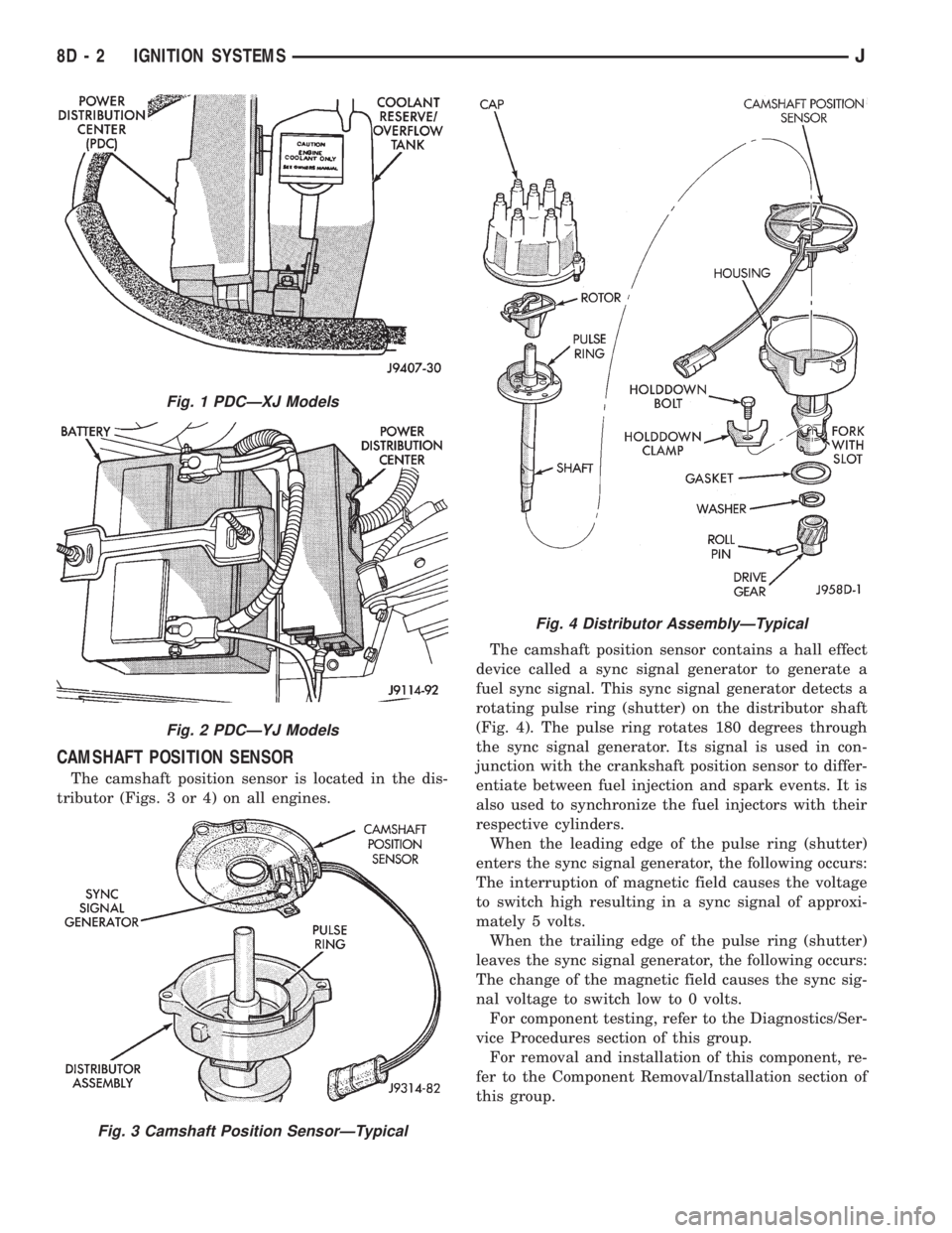
The camshaft position sensor is located in the dis-
tributor (Figs. 3 or 4) on all engines.The camshaft position sensor contains a hall effect
device called a sync signal generator to generate a
fuel sync signal. This sync signal generator detects a
rotating pulse ring (shutter) on the distributor shaft
(Fig. 4). The pulse ring rotates 180 degrees through
the sync signal generator. Its signal is used in con-
junction with the crankshaft position sensor to differ-
entiate between fuel injection and spark events. It is
also used to synchronize the fuel injectors with their
respective cylinders.
When the leading edge of the pulse ring (shutter)
enters the sync signal generator, the following occurs:
The interruption of magnetic field causes the voltage
to switch high resulting in a sync signal of approxi-
mately 5 volts.
When the trailing edge of the pulse ring (shutter)
leaves the sync signal generator, the following occurs:
The change of the magnetic field causes the sync sig-
nal voltage to switch low to 0 volts.
For component testing, refer to the Diagnostics/Ser-
vice Procedures section of this group.
For removal and installation of this component, re-
fer to the Component Removal/Installation section of
this group.
Fig. 1 PDCÐXJ Models
Fig. 2 PDCÐYJ Models
Fig. 3 Camshaft Position SensorÐTypical
Fig. 4 Distributor AssemblyÐTypical
8D - 2 IGNITION SYSTEMSJ
Page 315 of 2198
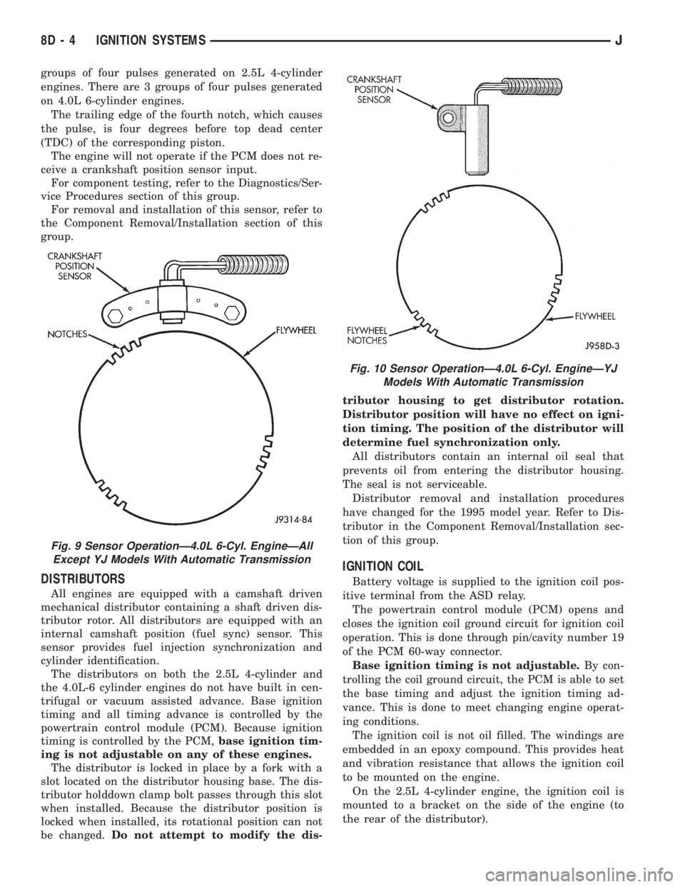
groups of four pulses generated on 2.5L 4-cylinder
engines. There are 3 groups of four pulses generated
on 4.0L 6-cylinder engines.
The trailing edge of the fourth notch, which causes
the pulse, is four degrees before top dead center
(TDC) of the corresponding piston.
The engine will not operate if the PCM does not re-
ceive a crankshaft position sensor input.
For component testing, refer to the Diagnostics/Ser-
vice Procedures section of this group.
For removal and installation of this sensor, refer to
the Component Removal/Installation section of this
group.
DISTRIBUTORS
All engines are equipped with a camshaft driven
mechanical distributor containing a shaft driven dis-
tributor rotor. All distributors are equipped with an
internal camshaft position (fuel sync) sensor. This
sensor provides fuel injection synchronization and
cylinder identification.
The distributors on both the 2.5L 4-cylinder and
the 4.0L-6 cylinder engines do not have built in cen-
trifugal or vacuum assisted advance. Base ignition
timing and all timing advance is controlled by the
powertrain control module (PCM). Because ignition
timing is controlled by the PCM,base ignition tim-
ing is not adjustable on any of these engines.
The distributor is locked in place by a fork with a
slot located on the distributor housing base. The dis-
tributor holddown clamp bolt passes through this slot
when installed. Because the distributor position is
locked when installed, its rotational position can not
be changed.Do not attempt to modify the dis-tributor housing to get distributor rotation.
Distributor position will have no effect on igni-
tion timing. The position of the distributor will
determine fuel synchronization only.
All distributors contain an internal oil seal that
prevents oil from entering the distributor housing.
The seal is not serviceable.
Distributor removal and installation procedures
have changed for the 1995 model year. Refer to Dis-
tributor in the Component Removal/Installation sec-
tion of this group.
IGNITION COIL
Battery voltage is supplied to the ignition coil pos-
itive terminal from the ASD relay.
The powertrain control module (PCM) opens and
closes the ignition coil ground circuit for ignition coil
operation. This is done through pin/cavity number 19
of the PCM 60-way connector.
Base ignition timing is not adjustable.By con-
trolling the coil ground circuit, the PCM is able to set
the base timing and adjust the ignition timing ad-
vance. This is done to meet changing engine operat-
ing conditions.
The ignition coil is not oil filled. The windings are
embedded in an epoxy compound. This provides heat
and vibration resistance that allows the ignition coil
to be mounted on the engine.
On the 2.5L 4-cylinder engine, the ignition coil is
mounted to a bracket on the side of the engine (to
the rear of the distributor).
Fig. 9 Sensor OperationÐ4.0L 6-Cyl. EngineÐAll
Except YJ Models With Automatic Transmission
Fig. 10 Sensor OperationÐ4.0L 6-Cyl. EngineÐYJ
Models With Automatic Transmission
8D - 4 IGNITION SYSTEMSJ
Page 316 of 2198
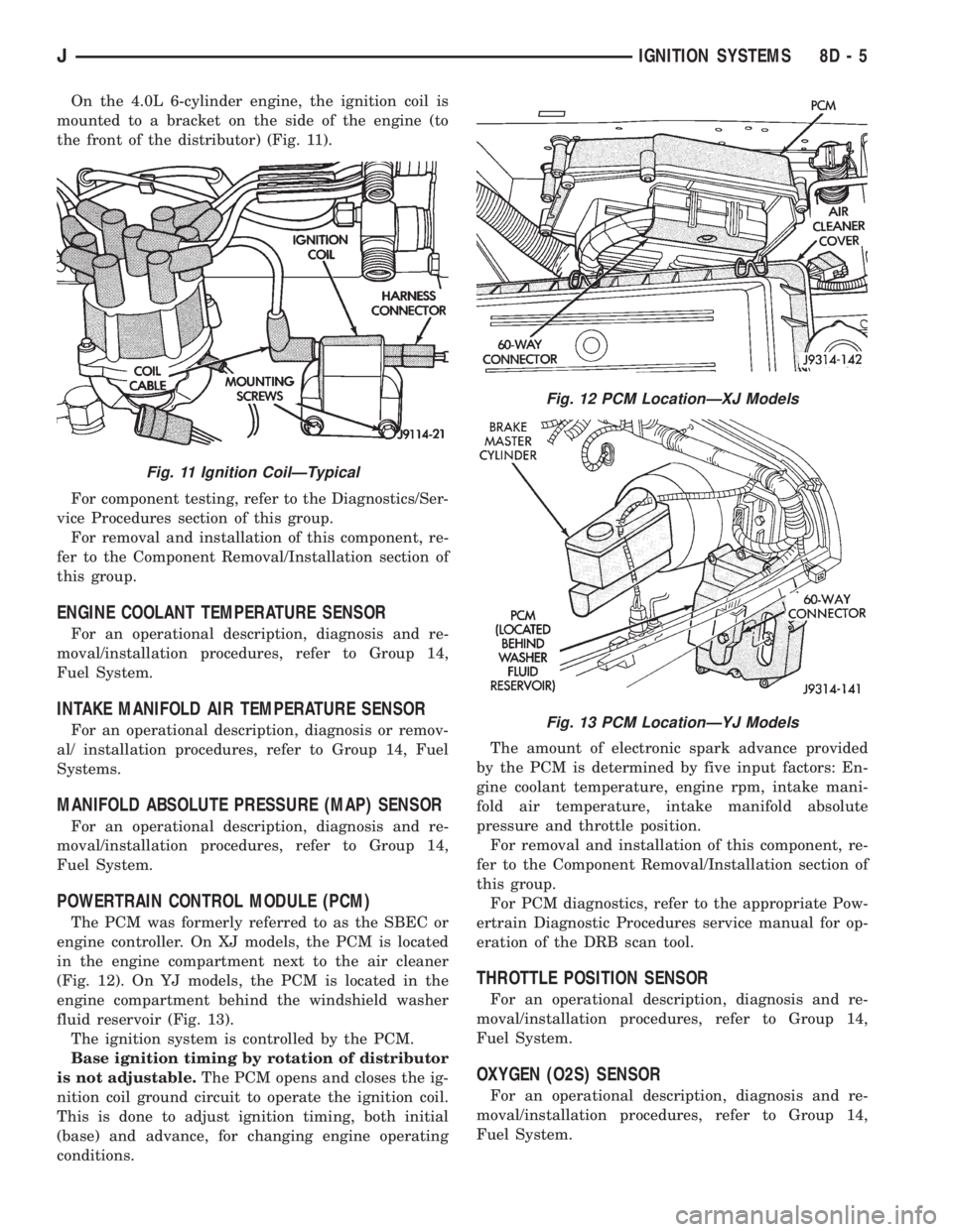
On the 4.0L 6-cylinder engine, the ignition coil is
mounted to a bracket on the side of the engine (to
the front of the distributor) (Fig. 11).
For component testing, refer to the Diagnostics/Ser-
vice Procedures section of this group.
For removal and installation of this component, re-
fer to the Component Removal/Installation section of
this group.
ENGINE COOLANT TEMPERATURE SENSOR
For an operational description, diagnosis and re-
moval/installation procedures, refer to Group 14,
Fuel System.
INTAKE MANIFOLD AIR TEMPERATURE SENSOR
For an operational description, diagnosis or remov-
al/ installation procedures, refer to Group 14, Fuel
Systems.
MANIFOLD ABSOLUTE PRESSURE (MAP) SENSOR
For an operational description, diagnosis and re-
moval/installation procedures, refer to Group 14,
Fuel System.
POWERTRAIN CONTROL MODULE (PCM)
The PCM was formerly referred to as the SBEC or
engine controller. On XJ models, the PCM is located
in the engine compartment next to the air cleaner
(Fig. 12). On YJ models, the PCM is located in the
engine compartment behind the windshield washer
fluid reservoir (Fig. 13).
The ignition system is controlled by the PCM.
Base ignition timing by rotation of distributor
is not adjustable.The PCM opens and closes the ig-
nition coil ground circuit to operate the ignition coil.
This is done to adjust ignition timing, both initial
(base) and advance, for changing engine operating
conditions.The amount of electronic spark advance provided
by the PCM is determined by five input factors: En-
gine coolant temperature, engine rpm, intake mani-
fold air temperature, intake manifold absolute
pressure and throttle position.
For removal and installation of this component, re-
fer to the Component Removal/Installation section of
this group.
For PCM diagnostics, refer to the appropriate Pow-
ertrain Diagnostic Procedures service manual for op-
eration of the DRB scan tool.
THROTTLE POSITION SENSOR
For an operational description, diagnosis and re-
moval/installation procedures, refer to Group 14,
Fuel System.
OXYGEN (O2S) SENSOR
For an operational description, diagnosis and re-
moval/installation procedures, refer to Group 14,
Fuel System.
Fig. 11 Ignition CoilÐTypical
Fig. 12 PCM LocationÐXJ Models
Fig. 13 PCM LocationÐYJ Models
JIGNITION SYSTEMS 8D - 5
Page 317 of 2198

DIAGNOSTICS/SERVICE PROCEDURES
INDEX
page page
Automatic Shutdown (ASD) Relay Test.......... 6
Camshaft Position Sensor Test................ 6
Crankshaft Position Sensor Test............... 7
Distributor Cap............................ 7
Distributor Rotor........................... 8
DRB Scan Tool............................ 8
Engine Coolant Temperature Sensor Test........ 9
General Information........................ 6
Ignition Coil.............................. 9
Ignition Secondary Circuit Diagnosis........... 10Ignition Timing............................ 11
Intake Manifold Air Temperature Sensor Test..... 11
Manifold Absolute Pressure (MAP) Sensor Test . . . 11
On-Board Diagnostics...................... 15
Oxygen (O2S) Sensor Tests................. 15
Powertrain Control Module (PCM)............. 11
Spark Plug Secondary Cables................ 14
Spark Plugs............................. 12
Throttle Position Sensor Test................. 15
GENERAL INFORMATION
This section of the group, Diagnostics/Service Pro-
cedures, will discuss basic ignition system diagnostics
and service adjustments.
For system operation and component identification,
refer to the Component Identification/System Opera-
tion section of this group.
For removal or installation of ignition system com-
ponents, refer to the Component Removal/Installa-
tion section of this group.
For other useful information, refer to the On-Board
Diagnostics section.
For operation of the DRB Scan Tool, refer to the
appropriate Powertrain Diagnostic Procedures ser-
vice manual.
AUTOMATIC SHUTDOWN (ASD) RELAY TEST
To perform a complete test of this relay and its cir-
cuitry, refer to the DRB scan tool. Also refer to the
appropriate Powertrain Diagnostics Procedures man-
ual. To test the relay only, refer to RelaysÐOpera-
tion/Testing in the Group 14, Fuel Systems section.
CAMSHAFT POSITION SENSOR TEST
To perform a complete test of this sensor and its
circuitry, refer to the DRB scan tool. Also refer to the
appropriate Powertrain Diagnostics Procedures man-
ual. To test the sensor only, refer to the following:
The camshaft position sensor is located in the dis-
tributor (Fig. 1).
To perform a complete test of this sensor and its
circuitry, refer to the DRB scan tool. Also refer to the
appropriate Powertrain Diagnostics Procedures man-
ual. To test the sensor only, refer to the following:
For this test, an analog (non-digital) voltme-
ter is needed.Do not remove the distributor connec-
tor from the distributor. Using small paper clips,
insert them into the backside of the distributor wire
harness connector to make contact with the termi-nals. Be sure that the connector is not damaged
when inserting the paper clips. Attach voltmeter
leads to these paper clips.
(1) Connect the positive (+) voltmeter lead into the
sensor output wire. This is at done the distributor
wire harness connector. For wire identification, refer
to Group 8W, Wiring Diagrams.
(2) Connect the negative (-) voltmeter lead into the
ground wire. For wire identification, refer to Group
8W, Wiring Diagrams.
(3) Set the voltmeter to the 15 Volt DC scale.
(4) Remove distributor cap from distributor (two
screws). Rotate (crank) the engine until the distribu-
tor rotor is pointed to approximately the 11 o'clock
position. The movable pulse ring should now be
within the sensor pickup.
(5) Turn ignition key to ON position. The voltmeter
should read approximately 5.0 volts.
(6) If voltage is not present, check the voltmeter
leads for a good connection.
(7) If voltage is still not present, check for voltage
at the supply wire. For wire identification, refer to
Group 8W, Wiring Diagrams.
Fig. 1 Camshaft Position SensorÐTypical
8D - 6 IGNITION SYSTEMSJ
Page 320 of 2198
IGNITION COIL
To perform a complete test of the ignition coil and
its circuitry, refer to the DRB scan tool. Also refer tothe appropriate Powertrain Diagnostics Procedures
manual. To test the coil only, refer to the following:
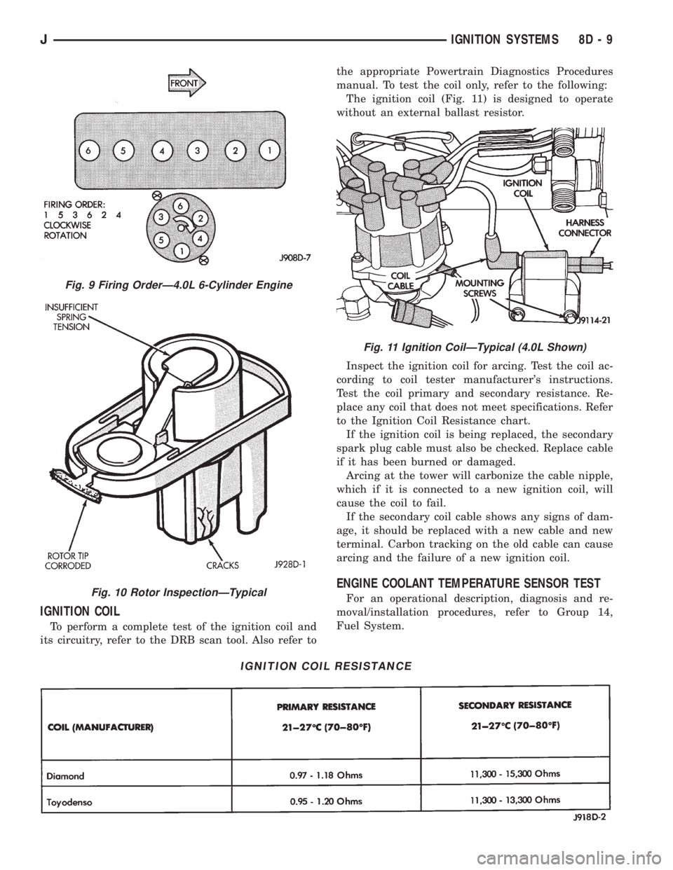
The ignition coil (Fig. 11) is designed to operate
without an external ballast resistor.
Inspect the ignition coil for arcing. Test the coil ac-
cording to coil tester manufacturer's instructions.
Test the coil primary and secondary resistance. Re-
place any coil that does not meet specifications. Refer
to the Ignition Coil Resistance chart.
If the ignition coil is being replaced, the secondary
spark plug cable must also be checked. Replace cable
if it has been burned or damaged.
Arcing at the tower will carbonize the cable nipple,
which if it is connected to a new ignition coil, will
cause the coil to fail.
If the secondary coil cable shows any signs of dam-
age, it should be replaced with a new cable and new
terminal. Carbon tracking on the old cable can cause
arcing and the failure of a new ignition coil.
ENGINE COOLANT TEMPERATURE SENSOR TEST
For an operational description, diagnosis and re-
moval/installation procedures, refer to Group 14,
Fuel System.
IGNITION COIL RESISTANCE
Fig. 9 Firing OrderÐ4.0L 6-Cylinder Engine
Fig. 10 Rotor InspectionÐTypical
Fig. 11 Ignition CoilÐTypical (4.0L Shown)
JIGNITION SYSTEMS 8D - 9