1995 JEEP CHEROKEE floor pan
[x] Cancel search: floor panPage 1152 of 2198
(29) Disconnect the exhaust pipe from the mani-
fold.
(30) Disconnect the engine speed sensor wire con-
nection.
(31) Remove the exhaust pipe support.
(32) Remove the flywheel and converter housing
access cover.
(33)Vehicles with Automatic Transmission:
(a) Mark the converter and drive plate location.
(b) Remove the converter-to-drive plate bolts.
(34) Remove the upper flywheel and converter
housing bolts and loosen the bottom bolts.
(35) Remove the engine mount cushion-to-engine
compartment bracket bolts.
(36) Lower the vehicle.
(37) Attach a lifting device to the engine.
(38) Raise the engine off the front supports.
(39) Place a support or floor jack under the con-
verter (or flywheel) housing.
(40) Remove the remaining converter (or flywheel)
housing bolts.
(41) Lift the engine out of the engine compart-
ment.
INSTALLATION
CAUTION: When installing the engine into a vehicle
equipped with an automatic transmission, be care-
ful not to damage the trigger wheel on the flywheel.
(1) Attach a lifting device to the engine and lower
the engine into the engine compartment. For easier
installation, it may be necessary to remove the en-
gine mount cushions from the engine mount bracket
as an aide in alignment of the engine to the trans-
mission.
(2)Vehicles with Manual Transmission:
(a) Insert the transmission shaft into the clutch
spline.
(b) Align the flywheel housing with the engine.(c) Install and tighten the flywheel housing lower
bolts finger tight.
(3)Vehicles with Automatic Transmission:
(a) Align the transmission torque converter hous-
ing with the engine.
(b) Loosely install the converter housing lower
bolts and install the next higher bolt and nut on
each side.
(c) Tighten all 4 bolts finger tight.
(4) Install the engine mount cushions (if removed).
(5) Lower the engine and engine mount cushions
onto the engine compartment brackets. Install the
bolts and finger tighten the nuts.
(6) Remove the engine lifting device.
(7) Raise and support the vehicle.
(8) Install the remaining flywheel and converter
housing bolts. Tighten all bolts to 38 Nzm (28 ft. lbs.)
torque.
(9)Vehicles with Automatic Transmission:
(a) Install the converter-to-drive plate bolts.
(b) Ensure the installation reference marks are
aligned.
(10) Install the flywheel and converter housing ac-
cess cover.
(11) Install the exhaust pipe support and tighten
the screw.
(12) Tighten the engine mount-to-bracket bolts.
(13) Connect the engine speed sensor wire connec-
tions and tighten the screws.
(14) Connect the exhaust pipe to the manifold.
(15) Install the starter motor and connect the ca-
ble.
(16) Connect the wires to the starter motor sole-
noid.
(17) Lower the vehicle.
(18) Connect all the vacuum hoses and wire con-
nectors identified during engine removal.
(19) If equipped with power steering:
(a) Remove the protective caps
(b) Connect the hoses to the fittings at the steer-
ing gear. Tighten the nut to 52 Nzm (38 ft. lbs.)
torque.
(c) Fill the pump reservoir with fluid.
(20) Install the power brake vacuum check valve to
the booster, if equipped.
(21) Connect the fuel inlet and return hoses at the
fuel rail. Verify that the quick-connect fitting assem-
bly fits securely over the fuel lines by giving the fuel
lines a firm tug.
(22) Install the fuel line bracket to the intake man-
ifold.
(23) Connect the distributor electrical connector
and oil pressure switch connector.
(24) Connect the injection system wire harness
connector on the dash panel.
(25) Connect the line pressure cable (if equipped
with automatic transmission).
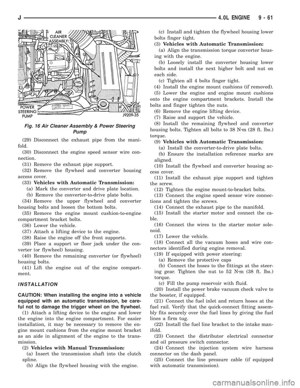
Fig. 16 Air Cleaner Assembly & Power Steering
Pump
J4.0L ENGINE 9 - 61
Page 1172 of 2198
OIL PUMP
A gear-type oil pump is mounted at the underside
of the cylinder block opposite the No.4 main bearing.
The pump incorporates a nonadjustable pressure
relief valve to limit maximum pressure to 517 kPa
(75 psi). In the relief position, the valve permits oil to
bypass through a passage in the pump body to the
inlet side of the pump.
Oil pump removal or replacement will not affect
the distributor timing because the distributor drive
gear remains in mesh with the camshaft gear.
REMOVAL
(1) Drain the engine oil.
(2) Remove the oil pan.
(3) Remove the pump-to-cylinder block attaching
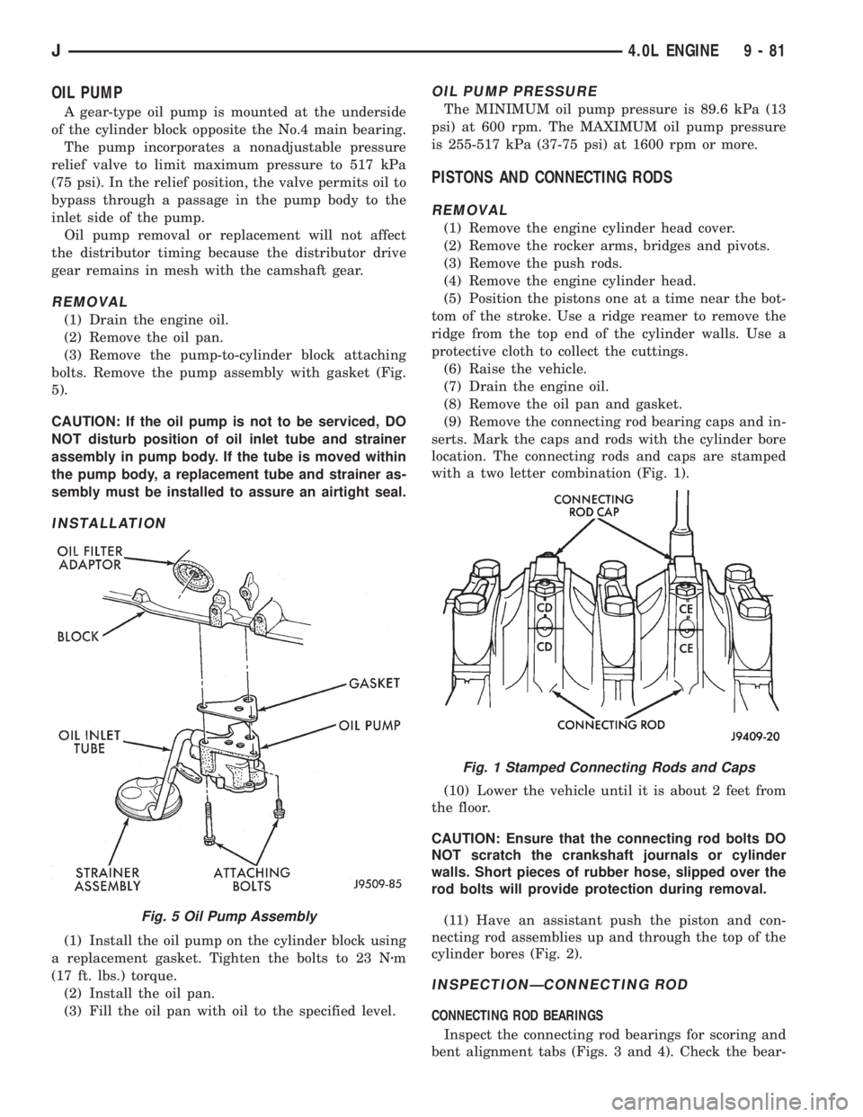
bolts. Remove the pump assembly with gasket (Fig.
5).
CAUTION: If the oil pump is not to be serviced, DO
NOT disturb position of oil inlet tube and strainer
assembly in pump body. If the tube is moved within
the pump body, a replacement tube and strainer as-
sembly must be installed to assure an airtight seal.
INSTALLATION
(1) Install the oil pump on the cylinder block using
a replacement gasket. Tighten the bolts to 23 Nzm
(17 ft. lbs.) torque.
(2) Install the oil pan.
(3) Fill the oil pan with oil to the specified level.
OIL PUMP PRESSURE
The MINIMUM oil pump pressure is 89.6 kPa (13
psi) at 600 rpm. The MAXIMUM oil pump pressure
is 255-517 kPa (37-75 psi) at 1600 rpm or more.
PISTONS AND CONNECTING RODS
REMOVAL
(1) Remove the engine cylinder head cover.
(2) Remove the rocker arms, bridges and pivots.
(3) Remove the push rods.
(4) Remove the engine cylinder head.
(5) Position the pistons one at a time near the bot-
tom of the stroke. Use a ridge reamer to remove the
ridge from the top end of the cylinder walls. Use a
protective cloth to collect the cuttings.
(6) Raise the vehicle.
(7) Drain the engine oil.
(8) Remove the oil pan and gasket.
(9) Remove the connecting rod bearing caps and in-
serts. Mark the caps and rods with the cylinder bore
location. The connecting rods and caps are stamped
with a two letter combination (Fig. 1).
(10) Lower the vehicle until it is about 2 feet from
the floor.
CAUTION: Ensure that the connecting rod bolts DO
NOT scratch the crankshaft journals or cylinder
walls. Short pieces of rubber hose, slipped over the
rod bolts will provide protection during removal.
(11) Have an assistant push the piston and con-
necting rod assemblies up and through the top of the
cylinder bores (Fig. 2).
INSPECTIONÐCONNECTING ROD
CONNECTING ROD BEARINGS
Inspect the connecting rod bearings for scoring and
bent alignment tabs (Figs. 3 and 4). Check the bear-
Fig. 5 Oil Pump Assembly
Fig. 1 Stamped Connecting Rods and Caps
J4.0L ENGINE 9 - 81
Page 1188 of 2198
EXHAUST SYSTEM AND INTAKE MANIFOLD
CONTENTS
page page
EXHAUST SYSTEM....................... 1
EXHAUST SYSTEM DIAGNOSIS............. 2SERVICE PROCEDURES................... 3
TORQUE SPECIFICATIONS................ 10
EXHAUST SYSTEM
GENERAL INFORMATION
The basic exhaust system consists of an engine ex-
haust manifold, exhaust pipe with oxygen sensor, cat-
alytic converter, exhaust heat shield(s), muffler and
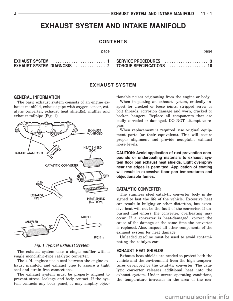
exhaust tailpipe (Fig. 1).
The exhaust system uses a single muffler with a
single monolithic-type catalytic converter.
The 4.0L engines use a seal between the engine ex-
haust manifold and exhaust pipe to assure a tight
seal and strain free connections.
The exhaust system must be properly aligned to
prevent stress, leakage and body contact. If the sys-
tem contacts any body panel, it may amplify objec-tionable noises originating from the engine or body.
When inspecting an exhaust system, critically in-
spect for cracked or loose joints, stripped screw or
bolt threads, corrosion damage and worn, cracked or
broken hangers. Replace all components that are
badly corroded or damaged. DO NOT attempt to re-
pair.
When replacement is required, use original equip-
ment parts (or their equivalent). This will assure
proper alignment and provide acceptable exhaust
noise levels.
CAUTION: Avoid application of rust prevention com-
pounds or undercoating materials to exhaust sys-
tem floor pan exhaust heat shields. Light overspray
near the edges is permitted. Application of coating
will result in excessive floor pan temperatures and
objectionable fumes.
CATALYTIC CONVERTER
The stainless steel catalytic converter body is de-
signed to last the life of the vehicle. Excessive heat
can result in bulging or other distortion, but exces-
sive heat will not be the fault of the converter. If un-
burned fuel enters the converter, overheating may
occur. If a converter is heat-damaged, correct the
cause of the damage at the same time the converter
is replaced. Also, inspect all other components of the
exhaust system for heat damage.
Unleaded gasoline must be used to avoid contami-
nating the catalyst core.
EXHAUST HEAT SHIELDS
Exhaust heat shields are needed to protect both the
vehicle and the environment from the high tempera-
tures developed by the catalytic converter. The cata-
lytic converter releases additional heat into the
exhaust system. Under severe operating conditions,
the temperature increases in the area of the con-
Fig. 1 Typical Exhaust System
JEXHAUST SYSTEM AND INTAKE MANIFOLD 11 - 1
Page 1189 of 2198
verter. Such conditions can exist when the engine
misfires or otherwise does not operate at peak effi-
ciency.
DO NOT remove spark plug wires from plugs or by
any other means short out cylinders. Failure of the
catalytic converter can occur due to a temperature
increase caused by unburned fuel passing through
the converter.DO NOT allow the engine to operate at fast idle for
extended periods (over 5 minutes). This condition
may result in excessive temperatures in the exhaust
system and on the floor pan.
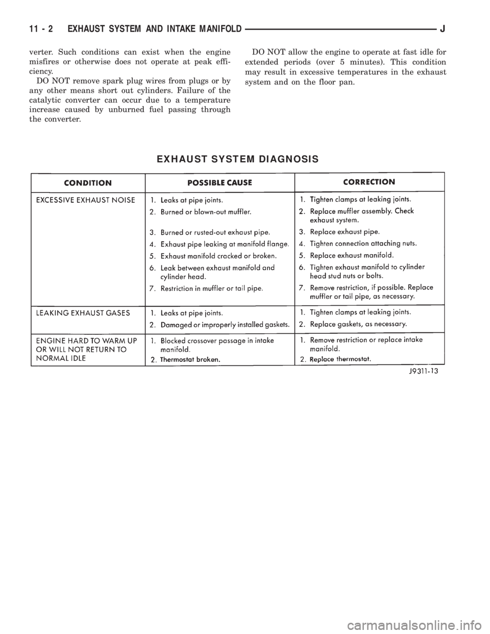
EXHAUST SYSTEM DIAGNOSIS
11 - 2 EXHAUST SYSTEM AND INTAKE MANIFOLDJ
Page 1193 of 2198
²To remove an original equipment exhaust tailpipe/
muffler combination, cut the exhaust tailpipe close to
the muffler. Collapse the part remaining in the muf-
fler and remove.
²To remove a service exhaust tailpipe/muffler com-
bination, apply heat until the metal becomes cherry
red. Remove the exhaust tailpipe/muffler clamp and
twist the exhaust tailpipe out of the muffler.
INSTALLATION
(1) Install the muffler onto the catalytic converter.
Install the clamp and tighten the nuts finger tight.
(2) Install the exhaust tailpipe into the rear of the
muffler.
(3) Install the exhaust tailpipe/muffler assembly on
the rear exhaust tailpipe hanger. Make sure that the
exhaust tailpipe has sufficient clearance from the
floor pan.
(4) Install the remaining clamps and the front ex-
haust tailpipe hanger.
(5) Tighten the nuts on the muffler-to-catalytic
converter clamp to 61 Nzm (45 ft. lbs.) torque (Fig. 6).
Tighten the nuts on the rear exhaust tailpipe clamp
to 14 Nzm (10 ft. lbs.) torque (Fig. 7).
(6) Lower the vehicle.
(7) Start the engine and inspect for exhaust leaks
and exhaust system contact with the body panels.
Adjust the alignment, if needed.
MUFFLER AND EXHAUST TAILPIPEÐYJ VEHICLES
All original equipment exhaust systems are manu-
factured with the exhaust tailpipe welded to the muf-
fler. Service replacement mufflers and exhaust
tailpipes are clamped together.
WARNING: IF TORCHES ARE USED WHEN WORK-
ING ON THE EXHAUST SYSTEM, DO NOT ALLOW
THE FLAME NEAR THE FUEL LINES.
REMOVAL
(1) Raise the vehicle and support the rear of the
vehicle by the side rails and allow the axle to hang
free.
(2) Remove the front muffler clamp from the cata-
lytic converter and muffler connection (Fig. 6).
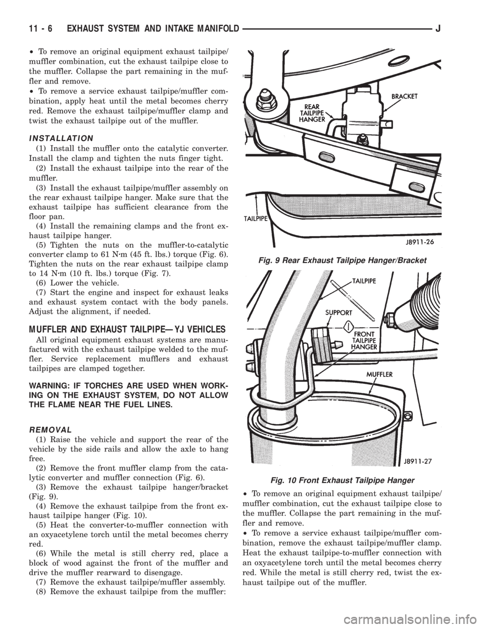
(3) Remove the exhaust tailpipe hanger/bracket
(Fig. 9).
(4) Remove the exhaust tailpipe from the front ex-
haust tailpipe hanger (Fig. 10).
(5) Heat the converter-to-muffler connection with
an oxyacetylene torch until the metal becomes cherry
red.
(6) While the metal is still cherry red, place a
block of wood against the front of the muffler and
drive the muffler rearward to disengage.
(7) Remove the exhaust tailpipe/muffler assembly.
(8) Remove the exhaust tailpipe from the muffler:²To remove an original equipment exhaust tailpipe/
muffler combination, cut the exhaust tailpipe close to
the muffler. Collapse the part remaining in the muf-
fler and remove.
²To remove a service exhaust tailpipe/muffler com-
bination, remove the exhaust tailpipe/muffler clamp.
Heat the exhaust tailpipe-to-muffler connection with
an oxyacetylene torch until the metal becomes cherry
red. While the metal is still cherry red, twist the ex-
haust tailpipe out of the muffler.
Fig. 9 Rear Exhaust Tailpipe Hanger/Bracket
Fig. 10 Front Exhaust Tailpipe Hanger
11 - 6 EXHAUST SYSTEM AND INTAKE MANIFOLDJ
Page 1194 of 2198
INSTALLATION
(1) Install the muffler onto the catalytic converter
outlet. Ensure that the locator on the converter
aligns with the notch on the muffler, if so equipped.
Install the clamp and tighten the nuts finger tight.
(2) Install the exhaust tailpipe into the muffler
outlet. Ensure that the locator on the exhaust
tailpipe aligns with the notch on the muffler, if so
equipped. Install the clamp and tighten the nuts fin-
ger tight.
(3) Install the front exhaust tailpipe supports and
the rear exhaust tailpipe hanger. Ensure that the ex-
haust tailpipe has sufficient clearance from the floor
pan and shields.
(4) Tighten the nuts on the muffler-to-catalytic
converter and the muffler-to-exhaust tailpipe clamps
to 61 Nzm (45 ft. lbs.) torque.
(5) Lower the vehicle.
(6) Start the engine and inspect for exhaust leaks
and contact with the body panels and shields.
ENGINE EXHAUST MANIFOLDÐ2.5L ENGINE
REMOVAL
(1) Disconnect the battery negative cable.
(2) Remove all components attached to the intake
manifold.
(3) Raise the vehicle.
(4) Disconnect the exhaust pipe from the engine
exhaust manifold.
(5) Lower the vehicle.
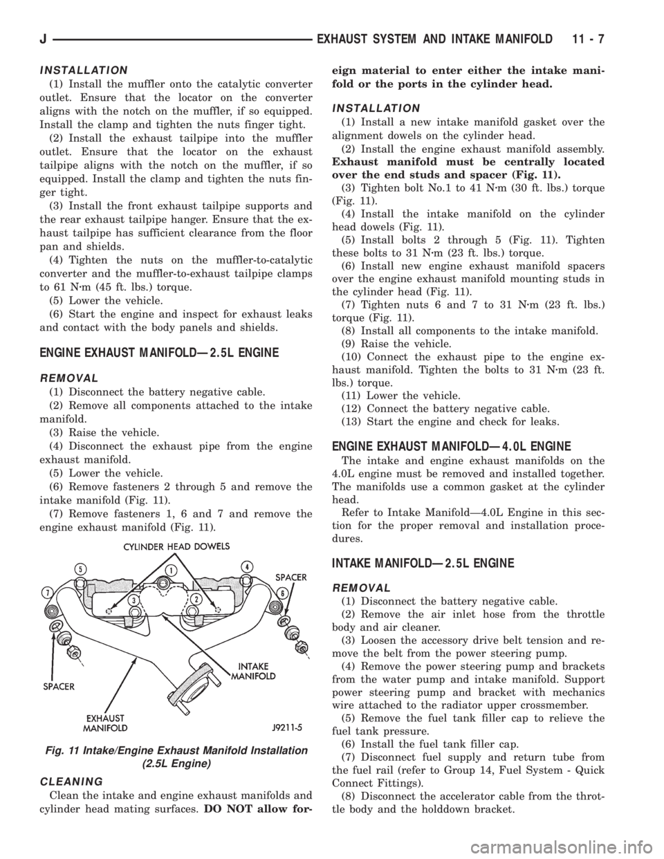
(6) Remove fasteners 2 through 5 and remove the
intake manifold (Fig. 11).
(7) Remove fasteners 1, 6 and 7 and remove the
engine exhaust manifold (Fig. 11).
CLEANING
Clean the intake and engine exhaust manifolds and
cylinder head mating surfaces.DO NOT allow for-eign material to enter either the intake mani-
fold or the ports in the cylinder head.
INSTALLATION
(1) Install a new intake manifold gasket over the
alignment dowels on the cylinder head.
(2) Install the engine exhaust manifold assembly.
Exhaust manifold must be centrally located
over the end studs and spacer (Fig. 11).
(3) Tighten bolt No.1 to 41 Nzm (30 ft. lbs.) torque
(Fig. 11).
(4) Install the intake manifold on the cylinder
head dowels (Fig. 11).
(5) Install bolts 2 through 5 (Fig. 11). Tighten
these bolts to 31 Nzm (23 ft. lbs.) torque.
(6) Install new engine exhaust manifold spacers
over the engine exhaust manifold mounting studs in
the cylinder head (Fig. 11).
(7) Tighten nuts 6 and 7 to 31 Nzm (23 ft. lbs.)
torque (Fig. 11).
(8) Install all components to the intake manifold.
(9) Raise the vehicle.
(10) Connect the exhaust pipe to the engine ex-
haust manifold. Tighten the bolts to 31 Nzm (23 ft.
lbs.) torque.
(11) Lower the vehicle.
(12) Connect the battery negative cable.
(13) Start the engine and check for leaks.
ENGINE EXHAUST MANIFOLDÐ4.0L ENGINE
The intake and engine exhaust manifolds on the
4.0L engine must be removed and installed together.
The manifolds use a common gasket at the cylinder
head.
Refer to Intake ManifoldÐ4.0L Engine in this sec-
tion for the proper removal and installation proce-
dures.
INTAKE MANIFOLDÐ2.5L ENGINE
REMOVAL
(1) Disconnect the battery negative cable.
(2) Remove the air inlet hose from the throttle
body and air cleaner.
(3) Loosen the accessory drive belt tension and re-
move the belt from the power steering pump.
(4) Remove the power steering pump and brackets
from the water pump and intake manifold. Support
power steering pump and bracket with mechanics
wire attached to the radiator upper crossmember.
(5) Remove the fuel tank filler cap to relieve the
fuel tank pressure.
(6) Install the fuel tank filler cap.
(7) Disconnect fuel supply and return tube from
the fuel rail (refer to Group 14, Fuel System - Quick
Connect Fittings).
(8) Disconnect the accelerator cable from the throt-
tle body and the holddown bracket.
Fig. 11 Intake/Engine Exhaust Manifold Installation
(2.5L Engine)
JEXHAUST SYSTEM AND INTAKE MANIFOLD 11 - 7
Page 1232 of 2198
ACCELERATOR PEDAL AND THROTTLE CABLE
GENERAL INFORMATION
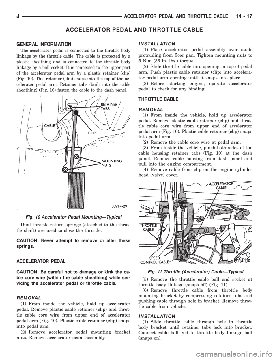
The accelerator pedal is connected to the throttle body
linkage by the throttle cable. The cable is protected by a
plastic sheathing and is connected to the throttle body
linkage by a ball socket. It is connected to the upper part
of the accelerator pedal arm by a plastic retainer (clip)
(Fig. 10). This retainer (clip) snaps into the top of the ac-
celerator pedal arm. Retainer tabs (built into the cable
sheathing) (Fig. 10) fasten the cable to the dash panel.
Dual throttle return springs (attached to the throt-
tle shaft) are used to close the throttle.
CAUTION: Never attempt to remove or alter these
springs.
ACCELERATOR PEDAL
CAUTION: Be careful not to damage or kink the ca-
ble core wire (within the cable sheathing) while ser-
vicing the accelerator pedal or throttle cable.
REMOVAL
(1) From inside the vehicle, hold up accelerator
pedal. Remove plastic cable retainer (clip) and throt-
tle cable core wire from upper end of accelerator
pedal arm (Fig. 10). Plastic cable retainer (clip) snaps
into pedal arm.
(2) Remove accelerator pedal mounting bracket
nuts. Remove accelerator pedal assembly.
INSTALLATION
(1) Place accelerator pedal assembly over studs
protruding from floor pan. Tighten mounting nuts to
5Nzm (36 in. lbs.) torque.
(2) Slide throttle cable into opening in top of pedal
arm. Push plastic cable retainer (clip) into accelera-
tor pedal arm opening until it snaps into place.
(3) Before starting engine, operate accelerator
pedal to check for any binding.
THROTTLE CABLE
REMOVAL
(1) From inside the vehicle, hold up accelerator
pedal. Remove plastic cable retainer (clip) and throt-
tle cable core wire from upper end of accelerator
pedal arm (Fig. 10). Plastic cable retainer (clip) snaps
into pedal arm.
(2) Remove the cable core wire at pedal arm.
(3) From inside the vehicle, pinch both sides of the
cable housing retainer tabs (Fig. 10) at the dash
panel. Remove cable housing from dash panel and
pull into the engine compartment.
(4) Remove cable from clip on the engine cylinder
head (valve) cover.
(5) Remove the throttle cable ball end socket at
throttle body linkage (snaps off) (Fig. 11).
(6) Remove throttle cable from throttle body
mounting bracket by compressing retainer tabs and
pushing cable through hole in bracket. Remove throt-
tle cable from vehicle.
INSTALLATION
(1) Slide throttle cable through hole in throttle
body bracket until retainer tabs lock into bracket.
Connect cable ball end to throttle body linkage ball
(snaps on).
Fig. 10 Accelerator Pedal MountingÐTypical
Fig. 11 Throttle (Accelerator) CableÐTypical
JACCELERATOR PEDAL AND THROTTLE CABLE 14 - 17
Page 1358 of 2198
(1) Make sure the front wheels are in thestraight
aheadposition.
(2) Disconnect the negative (ground) cable from the
battery.
(3) Remove steering wheel from column, refer to
Steering Wheel-Removal.
(4) Column shift vehicles, disconnect the shift ca-
ble grommet by prying it from the shift lever.
(5) Disconnect the column shaft to steering gear
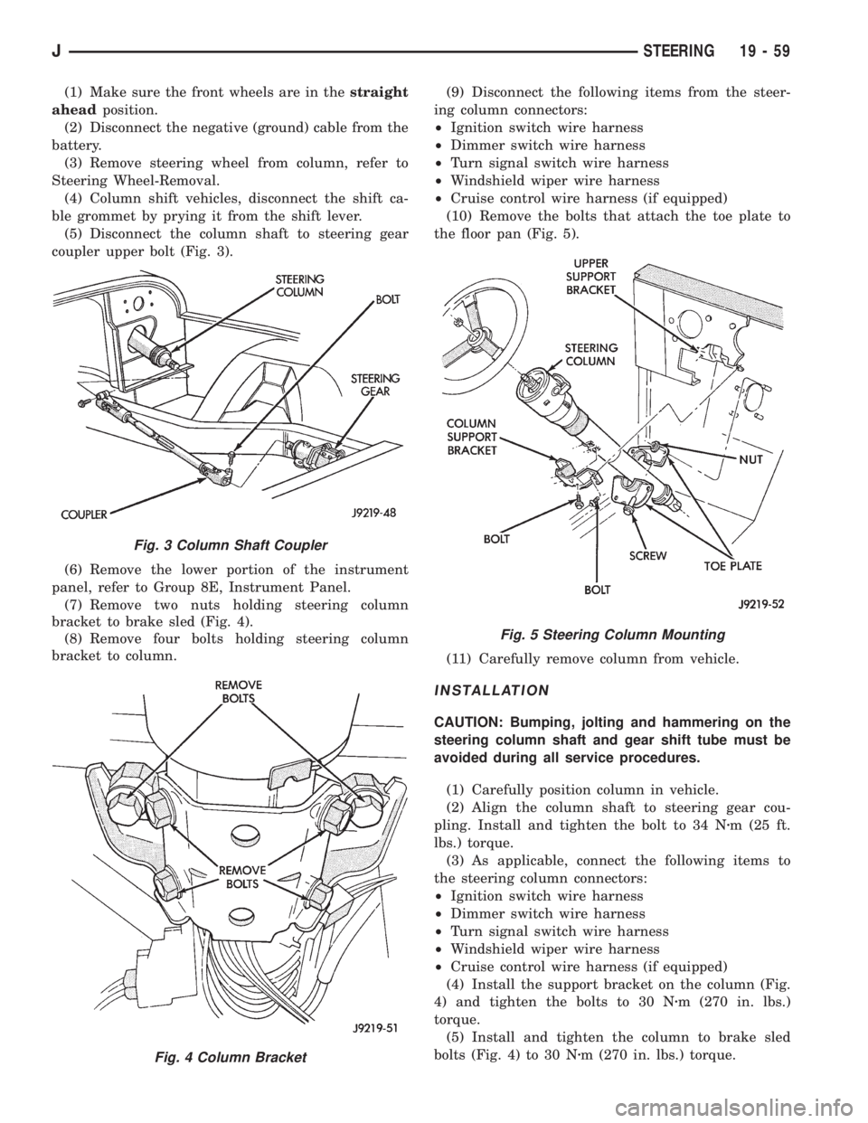
coupler upper bolt (Fig. 3).
(6) Remove the lower portion of the instrument
panel, refer to Group 8E, Instrument Panel.
(7) Remove two nuts holding steering column
bracket to brake sled (Fig. 4).
(8) Remove four bolts holding steering column
bracket to column.(9) Disconnect the following items from the steer-
ing column connectors:
²Ignition switch wire harness
²Dimmer switch wire harness
²Turn signal switch wire harness
²Windshield wiper wire harness
²Cruise control wire harness (if equipped)
(10) Remove the bolts that attach the toe plate to
the floor pan (Fig. 5).
(11) Carefully remove column from vehicle.
INSTALLATION
CAUTION: Bumping, jolting and hammering on the
steering column shaft and gear shift tube must be
avoided during all service procedures.
(1) Carefully position column in vehicle.
(2) Align the column shaft to steering gear cou-
pling. Install and tighten the bolt to 34 Nzm (25 ft.
lbs.) torque.
(3) As applicable, connect the following items to
the steering column connectors:
²Ignition switch wire harness
²Dimmer switch wire harness
²Turn signal switch wire harness
²Windshield wiper wire harness
²Cruise control wire harness (if equipped)
(4) Install the support bracket on the column (Fig.
4) and tighten the bolts to 30 Nzm (270 in. lbs.)
torque.
(5) Install and tighten the column to brake sled
bolts (Fig. 4) to 30 Nzm (270 in. lbs.) torque.
Fig. 3 Column Shaft Coupler
Fig. 4 Column Bracket
Fig. 5 Steering Column Mounting
JSTEERING 19 - 59