1995 JEEP CHEROKEE diagram
[x] Cancel search: diagramPage 422 of 2198
WIPER AND WASHER SYSTEMS
CONTENTS
page page
DIAGNOSIS - XJ......................... 3
DIAGNOSIS - YJ........................ 12
GENERAL INFORMATION - XJ.............. 1GENERAL INFORMATION - YJ............. 10
SERVICE PROCEDURES - XJ............... 6
SERVICE PROCEDURES - YJ.............. 17
GENERAL INFORMATION - XJ
Following are general descriptions of the major
components in the XJ (Cherokee) wiper and washer
systems. Refer to Group 8W - Wiring Diagrams for
complete circuit descriptions and diagrams.
WINDSHIELD WIPER SYSTEM
A two-speed wiper system is standard equipment
on all left-hand drive XJ models. An optional inter-
mittent wipe system is available. The intermittent
wipe system is standard equipment on all right-hand
drive XJ models. The two-speed wiper system allows
the driver to select from two wiper speeds. The inter-
mittent wipe system allows the driver to select from
two wiper speeds or an intermittent wipe feature
that allows a delay between wipes of 2 to 15 seconds.
Refer to the owner's manual for more information on
wiper system controls and operation.
The wipers will operate only when the ignition
switch is in the ACCESSORY or ON position. A cir-
cuit breaker near the fuseblock module protects the
circuitry of the wiper system on left-hand drive mod-
els. The circuit breaker is in the fuseblock module on
right-hand drive models.
WINDSHIELD WASHER SYSTEM
A electrically-operated windshield washer system is
standard equipment on all XJ models. The washers will
operate only when the ignition switch is in the ACCES-
SORY or ON position. A circuit breaker near the fuse-
block module protects the circuitry of the washer
system. Refer to the owner's manual for more informa-
tion on washer system controls and operation.
LIFTGATE WIPER/WASHER SYSTEM
A liftgate wiper/washer system is an available op-
tion on XJ models. The liftgate wiper is a fixed cycle
intermittent wipe system. A single switch on the in-
strument panel controls both the liftgate wiper and
washer functions. These systems will operate only
when the ignition switch is in the ON position. Fuse
1 in the fuseblock module protects the circuitry ofboth the liftgate wiper and washer. Refer to the own-
er's manual for more information on liftgate wiper/
washer system controls and operation.
WIPER ARMS, BLADES, AND ELEMENTS
All XJ models have two 18-inch windshield wiper
blades with replaceable rubber elements (squeegees).
Models with the liftgate wiper option use a single 12-
inch wiper blade with a replaceable rubber element
(squeegee).
Caution should be exercised to protect the rubber
squeegees from any petroleum-based cleaners or con-
taminants, which will rapidly deteriorate the squee-
gee rubber. If squeegees are damaged, worn or
contaminated they must be replaced.
Wiper squeegees exposed to the weather for a long
time tend to lose their wiping effectiveness. Periodic
cleaning of the squeegees is suggested to remove de-
posits of salt and road film. The wiper blades, arms
and windshield or liftgate glass should be cleaned
with a sponge or cloth and a mild detergent or non-
abrasive cleaner. If the squeegees continue to streak
or smear, they should be replaced.
The blades are mounted to spring-loaded wiper
arms. Spring tension of the wiper arms controls the
pressure applied to the blades on the glass. The
windshield wiper arms are attached by an integral
latch to the two wiper pivots on the cowl grille panel
at the base of the windshield. The liftgate wiper arm
is attached by an integral latch directly to the lift-
gate wiper motor output shaft on the liftgate panel.
The wiper arms and blades can not be adjusted or re-
paired. If faulty, they must be replaced.
WIPER LINKAGE AND PIVOTS
The wiper pivots are fastened to the cowl top panel
with screws beneath the cowl cover/grille panel. Each
pivot assembly can be replaced by removing the cowl
grille panel, unsnapping the linkage bushing(s) from
the pivot crank arm pins, and removing the mount-
ing screws.
JWIPER AND WASHER SYSTEMS 8K - 1
Page 425 of 2198
WINDSHIELD WASHER SYSTEM
WITH NON-INTERMITTENT WIPE
(1) Unplug washer pump connector. Measure resis-
tance between terminal B at pump and a clean chas-
sis ground. Meter should read zero ohms. If not OK,
repair open to ground.
(2) Turn ignition switch to ACCESSORY and
washer (multi-function) switch to ON.
(a) Measure voltage at washer pump connector
terminal A. Meter should read battery voltage. If
OK, replace washer pump. If not OK, go to next
step.
(b) Measure voltage at wiper/washer switch con-
nector terminal B. Meter should read battery volt-
age. If OK, repair open to washer pump. If not OK,
replace switch.
WITH INTERMITTENT WIPE
(1) Unplug washer pump connector. Measure resis-
tance between terminal B at pump and a clean chas-
sis ground. Meter should read zero ohms. If not OK,
repair open to ground.
(2) Turn ignition switch to ACCESSORY and
washer (multi-function) switch to ON.
(a) Measure voltage at intermittent wipe module
switch connector terminal B (pink wire). Meter
should read battery voltage. If not OK, replace
wiper switch.
(b) Measure voltage at wipe module motor con-
nector terminal B (brown wire). Meter should read
battery voltage. If not OK, replace module.
(c) Measure voltage at washer pump connector
terminal A at pump. Meter should read battery
voltage. If OK, replace pump. If not OK, repair
open from wipe module.
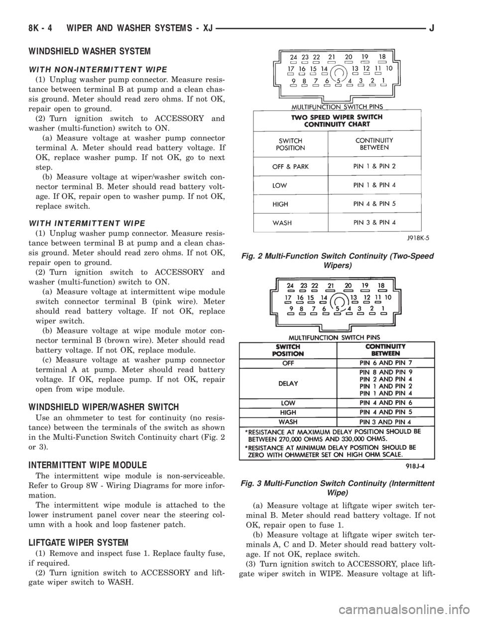
WINDSHIELD WIPER/WASHER SWITCH
Use an ohmmeter to test for continuity (no resis-
tance) between the terminals of the switch as shown
in the Multi-Function Switch Continuity chart (Fig. 2
or 3).
INTERMITTENT WIPE MODULE
The intermittent wipe module is non-serviceable.
Refer to Group 8W - Wiring Diagrams for more infor-
mation.
The intermittent wipe module is attached to the
lower instrument panel cover near the steering col-
umn with a hook and loop fastener patch.
LIFTGATE WIPER SYSTEM
(1) Remove and inspect fuse 1. Replace faulty fuse,
if required.
(2) Turn ignition switch to ACCESSORY and lift-
gate wiper switch to WASH.(a) Measure voltage at liftgate wiper switch ter-
minal B. Meter should read battery voltage. If not
OK, repair open to fuse 1.
(b) Measure voltage at liftgate wiper switch ter-
minals A, C and D. Meter should read battery volt-
age. If not OK, replace switch.
(3) Turn ignition switch to ACCESSORY, place lift-
gate wiper switch in WIPE. Measure voltage at lift-
Fig. 2 Multi-Function Switch Continuity (Two-Speed
Wipers)
Fig. 3 Multi-Function Switch Continuity (Intermittent
Wipe)
8K - 4 WIPER AND WASHER SYSTEMS - XJJ
Page 431 of 2198
GENERAL INFORMATION - YJ
Following are general descriptions of the major
components in the YJ (Wrangler) wiper and washer
systems. Refer to Group 8W - Wiring Diagrams for
complete circuit descriptions and diagrams.
WINDSHIELD WIPER SYSTEM
A two-speed wiper system is standard equipment
on all YJ models. An optional intermittent wipe sys-
tem is available. The standard system allows the
driver to select from two wiper speeds. The optional
intermittent wipe system allows the driver to select
from two wiper speeds or an intermittent wipe fea-
ture that allows a delay between wipes of 2 to 15 sec-
onds. Refer to the owner's manual for more
information on wiper system controls and operation.
The wipers will operate only when the ignition
switch is in the ACCESSORY or ON position. A cir-
cuit breaker in the fuseblock module protects the cir-
cuitry of the wiper system.
WINDSHIELD WASHER SYSTEM
A electrically-operated windshield washer system is
standard equipment on all YJ models. The washers
will operate only when the ignition switch is in the
ACCESSORY or ON position. A circuit breaker in the
fuseblock module protects the circuitry of the washer
system. Refer to the owner's manual for more infor-
mation on washer system controls and operation.
LIFTGATE WIPER/WASHER SYSTEM
A liftgate wiper/washer system is an available op-
tion on YJ models equipped with the optional hard-
top. The liftgate wiper is a fixed cycle wipe system. A
single switch on the instrument panel controls both
the liftgate wiper and washer functions. These sys-
tems will operate only when the ignition switch is in
the ON position. Fuse 1 in the fuseblock module pro-
tects the circuitry of both the liftgate wiper and
washer. Refer to the owner's manual for more infor-
mation on liftgate wiper/washer system controls and
operation.
WIPER ARMS, BLADES, AND ELEMENTS
All YJ models have two 12-inch windshield wiper
blades with replaceable rubber elements (squeegees).
Models with the liftgate wiper option use a single 16-
inch wiper blade with a replaceable rubber element
(squeegee).
Caution should be exercised to protect the rubber
squeegees from any petroleum-based cleaners or con-
taminants, which will rapidly deteriorate the squee-
gee rubber. If squeegees are damaged, worn or
contaminated they must be replaced.
Wiper squeegees exposed to the weather for a long
time tend to lose their wiping effectiveness. Periodiccleaning of the squeegees is suggested to remove de-
posits of salt and road film. The wiper blades, arms
and windshield or liftgate glass should be cleaned
with a sponge or cloth and a mild detergent or non-
abrasive cleaner. If the squeegees continue to streak
or smear, they should be replaced.
The blades are mounted to spring-loaded wiper
arms. Spring tension of the wiper arms controls the
pressure applied to the blades on the glass. The
windshield wiper arms are attached by an integral
latch to the two wiper pivots on the windshield frame
at the base of the windshield. The liftgate wiper arm
is attached by an integral latch directly to the lift-
gate wiper motor output shaft on the liftgate glass.
The wiper arms and blades can not be adjusted or re-
paired. If faulty, they must be replaced.
WIPER LINKAGE AND PIVOTS
The wiper pivots are fastened to the windshield
frame with nuts. The pivots and linkage are serviced
through access holes in the interior side of the lower
windshield frame. The two pivots and their connect-
ing link are serviced as a unit. The drive link, which
connects the motor crank arm to the left pivot, is ser-
viced separately.
WINDSHIELD WIPER MOTOR
The two-speed permanent magnet wiper motor has
an integral transmission and park switch. The motor
is mounted to a cover plate on the interior side of the
lower windshield frame. The wiper motor output
shaft passes through a gasket and the cover plate
into the space between the inner and outer lower
windshield frame, where the crank arm attached to
the output shaft drives the wiper drive link.
Wiper speed is controlled by current flow to the ap-
propriate set of brushes. The wiper motor completes
its wipe cycle when the switch is turned OFF, and
parks the blades in the lowest portion of the wipe
pattern. The wiper motor assembly can not be re-
paired. If faulty, the entire motor assembly must be
replaced. The cover plate, gasket and drive link to
crank arm retaining ring are available for service.
LIFTGATE WIPER MOTOR
The liftgate wiper motor operates in three modes:
²constant wipe that operates when the liftgate
wiper/washer switch is placed in the Wipe position
²constant wipe that operates when the liftgate
washers are operated
²a park mode that runs the motor until the wiper
blade reaches the park position after the liftgate
wiper switch or ignition switch is turned OFF.
8K - 10 WIPER AND WASHER SYSTEMS - YJJ
Page 437 of 2198
LIFTGATE WIPER/WASHER SYSTEM
(1) Turn ignition switch to ON and liftgate wiper/
washer switch to WASH.
(a) Measure voltage at switch connector terminal
P. Meter should read battery voltage. If not OK,
check fuse 1.
(b) Measure voltage at switch connector terminal
B. Meter should read battery voltage. If not OK, re-
place switch.
(c) Measure voltage at switch connector terminal
A. Meter should read battery voltage. If not OK, re-
place switch.
(2) Unplug liftgate washer pump connector.
(a) With ignition switch in OFF position, mea-
sure resistance at pump connector black wire to
ground. Meter should read zero ohms. If not OK,
repair open to ground.
(b) With ignition switch in ON position, measure
voltage at pump connector brown/white wire,
switch in WASH. Meter should read battery volt-
age. If OK, replace pump. If not OK, check wiring.
(3) Turn ignition switch to ON, unplug liftgate
wiper motor connector and place wiper switch in
WIPE.
(a) Measure resistance at motor connector termi-
nal B to ground. Meter should read zero ohms. If
not OK, repair open to ground.
(b) Measure voltage at motor connector terminal
A. Meter should read battery voltage. If not OK,
check wiring to fuse.
(c) Measure voltage at motor connector terminal
C. Meter should read battery voltage. If OK, re-
place motor. If not OK, repair open to switch.
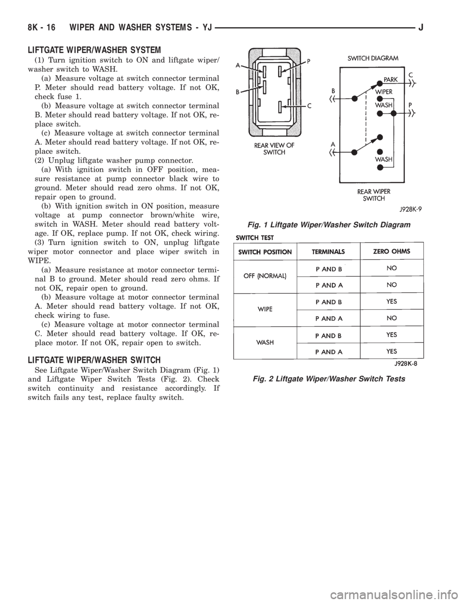
LIFTGATE WIPER/WASHER SWITCH
See Liftgate Wiper/Washer Switch Diagram (Fig. 1)
and Liftgate Wiper Switch Tests (Fig. 2). Check
switch continuity and resistance accordingly. If
switch fails any test, replace faulty switch.
Fig. 1 Liftgate Wiper/Washer Switch Diagram
Fig. 2 Liftgate Wiper/Washer Switch Tests
8K - 16 WIPER AND WASHER SYSTEMS - YJJ
Page 448 of 2198
LAMPS
CONTENTS
page page
BULB APPLICATIONÐXJ VEHICLES......... 18
GENERAL INFORMATION.................. 1INTERIOR LAMPS....................... 16
SERVICE PROCEDURES................... 6
GENERAL INFORMATION
Each vehicle is equipped with various lamp assem-
blies. A good ground is necessary for proper lighting
operation. Grounding is provided by the lamp socket
when it comes in contact with the metal body, or
through a separate ground wire.
When changing lamp bulbs check the socket for
corrosion. If corrosion is present, clean it with a wire
brush and coat the inside of the socket lightly with
Mopar Multi-Purpose Grease or equivalent.
DIAGNOSTIC PROCEDURESÐXJ
When a vehicle experiences problems with the
headlamp system, verify the condition of the batteryconnections, charging system, headlamp bulbs, wire
connectors, relay, high beam dimmer switch and
headlamp switch. Refer to Group 8W, Wiring Dia-
grams for component locations and circuit informa-
tion.
Always begin any diagnosis by testing all of the
fuses and circuit breakers in the system. Refer to
Group 8W, Wiring Diagrams.
JLAMPS 8L - 1
Page 466 of 2198
LAMPS
CONTENTS
page page
BULB APPLICATIONÐYJ VEHICLES......... 32
GENERAL INFORMATION................. 19INTERIOR LAMPS....................... 31
SERVICE PROCEDURES.................. 22
GENERAL INFORMATION
Each vehicle is equipped with various lamp assem-
blies. A good ground is necessary for proper lighting
operation. Grounding is provided by the lamp socket
when it comes in contact with the metal body, or
through a separate ground wire.
When changing lamp bulbs check the socket for
corrosion. If corrosion is present, clean it with a wire
brush and coat the inside of the socket lightly with
Mopar Multi-Purpose Grease or equivalent.
DIAGNOSTIC PROCEDURESÐYJ
When a vehicle experiences problems with the
headlamp system, verify the condition of the batteryconnections, charging system, headlamp bulbs, wire
connectors, relay, high beam dimmer switch and
headlamp switch. Refer to Group 8W, Wiring Dia-
grams for component locations and circuit informa-
tion.
Always begin any diagnosis by testing all of the
fuses and circuit breakers in the system. Refer to
Group 8W, Wiring Diagrams.
JLAMPSÐYJ VEHICLES 8L - 19
Page 484 of 2198
REAR WINDOW DEFOGGER
CONTENTS
page page
DIAGNOSIS............................. 1
GENERAL INFORMATION.................. 1SERVICE PROCEDURES................... 3
GENERAL INFORMATION
The electrically-heated rear window defogger is an
available option on XJ (Cherokee), and YJ (Wrangler)
models equipped with the hardtop roof option. Fol-
lowing are general descriptions of the major compo-
nents in the rear window defogger system. Refer to
Group 8W - Wiring Diagrams for complete circuit de-
scriptions and diagrams.
REAR WINDOW GLASS GRID
The heated rear window glass has two electrically-
conductive vertical bus bars and a series of horizon-
tal grid lines made of a silver-ceramic material,
which is baked on and bonded to the inside surface of
the glass. The grid lines and bus bars comprise a
parallel electrical circuit.
When the rear window defogger switch is placed in
the ON position, current is directed to the rear win-
dow grid lines through the bus bars. The grid lines
heat the rear window to clear the surface of fog or
snow. Circuit protection for the heated grid circuit is
provided by fuse 18 (XJ) or fuse 6 (YJ) in the fuse-
block module.
The grid lines and bus bars are highly resistant to
abrasion. However, it is possible for an open to occur
in an individual grid line resulting in no current flow
through the line. The grid lines can be damaged or
scraped off with sharp instruments. Care should be
taken in cleaning the glass or removing foreign ma-
terials, decals or stickers. Normal glass cleaning sol-
vents or hot water used with rags or toweling is
recommended.A repair kit is available to repair the grid lines and
bus bars, or to reinstall the heated glass pigtail
wires.
DEFOGGER SWITCH
The rear window defogger switch is mounted in the
instrument panel left of the steering column for XJ,
or right of the steering column for YJ. The switch cir-
cuit is protected by fuse 8 (XJ) or fuse 9 (YJ) in the
fuseblock module. Actuating the switch energizes the
relay and electronic timer. A light-emitting diode
(LED) in the switch (XJ), or a indicator lamp in the
switch (YJ), illuminates to indicate when the system
is turned on. The defogger switch can not be re-
paired. If faulty, the switch must be replaced.
DEFOGGER RELAY/TIMER
The defogger relay/timer is located in the relay cen-
ter on XJ models, or taped to the instrument panel
wiring harness behind the parking brake pedal in the
left cowl side area on YJ models. When the rear de-
fogger switch is actuated, the rear defogger relay is
energized. This causes current to flow through the
grid circuit for approximately 10 minutes, or until
the rear window defogger switch or ignition switch
are turned off.
DIAGNOSIS
SYSTEM TESTS
Electrically-heated rear window defogger operation
can be confirmed in the following manner:
(1) Turn the ignition switch to the ON position.
(2) Turn rear window defogger control switch ON.
(3) Monitor vehicle voltmeter. With the control
switch ON, a distinct needle deflection should be
noted.(4) The rear window defogger operation can be
checked by feeling the glass. A distinct difference in
temperature between the grid lines and adjacent
clear glass can be detected within 3 to 4 minutes of
operation.
(5) Using a DC voltmeter, contact terminal A (Fig.
1) (passenger side) with the negative lead, and termi-
JREAR WINDOW DEFOGGER 8N - 1
Page 486 of 2198
DEFOGGER SWITCH
With defogger switch connector separated from de-
fogger switch; turn ignition switch to ON for voltage
tests, or turn ignition switch to OFF for resistance
tests.
(1) Measure voltage at defogger switch connector
terminal D. The meter should read approximately 5
volts momentarily. If OK, go to next step. If not OK,
repair open from relay.
(2) Refer to switch diagram for resistance tests. If
not OK, replace defogger switch.
DEFOGGER RELAY
With defogger relay connector separated from de-
fogger relay; turn ignition switch to ON for voltage
tests, or turn ignition switch to OFF for resistance
tests.
(1) Measure voltage at relay connector terminal 4.
The meter should read battery voltage. If OK, go to
next step. If not OK, repair open from fuse 18 (XJ) or
fuse 9 (YJ).(2) Measure voltage at relay connector terminal 5.
The meter should read battery voltage. If OK, go to
next step. If not OK, repair open from fuse 8 (XJ), or
fuse 6 (YJ).
(3) Measure resistance between relay connector
terminal 1 and left side (driver's side) of defogger
grid. The meter should read zero ohms. If OK, go to
next step. If not OK, repair open between relay con-
nector and left side of defogger grid.
(4) Measure resistance between relay connector
terminal 2 and a clean chassis ground. The meter
should read zero ohms. If OK, go to next step. If not
OK, repair open between relay connector and ground.
(5) Connect relay connector and measure voltage
at terminal 3. The meter should read approximately
5 volts. If not OK, replace defogger relay.
SERVICE PROCEDURES
REAR WINDOW GLASS GRID REPAIRS
The repair of grid lines, bus bars or pigtail wires
can be accomplished using the MOPAR Rear Window
Defogger Repair Kit (P/N 4267922) or equivalent.
WARNING: MATERIALS CONTAINED IN REPAIR KIT
MAY CAUSE SKIN OR EYE IRRITATION. CONTAINS
EPOXY RESIN AND AMINE TYPE HARDENER,
HARMFUL IF SWALLOWED. AVOID CONTACT WITH
SKIN AND EYES. FOR SKIN, WASH AFFECTED AR-
EAS WITH SOAP AND WATER. DO NOT TAKE IN-
TERNALLY. IF TAKEN INTERNALLY, INDUCE
VOMITING; CALL A PHYSICIAN IMMEDIATELY. IF IN
CONTACT WITH EYES, FLUSH WITH PLENTY OF
WATER. USE WITH ADEQUATE VENTILATION. DO
NOT USE NEAR FIRE OR FLAME. CONTENTS CON-
TAIN 3% FLAMMABLE SOLVENTS. KEEP OUT OF
REACH OF CHILDREN.
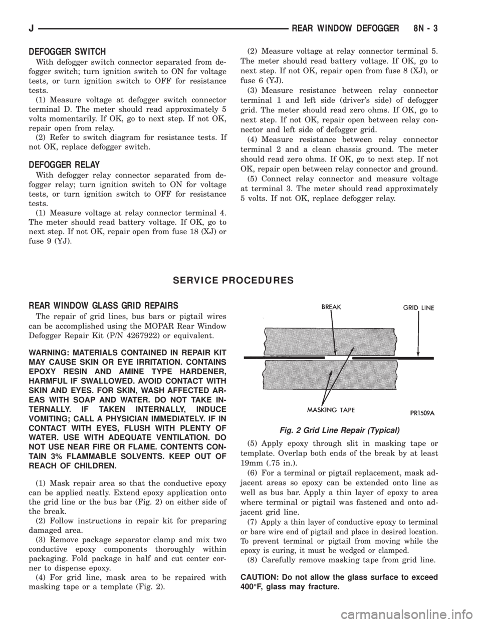
(1) Mask repair area so that the conductive epoxy
can be applied neatly. Extend epoxy application onto
the grid line or the bus bar (Fig. 2) on either side of
the break.
(2) Follow instructions in repair kit for preparing
damaged area.
(3) Remove package separator clamp and mix two
conductive epoxy components thoroughly within
packaging. Fold package in half and cut center cor-
ner to dispense epoxy.
(4) For grid line, mask area to be repaired with
masking tape or a template (Fig. 2).(5) Apply epoxy through slit in masking tape or
template. Overlap both ends of the break by at least
19mm (.75 in.).
(6) For a terminal or pigtail replacement, mask ad-
jacent areas so epoxy can be extended onto line as
well as bus bar. Apply a thin layer of epoxy to area
where terminal or pigtail was fastened and onto ad-
jacent grid line.
(7) Apply a thin layer of conductive epoxy to terminal
or bare wire end of pigtail and place in desired location.
To prevent terminal or pigtail from moving while the
epoxy is curing, it must be wedged or clamped.
(8) Carefully remove masking tape from grid line.
CAUTION: Do not allow the glass surface to exceed
400ÉF, glass may fracture.
Fig. 2 Grid Line Repair (Typical)
JREAR WINDOW DEFOGGER 8N - 3