1995 JEEP CHEROKEE Stop light
[x] Cancel search: Stop lightPage 414 of 2198
TURN SIGNAL AND HAZARD WARNING SYSTEMS
CONTENTS
page page
DIAGNOSIS............................. 3
GENERAL INFORMATION.................. 1SERVICE PROCEDURES................... 5
GENERAL INFORMATION
Following are general descriptions of the major
components in the XJ (Cherokee)/YJ (Wrangler)
model turn signal and hazard warning systems. Refer
to Group 8W - Wiring Diagrams for complete circuit
descriptions and diagrams.
TURN SIGNAL SYSTEM
With the ignition switch in the ON or ACCESSORY
position and the turn signal switch lever (YJ) or
multi-function switch control lever (XJ) moved up
(right turn) or down (left turn), the turn signal sys-
tem is activated.
When the turn signal system is activated, the se-
lected (right or left) turn signal indicator lamp, front
park/turn signal lamp and rear tail/stop/turn signal
lamp bulb filaments will flash. With the headlamp
switch in the OFF position, the turn and front side
marker lamps flash in unison. With the headlamp
switch in the ON position, the turn and front side
marker lamps flash alternately.
HAZARD WARNING SYSTEM
The hazard warning is activated by a switch button
located below the ignition lock cylinder (YJ) or on the
top of the steering column (XJ) between the steering
wheel and the instrument panel. The hazard warning
flasher (YJ) or combination flasher (XJ) receives bat-
tery feed at all times, and the system is functional
regardless of ignition switch position. The hazard
warning switch button is identified with a double
triangle. On YJ models, push the switch button in to
activate the hazard warning system and pull the
button out to turn system off. On XJ models, push in
on the switch button to latch the switch and activate
the hazard warning system, and push in on the
switch button again to unlatch the switch and turn
the system off.
When the hazard warning system is activated, all
(right and left) turn signal indicator, front park/turn
signal lamp and rear tail/stop/turn signal lamp bulb
filaments will flash.
TURN SIGNAL FLASHER (YJ ONLY)
The turn signal flasher is located in the fuseblock
module. It contains one fixed contact point and one
contact point attached to a flexible bimetal arm. The
contact points are normally closed. When a turn sig-
nal is activated, current flows through the flasher. As
current flows through the bimetal arm it heats and
flexes to pull the contact points open, stopping cur-
rent flow. As the bimetal arm cools it straightens,
until the contact points close and the cycle repeats.
The standard flasher is designed to handle the cur-
rent flow requirements of the factory installed light-
ing. If supplemental lighting is added to the turn
signal circuits such as when towing a trailer with
lights, the current flow through the flasher increases.
This causes the flash rate to increase. It is recom-
mended that the standard flasher be replaced with a
heavy-duty (hazard warning) flasher when supple-
mental lighting is added.
However, when a turn signal bulb fails with a stan-
dard flasher, the remaining bulbs in that circuit will
light, but not flash. This will give the driver an indi-
cation to check the turn signal bulbs. Because a
heavy-duty flasher has different internal circuitry, a
failed bulb will not prevent the remaining bulbs in
the circuit from flashing. Therefore, it is recom-
mended that an occasional visual inspection of exte-
rior turn signal lamp operation be performed when a
heavy-duty flasher is installed.
HAZARD WARNING FLASHER (YJ ONLY)
The hazard warning flasher is located in the fuse-
block module. The hazard warning flasher contains
two normally open contact points mounted to two
flexible arms. A bimetal strip is attached between the
two arms. When the hazard warning is activated,
current flows through the flasher. As the current
flows through the bimetal strip it heats and pulls the
flexible arms together until the contact points close,
JTURN SIGNAL AND HAZARD WARNING SYSTEMS 8J - 1
Page 415 of 2198
allowing current flow to the lamps. As the bimetal
strip cools, the contact points are pushed open and
the cycle repeats.
COMBINATION FLASHER (XJ ONLY)
The combination flasher functions as both the turn
signal and hazard warning flasher on XJ models. The
combination flasher is a smart relay that is located in
the relay center under the lower instrument panel
and inboard of the steering column. The combination
flasher can not be repaired. If faulty, it must be
replaced.
The combination flasher is designed to handle the
current flow requirements of the factory installed
lighting. If supplemental lighting is added to the turn
signal circuits such as when towing a trailer with
lights, the combination flasher will automatically
compensate. This allows the flash rate to remain the
same, regardless of electrical load increases. However,
if a bulb fails in the turn signal or hazard warning
circuits, the flash rate of the remaining bulbs in that
circuit will increase to 120 flashes per minute or
higher.
TURN SIGNAL/HAZARD WARNING SWITCH
(YJ ONLY)
The turn signal and hazard warning switches are
combined into a single unit mounted within the upper
steering column bowl and beneath the steering wheel.
The turn signal lever on the left side of the steering
column is moved up or down to select the right or left
turn signal switch position. The turn signals will only
operate with the ignition switch in the ACCESSORY
or ON position.
The hazard warning button on the right side of the
steering column is pushed in to turn the hazard
warning system on, or pulled out to turn the system
off. The hazard warning system will operate regard-
less of ignition switch position. The turn signal/haz-
ard warning switch can not be repaired. If faulty, the
entire unit must be replaced.
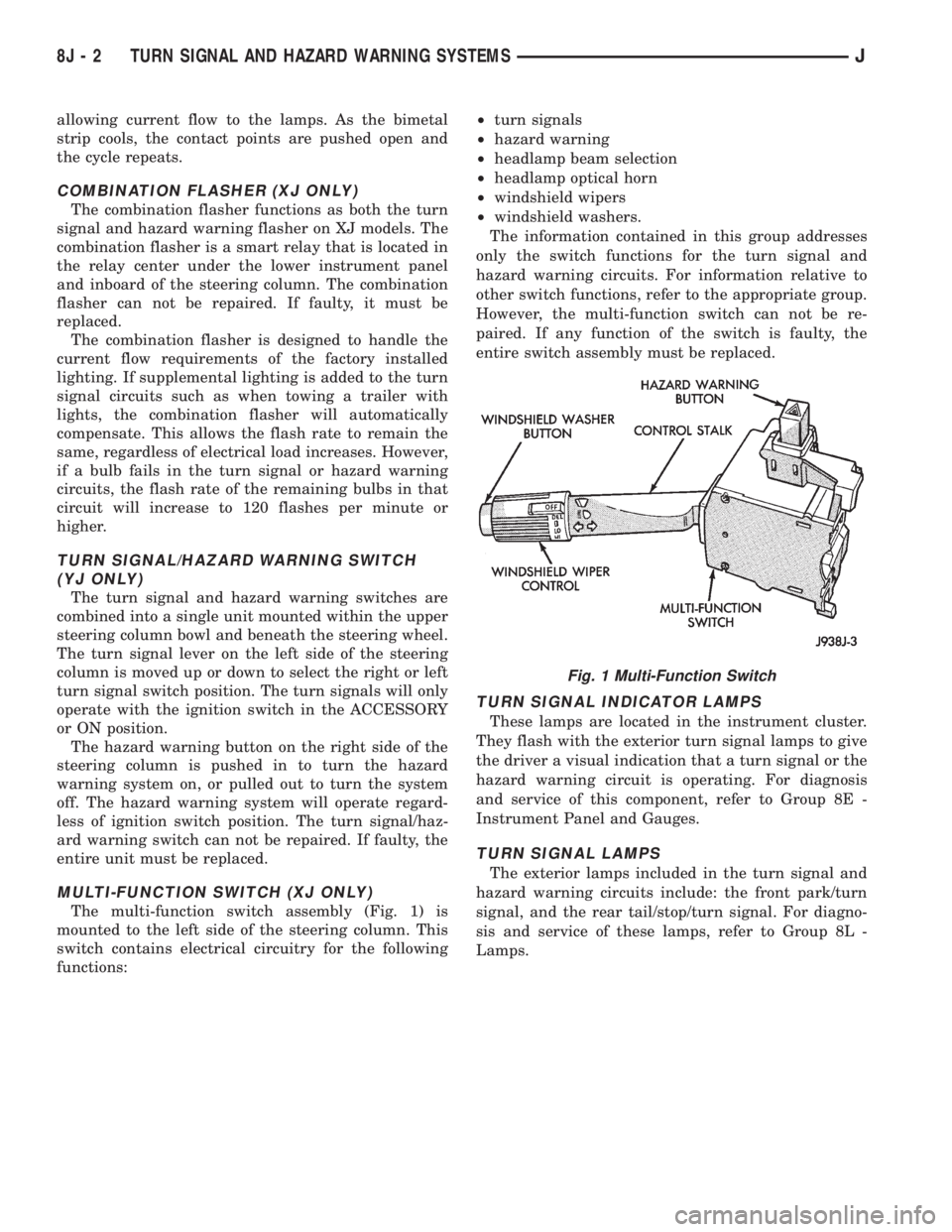
MULTI-FUNCTION SWITCH (XJ ONLY)
The multi-function switch assembly (Fig. 1) is
mounted to the left side of the steering column. This
switch contains electrical circuitry for the following
functions:²turn signals
²hazard warning
²headlamp beam selection
²headlamp optical horn
²windshield wipers
²windshield washers.
The information contained in this group addresses
only the switch functions for the turn signal and
hazard warning circuits. For information relative to
other switch functions, refer to the appropriate group.
However, the multi-function switch can not be re-
paired. If any function of the switch is faulty, the
entire switch assembly must be replaced.
TURN SIGNAL INDICATOR LAMPS
These lamps are located in the instrument cluster.
They flash with the exterior turn signal lamps to give
the driver a visual indication that a turn signal or the
hazard warning circuit is operating. For diagnosis
and service of this component, refer to Group 8E -
Instrument Panel and Gauges.
TURN SIGNAL LAMPS
The exterior lamps included in the turn signal and
hazard warning circuits include: the front park/turn
signal, and the rear tail/stop/turn signal. For diagno-
sis and service of these lamps, refer to Group 8L -
Lamps.
Fig. 1 Multi-Function Switch
8J - 2 TURN SIGNAL AND HAZARD WARNING SYSTEMSJ
Page 453 of 2198
SERVICE PROCEDURES
INDEX
page page
Back-Up/Rear Turn Signal/Tail Lamp Bulb
ReplacementÐXJ....................... 12
Center High Mounted Stop Lamp (CHMSL)ÐXJ . . 12
Daytime Running Lights (Canada Only)ÐXJ..... 15
Drl Module ReplacementÐXJ................ 15
Fog Lamp ReplacementÐXJ.................. 9
Fog Lamp Switch ReplacementÐXJ........... 10
Fog LampsÐXJ........................... 7
Front Park/Turn Signal Lamp Bulb
ReplacementÐXJ........................ 9
Headlamp Alignment PreparationÐXJ........... 6
Headlamp AlignmentÐXJ.................... 6
Headlamp Bulb ReplacementÐXJ.............. 7Headlamp Delay Function Trouble DiagnosisÐXJ . 14
Headlamp Delay Module ReplacementÐXJ...... 14
Headlamp SwitchÐXJ...................... 10
Headlamp/Fog Lamp Adjustment Using Alignment
ScreenÐXJ............................. 7
License Plate LampÐXJ.................... 12
Multi-Function Switch Service ProceduresÐXJ.... 11
Sentinel Headlamp Delay ModuleÐXJ.......... 14
Side Marker Lamp Bulb ReplacementÐXJ....... 10
Underhood Lamp Bulb ReplacementÐXJ....... 13
Underhood Lamp ReplacementÐXJ........... 13
Underhood Lamp Service InformationÐXJ....... 12
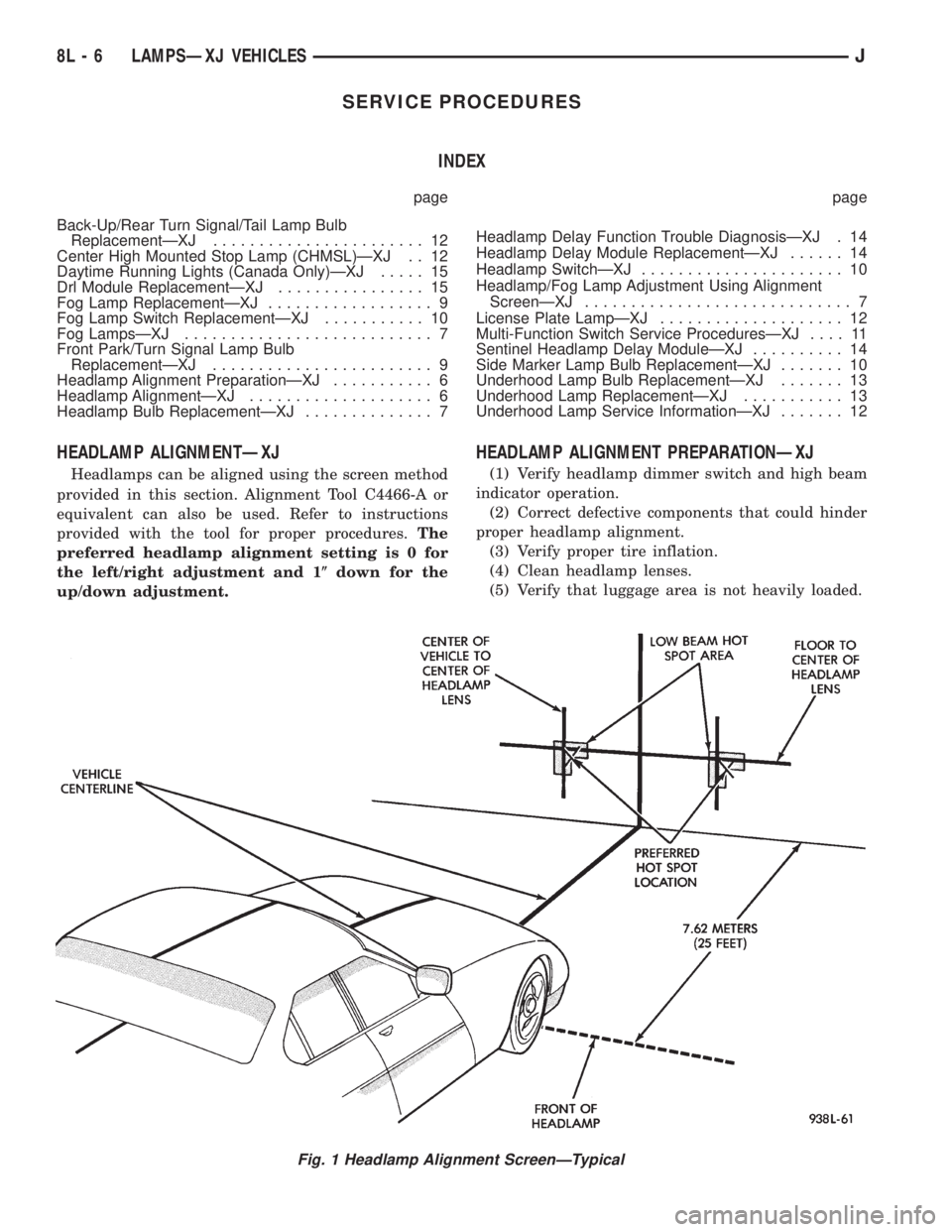
HEADLAMP ALIGNMENTÐXJ
Headlamps can be aligned using the screen method
provided in this section. Alignment Tool C4466-A or
equivalent can also be used. Refer to instructions
provided with the tool for proper procedures.The
preferred headlamp alignment setting is 0 for
the left/right adjustment and 1(down for the
up/down adjustment.
HEADLAMP ALIGNMENT PREPARATIONÐXJ
(1) Verify headlamp dimmer switch and high beam
indicator operation.
(2) Correct defective components that could hinder
proper headlamp alignment.
(3) Verify proper tire inflation.
(4) Clean headlamp lenses.
(5) Verify that luggage area is not heavily loaded.
Fig. 1 Headlamp Alignment ScreenÐTypical
8L - 6 LAMPSÐXJ VEHICLESJ
Page 465 of 2198
BULB APPLICATIONÐXJ VEHICLES
GENERAL INFORMATION
The following Bulb Application Table lists the lamp
title on the left side of the column and trade number
or part number on the right.
CAUTION: Do not use bulbs that have a higher can-
dle power than the bulb listed in the Bulb Applica-
tion Table. Damage to lamp can result.
Do not touch halogen bulbs with fingers or other
oily surfaces. Bulb life will be reduced.
EXTERIOR LAMPSÐXJ
Back-up .................................................................1156
Center High Mounted Stoplamp ..........................922
Fog ............................................................................H3
Front Side Marker .................................................194
Headlamp/Sealed Beam....................................H6054
License Plate ..........................................................168
License Plate W/Outside Spare ..............................67
Park/Turn Signal ............................................2057NA
Tail/Stop ................................................................2057
Turn Signal ...........................................................1156
INTERIOR LAMPSÐXJ
Service procedures for most of the lamps in the in-
strument panel, Instrument cluster and switches are
located in Group 8E, Instrument Panel and Gauges.
Some components have lamps that can only be ser-
viced by an Authorized Service Center (ASC) after
the component is removed from the vehicle. Contact
local dealer for location of nearest ASC.
Cargo .......................................................................561
Dome .......................................................................561
Dome/Reading.........................................................906Glove Compartment ...............................................194
Overhead Console ..................................................912
Under Hood ............................................................105
Vanity Mirror ...........................................................74
Underpanel Courtesy.............................................168
INDICATOR LAMPS
Service procedures for most of the lamps in the in-
strument panel, instrument cluster and switches are
located in Group 8E, Instrument Panel and Gauges.
A/C Control ...............................................................74
Airbag ........................................................................74
Anti-lock Brake ........................................................74
Ash Receiver .........................................................1891
Brake Warning .........................................................74
Check Engine ...........................................................74
Cigar Lighter ............................................................53
Diesel Wait ...............................................................74
Fasten Seat Belts ....................................................74
Four Wheel Drive ....................................................74
Generator ................................................................194
Generator/Diesel.......................................................74
Heater Control .........................................................74
High Beam..............................................................194
Illumination ............................................................194
Low Fuel .................................................................194
Low Washer Fluid....................................................74
Radio ......................................................................ASC
Rocker Switch...........................................................37
Seat Belt ...................................................................74
Transfer Case .........................................................658
Transmission Floor Shift.......................................658
Turn Signal.............................................................194
Shift ...........................................................................74
Water In Fuel ...........................................................74
8L - 18 LAMPSÐXJ VEHICLESJ
Page 469 of 2198
SERVICE PROCEDURES
INDEX
page page
Back-Up/Rear Turn Signal/Tail Lamp Bulb
ReplacementÐYJ....................... 28
Center High Mounted Stop Lamp (CHMSL)ÐYJ . . 28
Daytime Running Lights (Canada Only)ÐYJ..... 30
Drl Module ReplacementÐYJ................ 30
Fog Lamp ReplacementÐYJ................. 25
Fog Lamp Switch ReplacementÐYJ........... 26
Fog LampsÐYJ.......................... 23
Front Park/Turn Signal Lamp Bulb ReplacementÐ
YJ ................................... 25
Headlamp Alignment PreparationÐYJ.......... 22Headlamp AlignmentÐYJ................... 22
Headlamp Bulb ReplacementÐYJ............. 23
Headlamp Dimmer Switch ReplacementÐYJ..... 26
Headlamp SwitchÐYJ...................... 26
Headlamp/Fog Lamp Adjustment Using Alignment
ScreenÐYJ............................ 23
Side Marker Lamp Bulb ReplacementÐYJ....... 25
Underhood Lamp Bulb ReplacementÐYJ....... 29
Underhood Lamp ReplacementÐYJ........... 29
Underhood Lamp Service InformationÐYJ....... 28
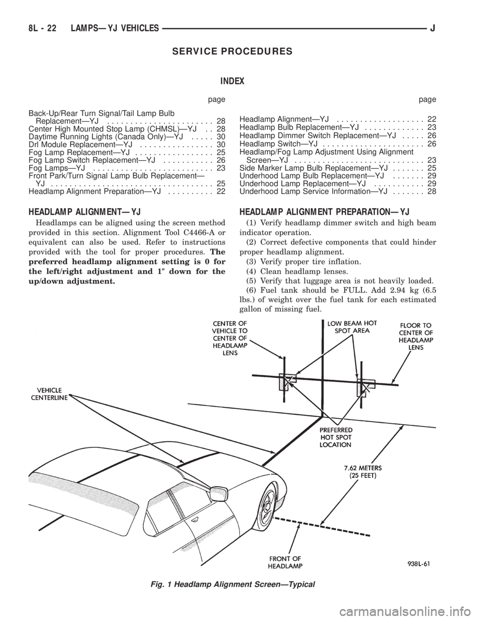
HEADLAMP ALIGNMENTÐYJ
Headlamps can be aligned using the screen method
provided in this section. Alignment Tool C4466-A or
equivalent can also be used. Refer to instructions
provided with the tool for proper procedures.The
preferred headlamp alignment setting is 0 for
the left/right adjustment and 1(down for the
up/down adjustment.
HEADLAMP ALIGNMENT PREPARATIONÐYJ
(1) Verify headlamp dimmer switch and high beam
indicator operation.
(2) Correct defective components that could hinder
proper headlamp alignment.
(3) Verify proper tire inflation.
(4) Clean headlamp lenses.
(5) Verify that luggage area is not heavily loaded.
(6) Fuel tank should be FULL. Add 2.94 kg (6.5
lbs.) of weight over the fuel tank for each estimated
gallon of missing fuel.
Fig. 1 Headlamp Alignment ScreenÐTypical
8L - 22 LAMPSÐYJ VEHICLESJ
Page 479 of 2198

BULB APPLICATIONÐYJ VEHICLES
GENERAL INFORMATION
The following Bulb Application Table lists the lamp
title on the left side of the column and trade number
or part number on the right.
CAUTION: Do not use bulbs that have a higher can-
dle power than the bulb listed in the Bulb Applica-
tion Table. Damage to lamp can result.
Do not touch halogen bulbs with fingers or other
oily surfaces. Bulb life will be reduced.
EXTERIOR LAMPSÐYJ
Back-up .................................................................1156
Center High Mounted Stoplamp ..........................912
Fog ............................................................................H3
Front Side Marker .................................................194
Headlamp/Sealed Beam....................................H6054
Park/Turn Signal..................................................3157
Tail/Stop ................................................................1157
INTERIOR LAMPSÐYJ
Service procedures for most of the lamps in the in-
strument panel, Instrument cluster and switches are
located in Group 8E, Instrument Panel and Gauges.
Some components have lamps that can only be ser-
viced by an Authorized Service Center (ASC) after
the component is removed from the vehicle. Contact
local dealer for location of nearest ASC.Dome/Cargo .........................................................212-2
Glove Compartment ...............................................194
Under Hood ............................................................105
Underpanel Courtesy...............................................89
INDICATOR LAMPS
Service procedures for most of the lamps in the in-
strument panel, instrument cluster and switches are
located in Group 8E, Instrument Panel and Gauges.
A/C Control ...............................................................74
Anti-lock Brake ........................................................74
Ash Receiver .........................................................1891
Brake Warning .........................................................74
Cigar Lighter ............................................................53
Fasten Seat Belts ....................................................74
Four Wheel Drive ....................................................74
Generator ................................................................194
Hazard.......................................................................74
Heater Control .......................................................194
High Beam..............................................................194
Illumination ............................................................194
Low Coolant..............................................................74
Radio ......................................................................ASC
Rocker Switch...........................................................74
Seat Belt ...................................................................74
Shift ...........................................................................74
Turn Signal.............................................................194
8L - 32 LAMPSÐYJ VEHICLESJ
Page 504 of 2198
POWER WINDOWS
CONTENTS
page page
DIAGNOSIS............................. 1
GENERAL INFORMATION.................. 1SERVICE PROCEDURES................... 7
GENERAL INFORMATION
Power door windows are optional equipment on XJ
(Cherokee) models. The power windows operate only
with the ignition switch in the ON position. This
group covers diagnosis and service of the electrical
components peculiar to the power window system.
For service of mechanical components such as the
regulator, lift plate or window tracks refer to Group
23 - Body Components.
Following are general descriptions of the major
components in the power window system. Refer to
Group 8W - Wiring Diagrams for complete circuit de-
scriptions and diagrams.
POWER WINDOW SWITCH
Both front and rear door windows can be raised or
lowered electrically by operating the four two-way
switches on the driver's door panel. A single two-way
switch on each passenger's door panel operates only
the window on that passenger's door. The switches
cannot be repaired. If faulty, they must be replaced.
POWER WINDOW MOTOR
A permanent magnet reversible motor moves the
window regulator through a cable and drum operat-ing mechanism. A positive and negative battery con-
nection to the two motor terminals will cause the
motor to rotate in one direction. Reversing current
through these same two connections will cause the
motor to rotate in the opposite direction. In addition,
each power window motor is equipped with an inte-
gral automatic re-setting circuit breaker to protect
the motor from overloads. The power window motor
and regulator assembly cannot be repaired. If faulty,
the entire assembly must be replaced.
CIRCUIT BREAKER
An automatic re-setting circuit breaker in the fuse-
block module is used to protect the power window
system circuit. The circuit breaker can protect the
system from a short circuit, and can also protect the
system from an overload condition caused by an ob-
structed or stuck window glass or regulator. The cir-
cuit breaker can not be repaired. If faulty, it must be
replaced.
DIAGNOSIS
It is necessary that the window be free to slide up
and down for the power window system to function
properly. If the window is not free to move up and
down, the motor will overload and trip the circuit
breaker. To determine if the glass is free, disconnect
regulator plate from the glass and slide window up
and down by hand.
An alternate method is to shake the glass in the
door, with the glass positioned between the up and
down stop positions. Check that the glass can be
moved slightly from side to side, front to rear, and up
and down. Then check that window is not boundtight in the tracks. If window is free, proceed with di-
agnosis that follows. If window is not free, refer to
Group 23 - Body Components for service procedures.
CIRCUIT BREAKER
Locate correct circuit breaker in fuseblock module.
Pull out slightly, but be sure that circuit breaker ter-
minals still contact terminals in fuseblock module.
Turn ignition switch to ON position. Connect ground
wire of voltmeter to a good ground. With probe of
voltmeter positive lead, check both terminals of cir-
cuit breaker for battery voltage. If only one terminal
JPOWER WINDOWS 8S - 1
Page 661 of 2198
Circuit L39 supplies voltage to the fog lamps. Cir-
cuit Z1 provides ground for the fog lamps.
If the high beam lamps are ON, circuit G465 ener-
gizes the high beam relay. When the high beam relay
energizes, the contacts open and power is not sup-
plied to the fog lamps. Circuit Z1 provides ground for
the coil side of the high beam relay.
Circuit E2 provides voltage for the illumination
lamp in the fog lamp switch.
HELPFUL INFORMATION
²Circuit L3 splices to power circuit G465. Circuit
L3 powers the high beam circuit of the headlamps.
HEADLAMP DELAY MODULE
When the operator turns off the ignition switch and
the headlamp switch, the headlamp delay module
powers the headlamps for approximately 45 seconds.
When the ignition switch is in the RUN position,
circuit A21 powers circuit F87 through fuse 17 in the
fuse block. Circuit F87 supplies the IGNITION ON/
OFF signal to the headlamp delay module. Circuit Z1
provides ground for the module.
When the headlamp delay module activates, it con-
nects circuit X4 from fuse 11 in the fuse block to cir-
cuit F34. Circuit F34 powers the headlamps through
the headlamp dimmer switch circuit L3.
HELPFUL INFORMATION
Circuit A7 from fuse 3 in the PDC supplies voltage
to the fuse block bus bar that powers circuit X4
through the fuse in cavity 11.
DAYTIME RUNNING LAMP (DRL) MODULE
On vehicles built for sale in Canada, the low-beam
headlamps operate when the ignition switch is in the
RUN position.
When the ignition switch is in the RUN position,
circuit A1 from fuse 6 in the Power Distribution Cen-
ter (PDC), connects to circuit A21. Circuit A21 splices
to supply power to the DRL module.
Circuit A3 from fuse 5 in the PDC connects to DRL
module. Circuit A3 is HOT at all times.The DRL module receives the vehicle speed sensor
input from circuit G7. Circuit G465 from the DRL
module splices to circuit L3 to provide power for the
high beam indicator lamp in the instrument cluster.
Circuit L4 powers the low beams of the left and
right headlamps. When the headlamp switch is OFF,
the DRL module powers the low beams on circuit L4.
When the headlamps are ON, the dimmer switch in
the multi-function switch powers the low beams on
circuit L4.
Circuit L3 feeds the high beams of the headlamps.
When the operator flashes the headlamps with the
stalk of the multi-function switch, the DRL senses
voltage on circuit L3. When it senses voltage on cir-
cuit L3, the DRL module stops supplying power to
the low beams on circuit L4.
Circuit Z12 provides ground for the DRL module.
DIAGRAM INDEX
Component Page
Chime/Buzzer Module......................8W-50-8
Daytime Running Lamps (DRL) Module..........8W-50-3
Fog Lamps.............................8W-50-7
Fog Lamp Switch........................8W-50-7
Fuse 3 (PDC)...........................8W-50-9
Fuse 4 (Fuse Block).......................8W-50-9
Fuse 5 (PDC).....................8W-50-2, 3, 6, 9
Fuse 6 (PDC).........................8W-50-2, 8
Fuse 7 (PDC)...........................8W-50-6
Fuse 11 (Fuse Block)......................8W-50-9
Fuse 13 (PDC)..........................8W-50-6
Fuse 15 (Fuse Block)....................8W-50-3, 6
Fuse 17 (Fuse Block)......................8W-50-8
Fuse 19 (Fuse Block)......................8W-50-6
Headlamps.............................8W-50-5
Headlamp Dimmer Switch.................8W-50-4, 9
Headlamp Switch.....................8W-50-4, 6, 9
High Beam Relay.........................8W-50-7
Ignition Switch........................8W-50-3, 8
Park Lamp Relay.........................8W-50-6
Side Marker Lamps.......................8W-50-5
Tail, Stop and Turn Signal Lamps..............8W-50-5
Telltale Connector (Instrument Cluster)...........8W-50-9
8W - 50 - 2 8W-50 FRONT LIGHTINGÐXJ VEHICLESJ