1995 JEEP CHEROKEE FLASH RELAY
[x] Cancel search: FLASH RELAYPage 1973 of 2198

GENERAL INFORMATION; POWER LOCKS . . 8P-1
GENERAL INFORMATION; POWER
MIRRORS...........................8T-1
GENERAL INFORMATION; POWER SEATS . . 8R-1
GENERAL INFORMATION; POWER
WINDOWS...........................8S-1
GENERAL INFORMATION; PROPELLER
SHAFTS.............................16-1
GENERAL INFORMATION; REAR
SUSPENSION AND AXLES........3-13,3-1,3-9
GENERAL INFORMATION; REAR
WINDOW DEFOGGER..................8N-1
GENERAL INFORMATION; RESTRAINT
SYSTEMS...........................8M-1
GENERAL INFORMATION; SPLICE
INFORMATION (XJ).................8W-70-1
GENERAL INFORMATION; SPLICE
INFORMATION (XJ-RHD)............8W-70-1
GENERAL INFORMATION; SPLICE
INFORMATION (YJ).................8W-70-1
GENERAL INFORMATION; SPLICE
LOCATIONS (XJ)...................8W-95-1
GENERAL INFORMATION; SPLICE
LOCATIONS (XJ-RHD)...............8W-95-1
GENERAL INFORMATION; SPLICE
LOCATIONS (YJ)...................8W-95-1
GENERAL INFORMATION; STEERING . 19-48,19-1
GENERAL INFORMATION;
TRANSMISSION AND TRANSFER CASE . . 21-165,
21-283,21-307,21-33,21-67,21-70,21-1
GENERAL INFORMATION; TURN SIGNAL
AND HAZARD WARNING SYSTEMS.......8J-1
GENERAL INFORMATION; VEHICLE
SPEED CONTROL SYSTEM..............8H-1
GENERAL INFORMATION; WHEELS AND
TIRES..........................22-1,22-6
GENERAL INFORMATION - XJ............8K-1
GENERAL INFORMATION - YJ...........8K-10
GENERAL SERVICE INFORMATION; BODY
COMPONENTSÐXJ VEHICLES.........23-102
GENERAL SERVICE INFORMATION;
BRAKES.........................5-15,5-60
GENERAL SERVICEÐXJ, STEERING
COLUMN...........................19-47
GENERAL SPECIFICATIONS, 30RH/32RH . 21-335
GENERAL SPECIFICATIONS, AW-4......21-337
GENERATOR.........................8B-6
GENERATOR DIAGNOSTIC TROUBLE
CODE..............................8A-22
GENERATOR FIELDÐPCM OUTPUT......14-27
GENERATOR LAMPÐPCM OUTPUT......14-27
GENERATOR RATINGS................8A-23
GENERATOR REMOVE/INSTALLÐLEFT-
HAND DRIVE.........................8B-6
GENERATOR REMOVE/INSTALLÐRIGHT-
HAND DRIVE.........................8B-7
GENERATOR SPECIFICATIONS...........8B-8
GENERATOR SPLASH SHIELD...........13-13
GLASS AND DOOR OPENING
WEATHERSTRIP SEALSÐXJ, DOOR
WINDOW...........................23-55
GLASS CHANNEL REPLACEMENTÐYJ,
DOOR FRAME......................23-142
GLASS GRID, REAR WINDOW.......8N-1,8N-2
GLASS GRID REPAIRS, REAR WINDOW . . . 8N-3
GLASS REGULATOR HANDLEÐYJ,
FULL-METAL DOOR WINDOW..........23-136
GLASS REGULATORÐXJ, FRONT DOOR
WINDOW...........................23-42
GLASS REGULATORÐXJ, REAR DOOR
WINDOW...........................23-44
GLASS REGULATORÐYJ, FULL-METAL
DOOR WINDOW....................23-138
GLASS REPLACEMENTÐXJ,
WINDSHIELD........................23-69
GLASS, STATIONARY.................23-144
GLASS, STATIONARY WINDOW..........23-66
GLASS WATER LEAK DETECTION AND
REPAIRÐXJ, STATIONARY.............23-76
GLASS WATER LEAK DETECTION AND
REPAIRÐYJ, STATIONARY............23-150
GLASS WEATHERSTRIP SEAL
REPLACEMENTÐYJ, LIFTGATE
.........23-125
GLASSÐXJ, FRONT DOOR WINDOW
.....23-43
GLASSÐXJ, LIFTGATE WINDOW
........23-74
GLASSÐXJ, REAR DOOR STATIONARY
WINDOW
...........................23-46
GLASSÐXJ, REAR DOOR WINDOW
......23-45GLASSÐXJ, REAR QUARTER VENT
WINDOW...........................23-73
GLASSÐYJ, FULL-METAL DOOR VENT
WINDOW..........................23-137
GLASSÐYJ, FULL-METAL DOOR
WINDOW..........................23-139
GLASSÐYJ, HARD TOP LIFTGATE......23-124
GLASSÐYJ, HARD TOP QUARTER
WINDOW..........................23-149
GLASSÐYJ, WINDSHIELD............23-146
GLASS/REAR QUARTER PLASTIC
INSERTÐXJ, REAR QUARTER
WINDOW...........................23-73
GLOVE BOX LAMP; INTERIOR LIGHTING
(XJ).............................8W-44-1
GLOVE BOX LAMP; INTERIOR LIGHTING
(XJ-RHD).........................8W-44-1
GLOVE BOXÐYJ....................23-152
(GOP)ÐXJ, GRILLE AND GRILLE
OPENING PANEL......................23-3
GOVERNOR AND PARK GEAR OVERHAUL . 21-127
GOVERNOR AND PARK GEAR SERVICE . . 21-105
GRAB, REAR BRAKE....................5-7
GRID, REAR WINDOW GLASS.......8N-1,8N-2
GRID REPAIRS, REAR WINDOW GLASS . . . 8N-3
GRILLE AND GRILLE OPENING PANEL
(GOP)ÐXJ...........................23-3
GRILLE AND SCREENÐXJ, COWL.......23-12
GRILLE AND SCREENÐYJ, COWL......23-109
GRILLE APPLIQUEÐYJ, RADIATOR.....23-104
GRILLE OPENING PANEL (GOP)ÐXJ,
GRILLE.............................23-3
GRILLEÐXJ, AIR EXHAUST............23-25
GROUND CLEARANCE AND RAMP
ANGLE..............................0-11
GROUND, CLUSTER; INSTRUMENT
CLUSTER (XJ).....................8W-40-3
GROUND, CLUSTER; INSTRUMENT
CLUSTER (XJ-RHD)................8W-40-2
GROUND, POWER....................14-24
GROUND, POWER (DEVICE); FUEL/
IGNITION (XJ).....................8W-30-5
GROUND, POWER (DEVICE); FUEL/
IGNITION (YJ).....................8W-30-5
GROUND, POWER (DEVICE); FUEL/
IGNITION (XJ-RHD)................8W-30-5
GROUP, HOW TO USE THIS; WIRING
DIAGRAMS (XJ)......................8W-1
GROUP, HOW TO USE THIS; WIRING
DIAGRAMS (XJ-RHD)..................8W-1
GROUP, HOW TO USE THIS; WIRING
DIAGRAMS (YJ)......................8W-1
GUARD/EDGE PROTECTOR STRIPÐXJ,
DOOR EDGE........................23-54
GUARDÐXJ, BRUSH...................23-3
GUIDES AND CHARTS, DIAGNOSIS......21-77
HALF METAL DOOR MIRROR
(EXTERNAL)ÐYJ....................23-121
HALF-METAL DOOR LATCH STRIKERÐ
YJ ...............................23-135
HALF-METAL SOFT TOP DOORÐYJ.....23-134
HAND DRIVE, AUTOMATIC BELT
TENSIONERÐXJ MODELS WITH
RIGHT..............................7-42
HAND DRIVE, BELT SERVICEÐEXCEPT
RIGHT..............................7-40
HAND DRIVE, BELT SERVICEÐXJ
MODELS WITH RIGHT..................7-42
HAND DRIVE (RHD), BELT TENSIONÐ
EXCEPT RIGHT.......................7-38
HAND DRIVE (RHD), BELT TENSIONÐ
RIGHT..............................7-38
HAND DRIVE (RHD) MODELS, BELT
TENSIONÐEXCEPT RIGHT..............7-45
HAND DRIVE VEHICLES, RIGHT..........23-1
HANDLE COVERÐXJ, PARKING BRAKE . . . 23-94
HANDLEÐXJ, ASSIST.................23-89
HANDLEÐXJ, DOOR EXTERNAL.........23-48
HANDLEÐYJ, FULL-METAL DOOR
ASSIST
...........................23-136
HANDLEÐYJ, FULL-METAL DOOR LATCH
EXTERNAL RELEASE
.................23-140
HANDLEÐYJ, FULL-METAL DOOR LATCH
INSIDE RELEASE AND LOCK
...........23-137
HANDLEÐYJ, FULL-METAL DOOR
WINDOW GLASS REGULATOR
.........23-136
HANDLEÐYJ, TAILGATE LATCH AND
RELEASE
..........................23-122HANDLING, AIRBAG MODULE...........8M-2
HARD PEDAL OR HIGH PEDAL EFFORT.....5-6
HARD TOP LIFTGATE GLASSÐYJ.......23-124
HARD TOP QUARTER WINDOW
GLASSÐYJ........................23-149
HARD TOP REPAIRÐYJ..............23-127
HARD TOP ROOF VENTÐYJ...........23-127
HARD TOPÐYJ.....................23-126
HARDTOP DOME/CARGO LAMP BULB
REPLACEMENTÐYJ VEHICLES..........8L-31
HAS A MISS, INJECTOR DIAGNOSISÐ
VEHICLE RUNS ROUGH AND/OR........14-52
HAZARD FLASHERS; TURN SIGNALS
(XJ).............................8W-52-1
HAZARD FLASHERS; TURN SIGNALS
(XJ-RHD).........................8W-52-1
HAZARD FLASHERS; TURN SIGNALS
(YJ).............................8W-52-1
HAZARD WARNING SYSTEM.............8J-1
HAZARD WARNING SYSTEM - YJ.........8J-4
HCU DIAGNOSIS, ANTILOCK ECU..........5-3
HCU INSTALLATION (XJ)................5-43
HCU INSTALLATION (YJ)................5-44
HCU OPERATION......................5-36
HCU REMOVAL (XJ)...................5-41
HCU REMOVAL (YJ)...................5-44
HEAD COVER, ENGINE CYLINDER....9-22,9-64
HEAD, ENGINE CYLINDER...........9-25,9-67
HEAD GASKET FAILURE DIAGNOSIS,
ENGINE CYLINDER.....................9-5
HEAD NOT REMOVED, VALVE
COMPONENT REPLACEÐCYLINDER . . . 9-23,9-65
HEADLAMP ALIGNMENT
PREPARATIONÐXJ....................8L-6
HEADLAMP ALIGNMENT
PREPARATIONÐYJ...................8L-22
HEADLAMP ALIGNMENTÐXJ............8L-6
HEADLAMP ALIGNMENTÐYJ...........8L-22
HEADLAMP BULB REPLACEMENTÐXJ.....8L-7
HEADLAMP BULB REPLACEMENTÐYJ....8L-23
HEADLAMP DELAY FUNCTION TROUBLE
DIAGNOSISÐXJ.....................8L-14
HEADLAMP DELAY MODULE; FRONT
LIGHTING (XJ)....................8W-50-2
HEADLAMP DELAY MODULE; FRONT
LIGHTING (XJ-RHD)................8W-50-1
HEADLAMP DELAY MODULE
REPLACEMENTÐXJ..................8L-14
HEADLAMP DELAY MODULEÐXJ,
SENTINEL..........................8L-14
HEADLAMP DIAGNOSIS...........8L-20,8L-2
HEADLAMP DIMMER SWITCH
REPLACEMENTÐYJ..................8L-26
HEADLAMP OR PANEL DIMMER SWITCH
REMOVE/INSTALL....................8E-42
HEADLAMP RELAY; FRONT LIGHTING
(XJ-RHD).........................8W-50-1
HEADLAMP SWITCH REMOVE/INSTALL . . . 8E-19
HEADLAMP SWITCH (XJ ONLY)......8U-1,8U-3
HEADLAMP SWITCHÐXJ..............8L-10
HEADLAMP SWITCHÐYJ..............8L-26
HEADLAMP/FOG LAMP ADJUSTMENT
USING ALIGNMENT SCREENÐXJ.........8L-7
HEADLAMP/FOG LAMP ADJUSTMENT
USING ALIGNMENT SCREENÐYJ........8L-23
HEADLAMPS; FRONT LIGHTING (XJ) . . . 8W-50-1
HEADLAMPS; FRONT LIGHTING
(XJ-RHD).........................8W-50-1
HEADLAMPS; FRONT LIGHTING (YJ) . . . 8W-50-1
HEADLAMPS; LUBRICATION AND
MAINTENANCE.......................0-33
HEADLINERÐXJ.....................23-92
HEAT SHIELDS......................14-13
HEAT SHIELDS, EXHAUST...............11-1
HEATED OXYGEN SENSOR; FUEL/
IGNITION (XJ).....................8W-30-3
HEATED OXYGEN SENSOR; FUEL/
IGNITION (YJ).....................8W-30-3
HEATED OXYGEN SENSOR; FUEL/
IGNITION (XJ-RHD)
................8W-30-3
HEATED REAR WINDOW; HEATED REAR
WINDOW (XJ)
.....................8W-48-1
HEATED REAR WINDOW; HEATED REAR
WINDOW (XJ-RHD)
.................8W-48-1
HEATED REAR WINDOW; HEATED REAR
WINDOW (YJ)
.....................8W-48-1
HEATER; AIR CONDITIONING/HEATER
(YJ)
.............................8W-42-1
12 INDEXJ
Description Group-Page Description Group-Page Description Group-Page
Page 2026 of 2198
FUEL/IGNITION
INDEX
page page
Automatic Shut Down (ASD) Relay............. 1
Battery Feed.............................. 2
Brake Switch Input......................... 5
Camshaft Position Sensor.................... 3
Crankshaft Position Sensor................... 3
Data Link Connector........................ 5
Diagram Index............................ 5
Engine Coolant Temperature Sensor............ 3
Fuel Injectors............................. 2
Fuel Pump Module......................... 2
Fuel Pump Relay.......................... 2
Heated Oxygen Sensor...................... 3Idle Air Control (IAC) Motor................... 2
Ignition Coil.............................. 2
Ignition Switch............................ 1
Intake Air Temperature Sensor................ 4
Malfunction Indicator Lamp (MIL)............... 5
Manifold Absolute Pressure Sensor............. 4
Park/Neutral Position Switch.................. 4
Power (Device) Ground...................... 5
Power Steering Pressure Switch............... 4
Tachometer Signal......................... 5
Throttle Position Sensor..................... 4
Vehicle Speed Sensor....................... 3
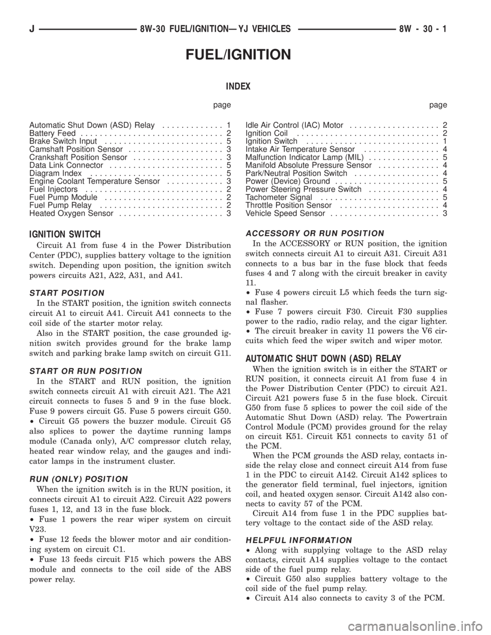
IGNITION SWITCH
Circuit A1 from fuse 4 in the Power Distribution
Center (PDC), supplies battery voltage to the ignition
switch. Depending upon position, the ignition switch
powers circuits A21, A22, A31, and A41.
START POSITION
In the START position, the ignition switch connects
circuit A1 to circuit A41. Circuit A41 connects to the
coil side of the starter motor relay.
Also in the START position, the case grounded ig-
nition switch provides ground for the brake lamp
switch and parking brake lamp switch on circuit G11.
START OR RUN POSITION
In the START and RUN position, the ignition
switch connects circuit A1 with circuit A21. The A21
circuit connects to fuses 5 and 9 in the fuse block.
Fuse 9 powers circuit G5. Fuse 5 powers circuit G50.
²Circuit G5 powers the buzzer module. Circuit G5
also splices to power the daytime running lamps
module (Canada only), A/C compressor clutch relay,
heated rear window relay, and the gauges and indi-
cator lamps in the instrument cluster.
RUN (ONLY) POSITION
When the ignition switch is in the RUN position, it
connects circuit A1 to circuit A22. Circuit A22 powers
fuses 1, 12, and 13 in the fuse block.
²Fuse 1 powers the rear wiper system on circuit
V23.
²Fuse 12 feeds the blower motor and air condition-
ing system on circuit C1.
²Fuse 13 feeds circuit F15 which powers the ABS
module and connects to the coil side of the ABS
power relay.
ACCESSORY OR RUN POSITION
In the ACCESSORY or RUN position, the ignition
switch connects circuit A1 to circuit A31. Circuit A31
connects to a bus bar in the fuse block that feeds
fuses 4 and 7 along with the circuit breaker in cavity
11 .
²Fuse 4 powers circuit L5 which feeds the turn sig-
nal flasher.
²Fuse 7 powers circuit F30. Circuit F30 supplies
power to the radio, radio relay, and the cigar lighter.
²The circuit breaker in cavity 11 powers the V6 cir-
cuits which feed the wiper switch and wiper motor.
AUTOMATIC SHUT DOWN (ASD) RELAY
When the ignition switch is in either the START or
RUN position, it connects circuit A1 from fuse 4 in
the Power Distribution Center (PDC) to circuit A21.
Circuit A21 powers fuse 5 in the fuse block. Circuit
G50 from fuse 5 splices to power the coil side of the
Automatic Shut Down (ASD) relay. The Powertrain
Control Module (PCM) provides ground for the relay
on circuit K51. Circuit K51 connects to cavity 51 of
the PCM.
When the PCM grounds the ASD relay, contacts in-
side the relay close and connect circuit A14 from fuse
1 in the PDC to circuit A142. Circuit A142 splices to
the generator field terminal, fuel injectors, ignition
coil, and heated oxygen sensor. Circuit A142 also con-
nects to cavity 57 of the PCM.
Circuit A14 from fuse 1 in the PDC supplies bat-
tery voltage to the contact side of the ASD relay.
HELPFUL INFORMATION
²Along with supplying voltage to the ASD relay
contacts, circuit A14 supplies voltage to the contact
side of the fuel pump relay.
²Circuit G50 also supplies battery voltage to the
coil side of the fuel pump relay.
²Circuit A14 also connects to cavity 3 of the PCM.
J8W-30 FUEL/IGNITIONÐYJ VEHICLES 8W - 30 - 1
Page 2059 of 2198
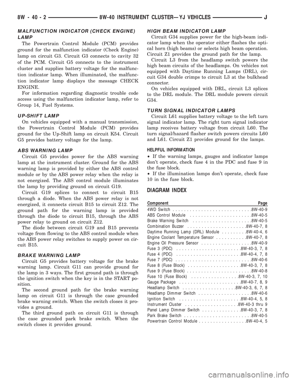
MALFUNCTION INDICATOR (CHECK ENGINE)
LAMP
The Powertrain Control Module (PCM) provides
ground for the malfunction indicator (Check Engine)
lamp on circuit G3. Circuit G3 connects to cavity 32
of the PCM. Circuit G5 connects to the instrument
cluster and supplies battery voltage for the malfunc-
tion indicator lamp. When illuminated, the malfunc-
tion indicator lamp displays the message CHECK
ENGINE.
For information regarding diagnostic trouble code
access using the malfunction indicator lamp, refer to
Group 14, Fuel Systems.
UP-SHIFT LAMP
On vehicles equipped with a manual transmission,
the Powertrain Control Module (PCM) provides
ground for the Up-Shift lamp on circuit K54. Circuit
G5 provides battery voltage for the lamp.
ABS WARNING LAMP
Circuit G5 provides power for the ABS warning
lamp at the instrument cluster. Ground for the ABS
warning lamp is provided by either the ABS control
module or by the ABS power relay when the relay is
not energized. The ABS control module illuminates
the lamp by providing ground on circuit G19.
Circuit G19 splices to connect to circuit B15
through a diode. When the ABS power relay is not
energized, it connects circuit B15 to circuit Z12. The
ground path for the warning lamp is provided
through the diode to circuit B15, through the ABS
power relay to ground on circuit Z12.
The diode between circuit G19 and B15 prevents
voltage from flowing to the ABS control module when
the ABS power relay switches to supply power on cir-
cuit B15.
BRAKE WARNING LAMP
Circuit G5 provides battery voltage for the brake
warning lamp. Circuit G11 can provide ground for
the lamp in 3 ways. The first ground path is through
the ignition switch when the key is in the START po-
sition.
The second ground path for the brake warning
lamp on circuit G11 is through the case grounded
brake warning switch. When the switch closes it pro-
vides a ground.
The third ground path on circuit G11 is through
the case grounded park brake switch. When the
switch closes it provides ground.
HIGH BEAM INDICATOR LAMP
Circuit G34 supplies power for the high-beam indi-
cator lamp when the operator either flashes the opti-
cal horn (high beams) or selects high beam operation.
Circuit Z1 provides the ground path for the lamp.
Circuit L3 from the headlamp switch powers the
high beam circuits of the headlamps. On vehicles not
equipped with Daytime Running Lamps (DRL), cir-
cuit G34 double crimps to circuit L3 at the bulkhead
connector.
On vehicles equipped with DRL, circuit L3 splices
to the DRL module. The DRL module powers circuit
G34.
TURN SIGNAL INDICATOR LAMPS
Circuit L61 supplies battery voltage to the left turn
signal indicator lamp. The right turn signal indicator
lamp receives battery voltage from circuit L60. The
turn signal/hazard flasher switch powers circuits L60
and L61. Circuit Z1 provides ground for the lamps.
HELPFUL INFORMATION
²If the warning lamps, gauges and indicator lamps
don't operate, check fuse 4 in the PDC and fuse 9 in
the fuse block.
²If the illumination lamps don't operate, check fuse
10 in the fuse block.
DIAGRAM INDEX
Component Page
4WD Switch............................8W-40-9
ABS Control Module......................8W-40-5
Brake Warning Switch.....................8W-40-5
Combination Buzzer.....................8W-40-7, 8
Daytime Running Lamp (DRL) Module.........8W-40-4, 6
Engine Coolant Temperature Sensor...........8W-40-7, 8
Engine Oil Pressure Sensor..................8W-40-9
Fuse 3 (PDC).......................8W-40-3, 7, 8
Fuse 4 (PDC).......................8W-40-4, 7, 8
Fuse 7 (PDC)...........................8W-40-6
Fuse 8 (Fuse Block)...................8W-40-3, 7, 8
Fuse 9 (Fuse Block).......................8W-40-8
Fuse 10 (Fuse Block).................8W-40-3, 7, 10
Gauge Package......................8W-40-7, 8, 9
Headlamp Switch...................8W-40-3, 6, 7, 8
Headlamp Dimmer Switch...................8W-40-6
Ignition Switch......................8W-40-4, 5, 8
Instrument Cluster...................8W-40-3 thru 9
Panel Lamp Dimmer Switch..............8W-40-3, 7, 8
Park Brake Switch........................8W-40-5
Powertrain Control Module.................8W-40-4, 5
8W - 40 - 2 8W-40 INSTRUMENT CLUSTERÐYJ VEHICLESJ
Page 2094 of 2198
FRONT LIGHTING
INDEX
page page
Daytime Running Lamp (DRL) ModuleÐCanadian
Vehicles Only........................... 2
Diagram Index............................ 2
Fog Lamps............................... 1Headlamps............................... 1
Parking Lamps............................ 1
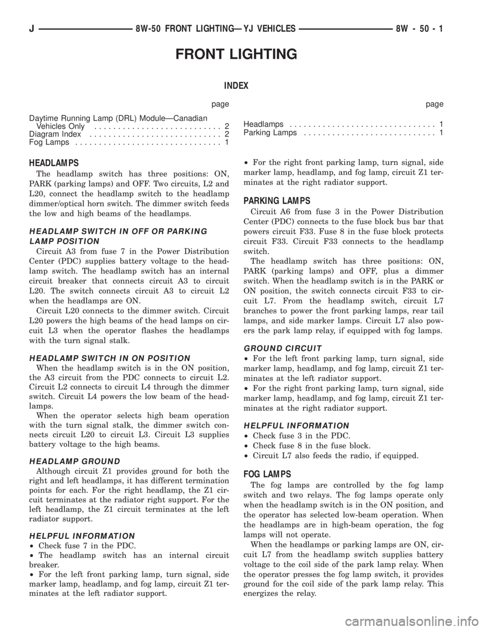
HEADLAMPS
The headlamp switch has three positions: ON,
PARK (parking lamps) and OFF. Two circuits, L2 and
L20, connect the headlamp switch to the headlamp
dimmer/optical horn switch. The dimmer switch feeds
the low and high beams of the headlamps.
HEADLAMP SWITCH IN OFF OR PARKING
LAMP POSITION
Circuit A3 from fuse 7 in the Power Distribution
Center (PDC) supplies battery voltage to the head-
lamp switch. The headlamp switch has an internal
circuit breaker that connects circuit A3 to circuit
L20. The switch connects circuit A3 to circuit L2
when the headlamps are ON.
Circuit L20 connects to the dimmer switch. Circuit
L20 powers the high beams of the head lamps on cir-
cuit L3 when the operator flashes the headlamps
with the turn signal stalk.
HEADLAMP SWITCH IN ON POSITION
When the headlamp switch is in the ON position,
the A3 circuit from the PDC connects to circuit L2.
Circuit L2 connects to circuit L4 through the dimmer
switch. Circuit L4 powers the low beam of the head-
lamps.
When the operator selects high beam operation
with the turn signal stalk, the dimmer switch con-
nects circuit L20 to circuit L3. Circuit L3 supplies
battery voltage to the high beams.
HEADLAMP GROUND
Although circuit Z1 provides ground for both the
right and left headlamps, it has different termination
points for each. For the right headlamp, the Z1 cir-
cuit terminates at the radiator right support. For the
left headlamp, the Z1 circuit terminates at the left
radiator support.
HELPFUL INFORMATION
²Check fuse 7 in the PDC.
²The headlamp switch has an internal circuit
breaker.
²For the left front parking lamp, turn signal, side
marker lamp, headlamp, and fog lamp, circuit Z1 ter-
minates at the left radiator support.²For the right front parking lamp, turn signal, side
marker lamp, headlamp, and fog lamp, circuit Z1 ter-
minates at the right radiator support.
PARKING LAMPS
Circuit A6 from fuse 3 in the Power Distribution
Center (PDC) connects to the fuse block bus bar that
powers circuit F33. Fuse 8 in the fuse block protects
circuit F33. Circuit F33 connects to the headlamp
switch.
The headlamp switch has three positions: ON,
PARK (parking lamps) and OFF, plus a dimmer
switch. When the headlamp switch is in the PARK or
ON position, the switch connects circuit F33 to cir-
cuit L7. From the headlamp switch, circuit L7
branches to power the front parking lamps, rear tail
lamps, and side marker lamps. Circuit L7 also pow-
ers the park lamp relay, if equipped with fog lamps.
GROUND CIRCUIT
²For the left front parking lamp, turn signal, side
marker lamp, headlamp, and fog lamp, circuit Z1 ter-
minates at the left radiator support.
²For the right front parking lamp, turn signal, side
marker lamp, headlamp, and fog lamp, circuit Z1 ter-
minates at the right radiator support.
HELPFUL INFORMATION
²Check fuse 3 in the PDC.
²Check fuse 8 in the fuse block.
²Circuit L7 also feeds the radio, if equipped.
FOG LAMPS
The fog lamps are controlled by the fog lamp
switch and two relays. The fog lamps operate only
when the headlamp switch is in the ON position, and
the operator has selected low-beam operation. When
the headlamps are in high-beam operation, the fog
lamps will not operate.
When the headlamps or parking lamps are ON, cir-
cuit L7 from the headlamp switch supplies battery
voltage to the coil side of the park lamp relay. When
the operator presses the fog lamp switch, it provides
ground for the coil side of the park lamp relay. This
energizes the relay.
J8W-50 FRONT LIGHTINGÐYJ VEHICLES 8W - 50 - 1
Page 2095 of 2198
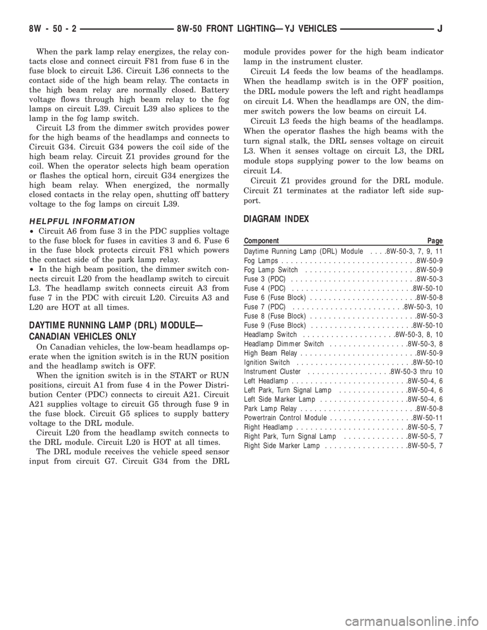
When the park lamp relay energizes, the relay con-
tacts close and connect circuit F81 from fuse 6 in the
fuse block to circuit L36. Circuit L36 connects to the
contact side of the high beam relay. The contacts in
the high beam relay are normally closed. Battery
voltage flows through high beam relay to the fog
lamps on circuit L39. Circuit L39 also splices to the
lamp in the fog lamp switch.
Circuit L3 from the dimmer switch provides power
for the high beams of the headlamps and connects to
Circuit G34. Circuit G34 powers the coil side of the
high beam relay. Circuit Z1 provides ground for the
coil. When the operator selects high beam operation
or flashes the optical horn, circuit G34 energizes the
high beam relay. When energized, the normally
closed contacts in the relay open, shutting off battery
voltage to the fog lamps on circuit L39.
HELPFUL INFORMATION
²Circuit A6 from fuse 3 in the PDC supplies voltage
to the fuse block for fuses in cavities 3 and 6. Fuse 6
in the fuse block protects circuit F81 which powers
the contact side of the park lamp relay.
²In the high beam position, the dimmer switch con-
nects circuit L20 from the headlamp switch to circuit
L3. The headlamp switch connects circuit A3 from
fuse 7 in the PDC with circuit L20. Circuits A3 and
L20 are HOT at all times.
DAYTIME RUNNING LAMP (DRL) MODULEÐ
CANADIAN VEHICLES ONLY
On Canadian vehicles, the low-beam headlamps op-
erate when the ignition switch is in the RUN position
and the headlamp switch is OFF.
When the ignition switch is in the START or RUN
positions, circuit A1 from fuse 4 in the Power Distri-
bution Center (PDC) connects to circuit A21. Circuit
A21 supplies voltage to circuit G5 through fuse 9 in
the fuse block. Circuit G5 splices to supply battery
voltage to the DRL module.
Circuit L20 from the headlamp switch connects to
the DRL module. Circuit L20 is HOT at all times.
The DRL module receives the vehicle speed sensor
input from circuit G7. Circuit G34 from the DRLmodule provides power for the high beam indicator
lamp in the instrument cluster.
Circuit L4 feeds the low beams of the headlamps.
When the headlamp switch is in the OFF position,
the DRL module powers the left and right headlamps
on circuit L4. When the headlamps are ON, the dim-
mer switch powers the low beams on circuit L4.
Circuit L3 feeds the high beams of the headlamps.
When the operator flashes the high beams with the
turn signal stalk, the DRL senses voltage on circuit
L3. When it senses voltage on circuit L3, the DRL
module stops supplying power to the low beams on
circuit L4.
Circuit Z1 provides ground for the DRL module.
Circuit Z1 terminates at the radiator left side sup-
port.
DIAGRAM INDEX
Component Page
Daytime Running Lamp (DRL) Module. . . .8W-50-3, 7, 9, 11
Fog Lamps.............................8W-50-9
Fog Lamp Switch........................8W-50-9
Fuse 3 (PDC)...........................8W-50-3
Fuse 4 (PDC)..........................8W-50-10
Fuse 6 (Fuse Block).......................8W-50-8
Fuse 7 (PDC)........................8W-50-3, 10
Fuse 8 (Fuse Block).......................8W-50-3
Fuse 9 (Fuse Block)......................8W-50-10
Headlamp Switch....................8W-50-3, 8, 10
Headlamp Dimmer Switch.................8W-50-3, 8
High Beam Relay.........................8W-50-9
Ignition Switch.........................8W-50-10
Instrument Cluster..................8W-50-3 thru 10
Left Headlamp.........................8W-50-4, 6
Left Park, Turn Signal Lamp...............8W-50-4, 6
Left Side Marker Lamp...................8W-50-4, 6
Park Lamp Relay.........................8W-50-8
Powertrain Control Module..................8W-50-11
Right Headlamp........................8W-50-5, 7
Right Park, Turn Signal Lamp..............8W-50-5, 7
Right Side Marker Lamp..................8W-50-5, 7
8W - 50 - 2 8W-50 FRONT LIGHTINGÐYJ VEHICLESJ
Page 2106 of 2198
REAR LIGHTING
TAIL LAMPS AND LICENSE PLATE LAMPS
Circuit A6 in the Power Distribution Center (PDC)
connects to a bus bar in the fuse block. The fuse
block bus bar powers circuit F33. Circuit F33 con-
nects to the headlamp switch. Fuse 3 in the PDC
protects circuit A3. Fuse 8 in the fuse block protects
circuit F33.
The headlamp switch has three positions: ON,
PARK (parking lamps) and OFF, plus a dimmer
switch. When the headlamp switch is in the PARK or
ON position, the switch connects circuit F33 to cir-
cuit L7. From the headlamp switch, circuit L7
branches to power the front parking lamps and rear
tail and license plate lamps. The lamps are case
grounded.
HELPFUL INFORMATION
²If the vehicle is equipped with factory installed fog
lamps, circuit L7 splices to feed the park lamp relay.
²Jumper harnesses connect the tail, stop, turn sig-
nal lamp to the body harness.
²Check fuse 3 in the PDC.
²Check fuse 8 in the fuse block.
²Circuit L7 also feeds the radio, if equipped.
STOP LAMPS AND CHMSL LAMPS
Circuit A6 from fuse 3 in the Power Distribution
Center (PDC) supplies voltage to the fuse block bus
bar. The bus bar powers circuit F32 through fuse 3 in
the fuse block. Circuit F32 connects to the stop lamp
switch.
When the operator depresses the brake pedal, the
stop lamp switch closes, and connects circuit F32 to
circuit L50. Circuit L50 connects to the CHMSL
lamps and turn signal/hazard flasher. Circuit Z1 pro-
vides ground for the CHMSL lamps. The turn signal/
hazard flasher supplies current to the L62 and L63
circuits. Circuit L62 powers the right stop lamp. Cir-
cuit L63 powers the left stop lamp. The stop lamps
are case grounded.
HELPFUL INFORMATION
²Circuits L50 and Z1 pass through contacts in the
rear door before reaching the CHMSL lamps.
²Check fuse 3 in the PDC.²Check fuse 3 in the fuse block.
²Check for continuity across the stop lamp switch
when it is closed.
²If the vehicle is equipped with anti-lock brakes,
circuit L50 connects to the ABS module.
BACK-UP LAMPS
In the START or RUN position, the ignition switch
connects circuit A1 from fuse 4 in the Power Distri-
bution Center (PDC) to circuit A21. Circuit A21 feeds
a bus bar in the fuse block that powers circuit G5
through fuse 9.
Circuit G5 splices to supply power to the back-up
lamp switch. On automatic transmission vehicles, the
back-up lamp switch is part of an assembly that in-
cludes the PARK/NEUTRAL position switch.
When the operator puts the transmission in Re-
verse, the back-up lamp switch connects circuit G5 to
circuit L1. Circuit L1 feeds the case grounded
back-up lamps.
HELPFUL INFORMATION
²Check fuse 4 in the PDC.
²Check fuse 9 in the fuse block.
²Check for continuity across the back-up lamp
switch when it is closed.
DIAGRAM INDEX
Component Page
ABS Control Module......................8W-51-3
Back-Up Lamps..........................8W-51-4
Back-Up Lamp Switch.....................8W-51-2
Center High Mounted Stop Lamps (CHMSL).......8W-51-3
Fuse 3 (Fuse Block).......................8W-51-2
Fuse 3 (PDC)...........................8W-51-2
Fuse 4 (PDC)...........................8W-51-2
Fuse 9 (Fuse Block).......................8W-51-2
Fuse 8 (Fuse Block).......................8W-51-2
Headlamp Switch.........................8W-51-2
Ignition Switch..........................8W-51-2
Powertrain Control Module..................8W-51-3
Stop Lamp Switch........................8W-51-3
Tail, Stop, and Turn Signal Lamps.............8W-51-4
J8W-51 REAR LIGHTINGÐYJ VEHICLES 8W - 51 - 1