1995 JEEP CHEROKEE tow bar
[x] Cancel search: tow barPage 341 of 2198

spring loaded to release when the key is released.
The maximum voltage drop between any two con-
nected terminals should not exceed 12.5 millivolts
per amp. For example: If a 10 amp load is drawn
through the switch, maximum voltage drop should be
10 x 0.0125 or 0.125 volt.
INSTALLATION/ADJUSTMENT
(1) Place the key lock switch in the ACCESSORY
position.
(2) Place the slider bar (in the ignition switch)
(Fig. 12) into the ACCESSORY detent position.
(3) Connect the wiring to the switch as follows: In-
stall the non-black (colored) connector first and then
the black (colored) connector to the ignition switch.
One connector will interlock the other connector.
(4) Slip the remote actuator rod into the access
hole on the switch (Fig. 12). Install the switch to the
steering column. Be careful not to move the slider
bar (on the switch) out of the ACCESSORY detent
position. Remove the ignition switch actuator rod se-
curing-tape from steering column.
(5) Install the two ignition switch-to-steering col-
umn screws finger tight.Do not tighten screws at
this time.
(6) Adjust ignition switch as follows:
(a) Non-tilt steering column: While holding key
lock switch in ACCESSORY position, gently slide
ignition switchup(towards steering wheel). This
will remove slack from switch. Tighten attaching
screws. Do not allow the ignition switch to move
from the ACCESSORY detent position.
(b) Tilt steering column: While holding the key
lock switch in the ACCESSORY position, gently
slide the ignition switchdown(away from steering
wheel) to remove slack from switch. Tighten at-
taching screws. Do not allow the ignition switch to
move from the ACCESSORY detent position.
Because the ignition switch and the headlamp dim-
mer switch share the same two mounting screws, oneof the screws must be removed from the ignition
switch. This must be doneafterthe ignition switch
has been adjusted andbeforethe dimmer switch
has been installed. Remove one screw.Do notre-
move the stud/nut.
(7) Install the headlamp dimmer switch as follows:
Slip switch into actuator rod and position over the ig-
IGNITION SWITCH CONTINUITY TESTS
Fig. 13 Ignition Switch Terminals/Circuits
8D - 30 IGNITION SYSTEMSJ
Page 484 of 2198
REAR WINDOW DEFOGGER
CONTENTS
page page
DIAGNOSIS............................. 1
GENERAL INFORMATION.................. 1SERVICE PROCEDURES................... 3
GENERAL INFORMATION
The electrically-heated rear window defogger is an
available option on XJ (Cherokee), and YJ (Wrangler)
models equipped with the hardtop roof option. Fol-
lowing are general descriptions of the major compo-
nents in the rear window defogger system. Refer to
Group 8W - Wiring Diagrams for complete circuit de-
scriptions and diagrams.
REAR WINDOW GLASS GRID
The heated rear window glass has two electrically-
conductive vertical bus bars and a series of horizon-
tal grid lines made of a silver-ceramic material,
which is baked on and bonded to the inside surface of
the glass. The grid lines and bus bars comprise a
parallel electrical circuit.
When the rear window defogger switch is placed in
the ON position, current is directed to the rear win-
dow grid lines through the bus bars. The grid lines
heat the rear window to clear the surface of fog or
snow. Circuit protection for the heated grid circuit is
provided by fuse 18 (XJ) or fuse 6 (YJ) in the fuse-
block module.
The grid lines and bus bars are highly resistant to
abrasion. However, it is possible for an open to occur
in an individual grid line resulting in no current flow
through the line. The grid lines can be damaged or
scraped off with sharp instruments. Care should be
taken in cleaning the glass or removing foreign ma-
terials, decals or stickers. Normal glass cleaning sol-
vents or hot water used with rags or toweling is
recommended.A repair kit is available to repair the grid lines and
bus bars, or to reinstall the heated glass pigtail
wires.
DEFOGGER SWITCH
The rear window defogger switch is mounted in the
instrument panel left of the steering column for XJ,
or right of the steering column for YJ. The switch cir-
cuit is protected by fuse 8 (XJ) or fuse 9 (YJ) in the
fuseblock module. Actuating the switch energizes the
relay and electronic timer. A light-emitting diode
(LED) in the switch (XJ), or a indicator lamp in the
switch (YJ), illuminates to indicate when the system
is turned on. The defogger switch can not be re-
paired. If faulty, the switch must be replaced.
DEFOGGER RELAY/TIMER
The defogger relay/timer is located in the relay cen-
ter on XJ models, or taped to the instrument panel
wiring harness behind the parking brake pedal in the
left cowl side area on YJ models. When the rear de-
fogger switch is actuated, the rear defogger relay is
energized. This causes current to flow through the
grid circuit for approximately 10 minutes, or until
the rear window defogger switch or ignition switch
are turned off.
DIAGNOSIS
SYSTEM TESTS
Electrically-heated rear window defogger operation
can be confirmed in the following manner:
(1) Turn the ignition switch to the ON position.
(2) Turn rear window defogger control switch ON.
(3) Monitor vehicle voltmeter. With the control
switch ON, a distinct needle deflection should be
noted.(4) The rear window defogger operation can be
checked by feeling the glass. A distinct difference in
temperature between the grid lines and adjacent
clear glass can be detected within 3 to 4 minutes of
operation.
(5) Using a DC voltmeter, contact terminal A (Fig.
1) (passenger side) with the negative lead, and termi-
JREAR WINDOW DEFOGGER 8N - 1
Page 485 of 2198
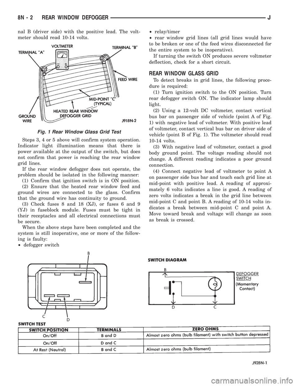
nal B (driver side) with the positive lead. The volt-
meter should read 10-14 volts.
Steps 3, 4 or 5 above will confirm system operation.
Indicator light illumination means that there is
power available at the output of the switch, but does
not confirm that power is reaching the rear window
grid lines.
If the rear window defogger does not operate, the
problem should be isolated in the following manner:
(1) Confirm that ignition switch is in ON position.
(2) Ensure that the heated rear window feed and
ground wires are connected to the glass. Confirm
that the ground wire has continuity to ground.
(3) Check fuses 8 and 18 (XJ), or fuses 6 and 9
(YJ) in fuseblock module. Fuses must be tight in
their receptacles and all electrical connections must
be secure.
When the above steps have been completed and the
system is still inoperative, one or more of the follow-
ing is faulty:
²defogger switch²relay/timer
²rear window grid lines (all grid lines would have
to be broken or one of the feed wires disconnected for
the entire system to be inoperative).
If turning the switch ON produces severe voltmeter
deflection, check for a short circuit.
REAR WINDOW GLASS GRID
To detect breaks in grid lines, the following proce-
dure is required:
(1) Turn ignition switch to the ON position. Turn
rear defogger switch ON. The indicator lamp should
light.
(2) Using a 12-volt DC voltmeter, contact vertical
bus bar on passenger side of vehicle (point A of Fig.
1) with negative lead of voltmeter. With positive lead
of voltmeter, contact vertical bus bar on driver side of
vehicle (point B of Fig. 1). The voltmeter should read
10-14 volts.
(3) With negative lead of voltmeter, contact a good
body ground point. The voltage reading should not
change. A different reading indicates a poor ground
connection.
(4) Connect negative lead of voltmeter to point A
on passenger side bus bar and touch each grid line at
mid-point with positive lead. A reading of approxi-
mately 6 volts indicates a line is good. A reading of
zero volts indicates a break in the grid line between
mid-point C and point B. A reading of 10-14 volts in-
dicates a break between mid-point C and point A.
Move toward break and voltage will change as soon
as break is crossed.
Fig. 1 Rear Window Glass Grid Test
8N - 2 REAR WINDOW DEFOGGERJ
Page 670 of 2198
REAR LIGHTING
TAIL LAMPS AND REAR LICENSE PLATE LAMPS
Circuit A3 from fuse 5 in the Power Distribution
Center (PDC) connects to a bus bar in the fuse block
which feeds circuit L7. Fuse 15 in the fuse block pro-
tects circuit L7.
The headlamp switch has three positions: ON,
PARK (parking lamps) and OFF, plus a dimmer
switch. When the headlamp switch is in the PARK or
ON position, the switch connects circuit L7 to circuit
L90. From the headlamp switch, circuit L90 branches
to power the front parking lamps and rear tail
lamps, side marker lamps, and rear license plate
lamps.
GROUND CIRCUIT
Circuit Z1 provides a ground for the parking lamps,
tail lamps, and rear license plate lamps.
HELPFUL INFORMATION
²If the vehicle is equipped with factory installed
trailer tow, circuit L90 splices to the trailer tow har-
ness.
²Check fuse 5 in PDC.
²Check fuse 15 in the fuse block.
²When the headlamp switch is in the PARK or ON
position, circuit L7 also connects to circuit E2. Cir-
cuit E2 continues through fuse 19 in the fuse block.
Circuit E2 powers the illumination lamps.
STOP LAMPS AND CHMSL LAMPS
Circuit L9 from fuse 4 in the Power Distribution
Center (PDC) connects to the stop lamp switch.
When the operator depresses the brake pedal, the
stop lamp switch closes and connects circuit L9 to
circuit L50. Circuit L50 connects to the stop lamps
and Center High Mounted Stop Lamps (CHMSL).
Circuit Z1 provides a ground for the stop lamps and
CHMSL lamps.
HELPFUL INFORMATION
²Check fuse 4 in the PDC.
²Check for continuity across the stop lamp switch
when it is closed.
BACK-UP LAMPS
In the START or RUN position, the ignition switch
connects circuit A1 from fuse 6 in the Power Distri-
bution Center (PDC) to circuit A21. Circuit A21 feeds
a bus bar in the PDC that powers circuit F12
through fuse 11.
Circuit F20 supplies power to the back-up lamp
switch. On automatic transmission equipped vehicles,
the back-up lamp switch is part of an assembly that
includes the PARK/NEUTRAL position switch. When
the operator puts the transmission in REVERSE, the
back-up lamp switch connects circuit F20 to circuit
L10. Circuit L10 feeds the back-up lamps. Circuit Z1
provides ground for the back-up lamps.
HELPFUL INFORMATION
²Check fuses 6 and 11 in the PDC.
²Check for continuity across the back-up lamp
switch when it is closed.
DIAGRAM INDEX
Component Page
Back-Up Lamps........................8W-51-4, 5
Back-Up Lamp Switch.....................8W-51-2
Center High Mounted Stop Lamps (CHMSL).......8W-51-3
Fuse 15 (Fuse Block)......................8W-51-2
Fuse 4 (PDC)...........................8W-51-3
Fuse 6 (PDC)...........................8W-51-2
Fuse 7 (PDC)...........................8W-51-2
Fuse 11 (PDC)..........................8W-51-2
Headlamp Switch.........................8W-51-2
Ignition Switch..........................8W-51-2
License Plate Lamp.......................8W-51-3
Park/Neutral Position Switch.................8W-51-2
Side Marker Lamps.....................8W-51-4, 5
Stop Lamp Switch........................8W-51-3
Tail/Stop Lamps........................8W-51-4, 5
Turn Signal Lamps......................8W-51-4, 5
J8W-51 REAR LIGHTINGÐXJ VEHICLES 8W - 51 - 1
Page 1095 of 2198
CONNECTING ROD BEARING CLEARANCE
Engine connecting rod bearing clearances can be
determined by use of Plastigage, or equivalent. The
following is the recommended procedures for the use
of Plastigage:
(1) Remove oil film from surface to be checked.
Plastigage is soluble in oil.
(2) Place a piece of Plastigage across the entire width
of the bearing cap shell (Fig. 2). Position the Plastigage
approximately 6.35 mm (1/4 inch) off center and away
from the oil holes. In addition, suspect areas can be
checked by placing the Plastigage in the suspect area.
(3) The crankshaft must be turned until the connect-
ing rod to be checked starts moving toward the top of
the engine. Only then should the rod cap with Plasti-
gage in place be assembled. Tighten the rod cap nut to
45 Nzm (33 ft. lbs.) torque.DO NOT rotate the crank-
shaft or the Plastigage may be smeared, giving in-
accurate results.
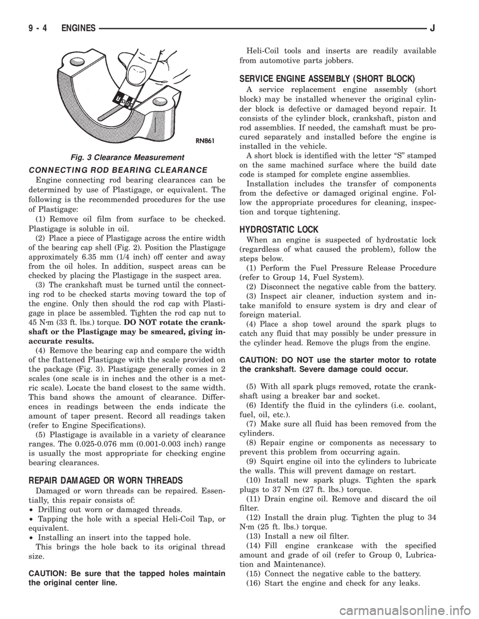
(4) Remove the bearing cap and compare the width
of the flattened Plastigage with the scale provided on
the package (Fig. 3). Plastigage generally comes in 2
scales (one scale is in inches and the other is a met-
ric scale). Locate the band closest to the same width.
This band shows the amount of clearance. Differ-
ences in readings between the ends indicate the
amount of taper present. Record all readings taken
(refer to Engine Specifications).
(5) Plastigage is available in a variety of clearance
ranges. The 0.025-0.076 mm (0.001-0.003 inch) range
is usually the most appropriate for checking engine
bearing clearances.
REPAIR DAMAGED OR WORN THREADS
Damaged or worn threads can be repaired. Essen-
tially, this repair consists of:
²Drilling out worn or damaged threads.
²Tapping the hole with a special Heli-Coil Tap, or
equivalent.
²Installing an insert into the tapped hole.
This brings the hole back to its original thread
size.
CAUTION: Be sure that the tapped holes maintain
the original center line.Heli-Coil tools and inserts are readily available
from automotive parts jobbers.
SERVICE ENGINE ASSEMBLY (SHORT BLOCK)
A service replacement engine assembly (short
block) may be installed whenever the original cylin-
der block is defective or damaged beyond repair. It
consists of the cylinder block, crankshaft, piston and
rod assemblies. If needed, the camshaft must be pro-
cured separately and installed before the engine is
installed in the vehicle.
A short block is identified with the letter ``S'' stamped
on the same machined surface where the build date
code is stamped for complete engine assemblies.
Installation includes the transfer of components
from the defective or damaged original engine. Fol-
low the appropriate procedures for cleaning, inspec-
tion and torque tightening.
HYDROSTATIC LOCK
When an engine is suspected of hydrostatic lock
(regardless of what caused the problem), follow the
steps below.
(1) Perform the Fuel Pressure Release Procedure
(refer to Group 14, Fuel System).
(2) Disconnect the negative cable from the battery.
(3) Inspect air cleaner, induction system and in-
take manifold to ensure system is dry and clear of
foreign material.
(4) Place a shop towel around the spark plugs to
catch any fluid that may possibly be under pressure in
the cylinder head. Remove the plugs from the engine.
CAUTION: DO NOT use the starter motor to rotate
the crankshaft. Severe damage could occur.
(5) With all spark plugs removed, rotate the crank-
shaft using a breaker bar and socket.
(6) Identify the fluid in the cylinders (i.e. coolant,
fuel, oil, etc.).
(7) Make sure all fluid has been removed from the
cylinders.
(8) Repair engine or components as necessary to
prevent this problem from occurring again.
(9) Squirt engine oil into the cylinders to lubricate
the walls. This will prevent damage on restart.
(10) Install new spark plugs. Tighten the spark
plugs to 37 Nzm (27 ft. lbs.) torque.
(11) Drain engine oil. Remove and discard the oil
filter.
(12) Install the drain plug. Tighten the plug to 34
Nzm (25 ft. lbs.) torque.
(13) Install a new oil filter.
(14) Fill engine crankcase with the specified
amount and grade of oil (refer to Group 0, Lubrica-
tion and Maintenance).
(15) Connect the negative cable to the battery.
(16) Start the engine and check for any leaks.
Fig. 3 Clearance Measurement
9 - 4 ENGINESJ
Page 1863 of 2198
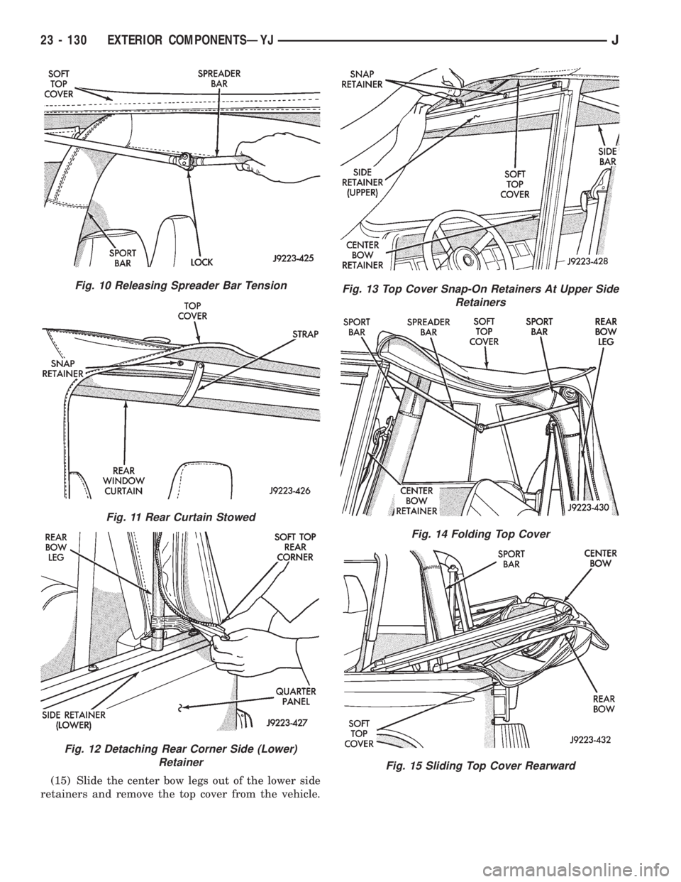
(15) Slide the center bow legs out of the lower side
retainers and remove the top cover from the vehicle.
Fig. 10 Releasing Spreader Bar Tension
Fig. 11 Rear Curtain Stowed
Fig. 12 Detaching Rear Corner Side (Lower)
Retainer
Fig. 13 Top Cover Snap-On Retainers At Upper Side
Retainers
Fig. 14 Folding Top Cover
Fig. 15 Sliding Top Cover Rearward
23 - 130 EXTERIOR COMPONENTSÐYJJ
Page 1864 of 2198
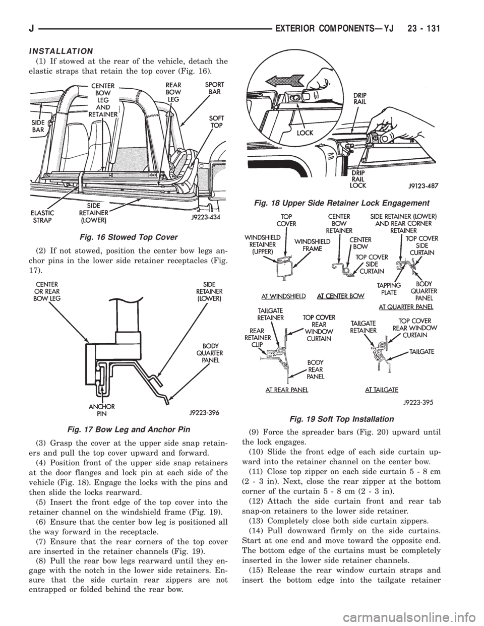
INSTALLATION
(1) If stowed at the rear of the vehicle, detach the
elastic straps that retain the top cover (Fig. 16).
(2) If not stowed, position the center bow legs an-
chor pins in the lower side retainer receptacles (Fig.
17).
(3) Grasp the cover at the upper side snap retain-
ers and pull the top cover upward and forward.
(4) Position front of the upper side snap retainers
at the door flanges and lock pin at each side of the
vehicle (Fig. 18). Engage the locks with the pins and
then slide the locks rearward.
(5) Insert the front edge of the top cover into the
retainer channel on the windshield frame (Fig. 19).
(6) Ensure that the center bow leg is positioned all
the way forward in the receptacle.
(7) Ensure that the rear corners of the top cover
are inserted in the retainer channels (Fig. 19).
(8) Pull the rear bow legs rearward until they en-
gage with the notch in the lower side retainers. En-
sure that the side curtain rear zippers are not
entrapped or folded behind the rear bow.(9) Force the spreader bars (Fig. 20) upward until
the lock engages.
(10) Slide the front edge of each side curtain up-
ward into the retainer channel on the center bow.
(11) Close top zipper on each side curtain5-8cm
(2 - 3 in). Next, close the rear zipper at the bottom
corner of the curtain5-8cm(2-3in).
(12) Attach the side curtain front and rear tab
snap-on retainers to the lower side retainer.
(13) Completely close both side curtain zippers.
(14) Pull downward firmly on the side curtains.
Start at one end and move toward the opposite end.
The bottom edge of the curtains must be completely
inserted in the lower side retainer channels.
(15) Release the rear window curtain straps and
insert the bottom edge into the tailgate retainer
Fig. 16 Stowed Top Cover
Fig. 17 Bow Leg and Anchor Pin
Fig. 18 Upper Side Retainer Lock Engagement
Fig. 19 Soft Top Installation
JEXTERIOR COMPONENTSÐYJ 23 - 131
Page 1987 of 2198
SHUTDOWN (ASD) RELAY, AUTOMATIC;
FUEL SYSTEM.......................14-59
SHUTDOWN (ASD) RELAY, AUTOMATIC;
IGNITION SYSTEMS..............8D-17,8D-1
SHUTDOWN (ASD) RELAY TEST,
AUTOMATIC.........................8D-6
SHUTDOWN (ASD) RELAY TESTING,
AUTOMATIC.........................14-46
SHUTDOWN (ASD) RELAYÐPCM
OUTPUT, AUTO......................14-26
SHUTDOWN (ASD) SENSEÐPCM INPUT,
AUTOMATIC.........................14-21
SIDE COVER REPLACEMENT, PITMAN
SHAFT.............................19-28
SIDE MARKER LAMP BULB
REPLACEMENTÐXJ..................8L-10
SIDE MARKER LAMP BULB
REPLACEMENTÐYJ..................8L-25
SIDE MOLDING/CLADDINGÐXJ, BODY . . . 23-20
SIDE MOLDINGÐXJ, WINDSHIELD......23-86
SIDE STEP MOLDINGÐYJ, BODY.......23-115
SIDE TRIM PANELÐXJ, FRONT INNER
SCUFF PLATE/COWL..................23-86
SIGNAL INDICATOR LAMPS, TURN;
INSTRUMENT CLUSTER (XJ).........8W-40-2
SIGNAL INDICATOR LAMPS, TURN;
INSTRUMENT CLUSTER (XJ-RHD).....8W-40-2
SIGNAL LAMP BULB REPLACEMENTÐ
XJ, FRONT PARK/TURN.................8L-9
SIGNAL LAMP BULB REPLACEMENTÐ
YJ, FRONT PARK/TURN................8L-25
SIGNAL RELAY, TURN; TURN SIGNALS
(XJ-RHD)..........................8W-52-1
SIGNAL SYSTEM - YJ, TURN............8J-3
SIGNAL SYSTEM, TURN................8J-1
SIGNAL, TACHOMETER; FUEL/IGNITION
(XJ).............................8W-30-5
SIGNAL, TACHOMETER; FUEL/IGNITION
(YJ).............................8W-30-5
SIGNAL, TACHOMETER; FUEL/IGNITION
(XJ-RHD).........................8W-30-4
SIGNAL/HAZARD WARNING SWITCH
REMOVE/INSTALL - YJ, TURN............8J-5
SIGNAL/HAZARD WARNING SYSTEM -
XJ, TURN............................8J-3
SIGNALS, TURN; TURN SIGNALS (YJ) . . 8W-52-1
SIGNALS, WHEEL/TIRE SIZE AND INPUT....5-3
SIGNAL/TAIL LAMP BULB
REPLACEMENTÐXJ, BACK-UP/REAR
TURN..............................8L-12
SIGNAL/TAIL LAMP BULB
REPLACEMENTÐYJ, BACK-UP/REAR
TURN..............................8L-28
SINGLE CARDAN.....................16-10
SIZE AND INPUT SIGNALS, WHEEL/TIRE....5-3
SKID PLATE, FRONT...................13-1
SKID PLATE, FUEL TANK...........13-15,13-3
SKID PLATE, TRANSFER CASE......13-15,13-3
SLIP DIFFERENTIAL, LIMITED............3-10
SNAP, DRIVELINE; FRONT SUSPENSION
AND AXLE...........................2-19
SNAP, DRIVELINE; REAR SUSPENSION
AND AXLES..........................3-10
SNAP RING CHARTÐAX 15 MANUAL
TRANSMISSION, SELECTIVE...........21-334
SNAP RING/THRUST WASHER/THRUST
PLATE SPECIFICATIONS, 30RH/32RH....21-335
SOFT TOP DOORÐYJ, HALF-METAL.....23-134
SOFT TOP SERVICE INFORMATIONÐYJ . . 23-127
SOFT TOP SERVICEÐYJ..............23-129
SOLENOID AND RELAY, TORQUE
CONVERTER CLUTCH (TCC);
FUEL/IGNITION (XJ)................8W-30-4
SOLENOID AND RELAY, TORQUE
CONVERTER CLUTCH (TCC);
TRANSMISSION CONTROLS (YJ)......8W-31-1
SOLENOID AND RELAYÐ2.5L ENGINE
ONLY, TORQUE CONVERTER CLUTCH
(TCC); TRANSMISSION CONTROLS
(XJ)
.............................8W-31-1
SOLENOID TESTING SPECIFICATIONS,
2.5L STARTER
.......................8A-23
SOLENOID TESTING SPECIFICATIONS,
4.0L STARTER
.......................8A-23
SOLENOIDS, TRANSMISSION VALVE
BODY
.............................21-184
SOLVENTS, BRAKE FLUID/LUBRICANTS/
CLEANING
............................5-2SOUND BAR REMOVE/INSTALL - XJ.......8F-8
SOUND BAR REMOVE/INSTALL - YJ......8F-10
SOUND BARÐXJ....................23-94
SPACER BLOCKSÐTWO-DOOR
VEHICLES, FRONT DOOR..............23-53
SPARE TIRE/WHEEL HOLDDOWN AND
FLOOR BRACKETSÐXJ................23-98
SPARE/WHEEL TIRE CARRIERÐYJ,
EXTERNAL.........................23-133
SPARK PLUG CABLE RESISTANCE.......8D-14
SPARK PLUG SECONDARY CABLES . 8D-14,8D-24
SPARK PLUGS; IGNITION SYSTEMS.....8D-12,
8D-23,8D-32
SPARK PLUGS; LUBRICATION AND
MAINTENANCE.......................0-20
SPEAKERS; AUDIO SYSTEMS........8F-1,8F-2
SPEAKERS; RADIO (XJ).............8W-47-1
SPEAKERS; RADIO (XJ-RHD).........8W-47-1
SPEAKERS; RADIO (YJ).............8W-47-1
SPEAKERS REMOVE/INSTALL - XJ........8F-6
SPEAKERS REMOVE/INSTALL - YJ........8F-9
SPECIFICATION NOTATIONS..........Intro.-11
SPECIFICATIONS; BATTERY/STARTER/
GENERATOR SERVICE..................8B-8
SPECIFICATIONS; BATTERY/STARTING/
CHARGING SYSTEMS DIAGNOSTICS.....8A-23
SPECIFICATIONS; BRAKES..............5-70
SPECIFICATIONS; COOLING SYSTEM......7-45
SPECIFICATIONS; ENGINES...........9-52,9-93
SPECIFICATIONS; FUEL SYSTEM........14-67
SPECIFICATIONS; HORNS...............8G-5
SPECIFICATIONS; IGNITION SYSTEMS....8D-32
SPECIFICATIONS; INSTRUMENT PANEL
AND GAUGESÐXJ..............8E-23,8E-43
SPECIFICATIONS; WHEELS AND TIRES....22-12
SPECIFICATIONS, 2.5L STARTER AND
SOLENOID TESTING..................8A-23
SPECIFICATIONS, 2.5L STARTING
SYSTEM COLD CRANKING.............8A-23
SPECIFICATIONS, 30RH/32RH GENERAL . 21-335
SPECIFICATIONS, 30RH/32RH PRESSURE
TEST.............................21-336
SPECIFICATIONS, 30RH/32RH TORQUE . . 21-336
SPECIFICATIONS, 4.0L STARTER AND
SOLENOID TESTING..................8A-23
SPECIFICATIONS, 4.0L STARTING
SYSTEM COLD CRANKING.............8A-23
SPECIFICATIONS, AW-4 GENERAL......21-337
SPECIFICATIONS, AW-4 TORQUE.......21-344
SPECIFICATIONS, AXLE; FRONT
SUSPENSION AND AXLE................2-49
SPECIFICATIONS, AXLE; REAR
SUSPENSION AND AXLES...............3-51
SPECIFICATIONS, BATTERY; BATTERY/
STARTER/GENERATOR SERVICE..........8B-8
SPECIFICATIONS, BATTERY; BATTERY/
STARTING/CHARGING SYSTEMS
DIAGNOSTICS.......................8A-23
SPECIFICATIONS, BELT TENSION.........7-38
SPECIFICATIONS, BODY LUBRICANT......0-33
SPECIFICATIONS, BRAKE TORQUE........5-70
SPECIFICATIONS, CHARGING SYSTEM....8A-23
SPECIFICATIONS (CONT.), ENGINE....9-53,9-54,
9-94,9-95
SPECIFICATIONS, ENGINE...........9-52,9-93
SPECIFICATIONS, GENERATOR...........8B-8
SPECIFICATIONS, LUBRICANT; FRONT
SUSPENSION AND AXLE................2-22
SPECIFICATIONS, LUBRICANT; REAR
SUSPENSION AND AXLES...........3-13,3-31
SPECIFICATIONS, MANUAL STEERING
GEAR..............................19-46
SPECIFICATIONS, MEASUREMENT AND
TORQUE.........................Intro.-11
SPECIFICATIONS, NP231/NP242 TORQUE . 21-344
SPECIFICATIONS, OUTPUT VOLTAGE.....8A-23
SPECIFICATIONS, POWER STEERING
GEAR..............................19-36
SPECIFICATIONS, PUMP OPERATING......19-3
SPECIFICATIONS, RUNOUT..............16-4
SPECIFICATIONS, STARTER.............8B-8
SPECIFICATIONS, STARTING SYSTEM
....8A-23
SPECIFICATIONS, TORQUE; CLUTCH
......6-17
SPECIFICATIONS, TORQUE; ENGINES
. . 9-54,9-95
SPECIFICATIONS, TORQUE; EXHAUST
SYSTEM AND INTAKE MANIFOLD
........11-10
SPECIFICATIONS, TORQUE; FRONT
SUSPENSION AND AXLE
................2-49SPECIFICATIONS, TORQUE; HEATING
AND AIR CONDITIONING...............24-37
SPECIFICATIONS, TORQUE;
INTRODUCTION............Intro.-11,Intro.-12
SPECIFICATIONS, TORQUE; PROPELLER
SHAFTS............................16-15
SPECIFICATIONS, TORQUE; REAR
SUSPENSION AND AXLES...............3-51
SPECIFICATIONS, TORQUE; STEERING....19-78
SPECIFICATIONS, TRAILER TOWING....Intro.-5,
Intro.-9
SPECIFICATIONS, TRANSMISSION/
TRANSFER CASE....................21-333
SPECIFICATIONSÐACCESSORIES,
TORQUE...........................23-162
SPECIFICATIONSÐMANUAL
TRANSMISSION, TORQUE.............21-333
SPECIFICATIONSÐXJ VEHICLES,
ALIGNMENT..........................2-10
SPECIFICATIONSÐXJ VEHICLES,
TORQUE...........................23-161
SPECIFICATIONSÐYJ VEHICLES,
ALIGNMENT..........................2-10
SPEED CONTROL DIAGNOSTIC TROUBLE
CODE...............................8H-5
SPEED CONTROL SERVO...........8H-1,8H-6
SPEED CONTROL SERVO REMOVE/
INSTALL............................8H-9
SPEED CONTROL SWITCH..........8H-1,8H-6
SPEED CONTROL SWITCH REMOVE/
INSTALL............................8H-9
SPEED CONTROL, VEHICLE; VEHICLE
SPEED CONTROL (XJ)................8W-33-1
SPEED CONTROL, VEHICLE; VEHICLE
SPEED CONTROL (XJ-RHD)..........8W-33-1
SPEED CONTROLÐPCM INPUT.........14-25
SPEED CONTROLÐPCM OUTPUT........14-29
SPEED KNOCK, LOW; FRONT
SUSPENSION AND AXLE................2-19
SPEED KNOCK, LOW; REAR
SUSPENSION AND AXLES...............3-10
SPEED SENSOR.....................21-192
SPEED SENSOR AIR GAP...............5-37
SPEED SENSOR OPERATION, WHEEL......5-37
SPEED SENSOR, PUMP MOTOR;
ANTI-LOCK BRAKES (XJ)............8W-32-2
SPEED SENSOR, PUMP MOTOR;
ANTI-LOCK BRAKES (XJ-RHD)........8W-32-2
SPEED SENSOR, PUMP MOTOR;
ANTI-LOCK BRAKES (YJ)............8W-32-1
SPEED SENSOR ROTORÐ
SPEEDOMETER DRIVE GEAR..........21-193
SPEED SENSOR TEST, VEHICLE.........14-48
SPEED SENSOR, VEHICLE; FUEL
SYSTEM............................14-66
SPEED SENSOR, VEHICLE; FUEL/
IGNITION (XJ).....................8W-30-2
SPEED SENSOR, VEHICLE; FUEL/
IGNITION (YJ).....................8W-30-3
SPEED SENSOR, VEHICLE; VEHICLE
SPEED CONTROL SYSTEM..........8H-1,8H-5
SPEED SENSOR, VEHICLE; FUEL/
IGNITION (XJ-RHD)................8W-30-2
SPEED SENSORÐPCM INPUT, VEHICLE . . 14-25
SPEED SENSORS, WHEEL; ANTI-LOCK
BRAKES (XJ)......................8W-32-1
SPEED SENSORS, WHEEL; ANTI-LOCK
BRAKES (XJ-RHD).................8W-32-1
SPEED SENSORS, WHEEL; ANTI-LOCK
BRAKES (YJ)
......................8W-32-1
SPEED SENSORS, WHEEL; BRAKES
.......5-34
SPEEDOMETER; INSTRUMENT CLUSTER
(XJ)
.............................8W-40-2
SPEEDOMETER; INSTRUMENT CLUSTER
(XJ-RHD)
.........................8W-40-1
SPEEDOMETER CABLE
.................0-33
SPEEDOMETER SERVICE
. . 21-109,21-287,21-309
SPLASH APRONSÐYJ, FENDER
........23-115
SPLASH LINERSÐYJ, WHEELHOUSE
....23-115
SPLASH SHIELD, GENERATOR
..........13-13
SPLASH SHIELDÐXJ VEHICLES, FUEL
FILLER HOSE
.........................13-4
SPLASH SHIELDSÐYJ, FENDER INNER
. . 23-116
SPLICE INDEX; SPLICE INFORMATION
(XJ)
.............................8W-70-1
SPLICE INDEX; SPLICE INFORMATION
(XJ-RHD)
.........................8W-70-1
26 INDEXJ
Description Group-Page Description Group-Page Description Group-Page