1995 JEEP CHEROKEE Fuse block
[x] Cancel search: Fuse blockPage 965 of 2198
Ground for the window motor is supplied on the
Q12 circuit back to the right rear door switch. Circu-
ity internal to the switch then passes the ground to
circuit Q28. Circuit Q28 goes from the right rear door
switch to the master switch. A bus bar, internal to
the switch, connects the Q28 circuit to the Z1 circuit.
For window UP operation the circuits are reversed.
Circuits Q28 and Q12 are the feeds, and circuits Q22,
Q33 and Q18 are the grounds.
If the switch is being operated from the RIGHT
REAR door, and the operator is requesting window
DOWN operation, power is supplied on the Q1 circuit
from the driver's master switch circuit through the
switch to the Q22 circuit.
Ground for the motor is supplied on the Q12 circuit
through the switch and back to the master switch on
circuit Q28. A bus bar, internal to the switch, con-
nects the Q28 circuit to the Z1 circuit.For window UP operation, the circuits are reversed.
Circuit Q12 is the power and circuits Q22 and Q18
are the ground.
HELPFUL INFORMATION
Refer to the appropriate group of the Service Man-
ual for test procedures.
DIAGRAM INDEX
Component Page
Fuse 6 (PDC)...........................8W-60-3
Fuse 12 (Fuse Block)......................8W-60-3
Ignition Switch..........................8W-60-3
Power Window Door Switches................8W-60-4
Power Window Master Switch................8W-60-3
Power Window Motors.....................8W-60-4
8W - 60 - 2 8W-60 POWER WINDOWSÐXJ-RHDJ
Page 968 of 2198
POWER DOOR LOCKS
POWER DOOR LOCKS
Two relays provide power for the power door lock
motors. The Unlock relay provides power for the un-
lock circuits while the Lock relay powers the lock cir-
cuits. Either power door lock switch can operate the
Unlock and Lock relays.
LOCK RELAY
Circuit A7 from fuse 3 in the Power Distribution
Center (PDC) powers circuits P37 and P38 through
fuse 6 in the fuse block. When either power door lock
switch is put in the LOCK position, the switch con-
nects circuit P38 to circuit P35. Circuit P35 supplies
power to the coil side of the lock relay, causing the
relay contacts to close. Circuit Z1 provides ground for
the coil side of the lock relay.
When the lock relay contacts close, they connect
battery voltage from circuit P37 to circuit P2. Circuit
P2 then supplies battery voltage to the power door
lock motors to LOCK the doors.
When the power doors LOCK, ground for the mo-
tors is on circuit P34 through the normally closed
contacts in the door unlock relay to ground on circuit
Z1.
UNLOCK RELAY
Circuit A7 from fuse 3 in the Power Distribution
Center (PDC) powers circuits P37 and P38 through
fuse 6 in the fuse block. When either power door lock
switch is put in the UNLOCK position, the switch
connects circuit P38 to circuit P36. Circuit P36 sup-
plies power to the coil side of the unlock relay, caus-
ing the relay contacts to close. Circuit Z1 provides
ground for the coil side of the unlock relay.
When the unlock relay contacts close, they connect
battery voltage from circuit P37 to circuit P34. Cir-
cuit P34 then supplies battery voltage to the power
door lock motors to UNLOCK the doors.
When the power doors UNLOCK, ground for the
motors is on circuit P2 through the normally closed
contacts in the door lock relay to ground on circuit
Z1.
DIAGRAM INDEX
Component Page
Fuse 3 (PDC)...........................8W-61-2
Fuse 6 (Fuse Block).......................8W-61-2
Liftgate Lock Motor.......................8W-61-3
Power Door Lock Motors...................8W-61-3
Power Door Lock Relay....................8W-61-2
Power Door Lock Switches..................8W-61-2
Power Door Unlock Relay...................8W-61-2
J8W-61 POWER DOOR LOCKSÐXJ-RHD 8W - 61 - 1
Page 972 of 2198
POWER MIRRORS
INDEX
page page
Diagram Index............................ 1
Heater Elements........................... 1Power Mirrors............................. 1
POWER MIRRORS
Four switches operates the left and right power
mirrors. One switch selects right or left mirror. Each
mirror has two motors; a LEFT/RIGHT motor and a
UP/DOWN motor. The motors switch polarity to al-
low mirror adjustment.
Circuit A7 from fuse 13 in the Power Distribution
Center (PDC) supplies battery voltage to fuse 8 in
the fuse block. Fuse 8 supplies voltage to circuit P60.
Circuit P60 powers the power mirror switch. Circuit
Z1 connects to the power mirror switch and supplies
ground for the power mirror system.
RIGHT POWER MIRROR OPERATION
In the right position, the power mirror switch sup-
plies power to the right mirror LEFT/RIGHT motor
on circuit P79 when a rightward adjustment is made.
Circuit P77 provides the ground path the for right-
ward adjustments.
When the operator makes leftward adjustment, po-
larity reverses. For leftward adjustments, the switch
supplies battery voltage to the right mirror LEFT/
RIGHT motor on circuit P77. Circuit P79 supplies
ground for leftward adjustments.
During upward adjustments, the switch supplies
voltage to the right mirror UP/DOWN motor on cir-
cuit P79. Circuit P80 supplies ground during upward
adjustments.
For downward adjustments, the polarity is re-
versed, the switch powers the right mirror UP/
DOWN motor on circuit P80. Circuit P79 supplies the
ground path.
LEFT POWER MIRROR OPERATION
In the left position, the power mirror switch sup-
plies power to the left mirror LEFT/RIGHT motor on
circuit P79 when a rightward adjustment is made.
Circuit P81 provides the ground path the for right-
ward adjustments.
When the operator makes leftward adjustment, po-
larity reverses. For leftward adjustments, the switch
supplies battery voltage the left mirror LEFT/RIGHT
motor on circuit P81. Circuit P79 supplies ground for
leftward adjustments.
During upward adjustments, the switch supplies
voltage to the left mirror UP/DOWN motor on circuit
P79. Circuit P78 supplies ground during upward ad-
justments.For downward adjustments, the polarity is re-
versed, the switch powers the left mirror UP/DOWN
motor on circuit P78. Circuit P79 supplies the ground
path.
HELPFUL INFORMATION
²Check fuse 3 in the PDC and fuse 8 in the fuse
block in the PDC
HEATER ELEMENTS
The heated rear window relay powers the heater
elements in power mirrors. When the relay energizes,
it supplies power to the heater elements on circuit
C15. Circuit Z1 provides ground for the power mirror
heater elements.
HELPFUL INFORMATION
²Circuit F82 from fuse 2 in the fuse block powers
circuit C15 when the heated rear window relay ener-
gizes.
²Circuit A4 from fuse 7 in the Power Distribution
Center (PDC) supplies battery voltage to the fuse
block for fuse 2 and circuit F85.
²Check fuse 2 in the fuse block.
²Check fuse 7 in the PDC.
DIAGRAM INDEX
Component Page
Fuse 1 (Fuse Block).......................8W-63-2
Fuse 3 (PDC)...........................8W-63-2
Power Seat............................8W-63-2
Power Seat Switch.......................8W-63-2
Fuse 2 (Fuse Block).......................8W-62-3
Fuse 3 (PDC)...........................8W-62-2
Fuse 7 (Fuse Block).......................8W-62-2
Fuse 7 (PDC)...........................8W-62-3
Fuse 8 (Fuse Block).......................8W-62-2
Fuse 16 (PDC)..........................8W-62-2
Heated Rear Window Relay..................8W-62-3
Power Mirrors..........................8W-62-2
Power Mirror Heater Elements................8W-62-3
Power Mirror Switch......................8W-62-2
J8W-62 POWER MIRRORSÐXJ-RHD 8W - 62 - 1
Page 976 of 2198
POWER SEAT
POWER SEAT
Battery voltage for the power seat system is sup-
plied by circuit A11 from fuse 1 in the fuse block. Cir-
cuit A11 is HOT at all times and supplies battery
voltage to the power seat switch.
A BUS bar internal to the power seat switch con-
nects the power from circuit A11 to the switches.
Grounding for the seat system is supplied on circuit
Z1.
The motors located under the seat are protected by
circuit breakers wired in with the motors. Each mo-
tor has its own circuit breaker.
When the operator selects the FRONT VERTICAL
UP function, power is passed on the A11 circuit
through the closed contacts in the switch to the S5
circuit. The S5 circuit connects to the motor. Ground
is provided on the S6 circuit back to the switch. A
ground BUS bar internal to the switch then connects
to the Z1 circuit.
For FRONT VERTICAL DOWN function the cir-
cuits are reversed. S6 is the feed and S5 is the
ground.
When the operator selects the SEAT FORWARD
function, power is passed on the A11 circuit through
the closed contacts in the switch to the S3 circuit.
The S3 circuit connects to the motor. Ground is pro-
vided on the S4 circuit back to the switch. A ground
BUS bar internal to the switch then connects to the
Z1 circuit.
For SEAT REARWARD function the circuits are re-
versed. S4 is the feed and S3 is the ground.When the operator selects the REAR VERTICAL
UP function, power is passed on the A11 circuit
through the closed contacts in the switch to the S1
circuit. The S1 circuit connects to the motor. Ground
is provided on the S2 circuit back to the switch. A
ground BUS bar internal to the switch then connects
to the Z1 circuit.
For REAR VERTICAL DOWN function the circuits
are reversed. S2 is the feed and S1 is the ground.
When the operator selects the SEAT UP function
power is passed on the A11 circuit through the closed
contacts in the switch to the S1 and S5 circuits. The
S1 circuit connects to the rear UP/DOWN motor, and
S5 connects to the front UP/DOWN motor. Ground is
provided on the S2 and S6 circuits back to the
switch. A ground BUS bar internal to the switch then
connects to the Z1 circuit.
For SEAT DOWN function the circuits are re-
versed. S2 and S6 circuits are the feeds and S1 and
S5 are the grounds.
DIAGRAM INDEX
Component Page
Fuse 1 (Fuse Block).......................8W-63-2
Fuse 3 (PDC)...........................8W-63-2
Power Seat............................8W-63-2
Power Seat Switch.......................8W-63-2
J8W-63 POWER SEATÐXJ-RHD 8W - 63 - 1
Page 1072 of 2198
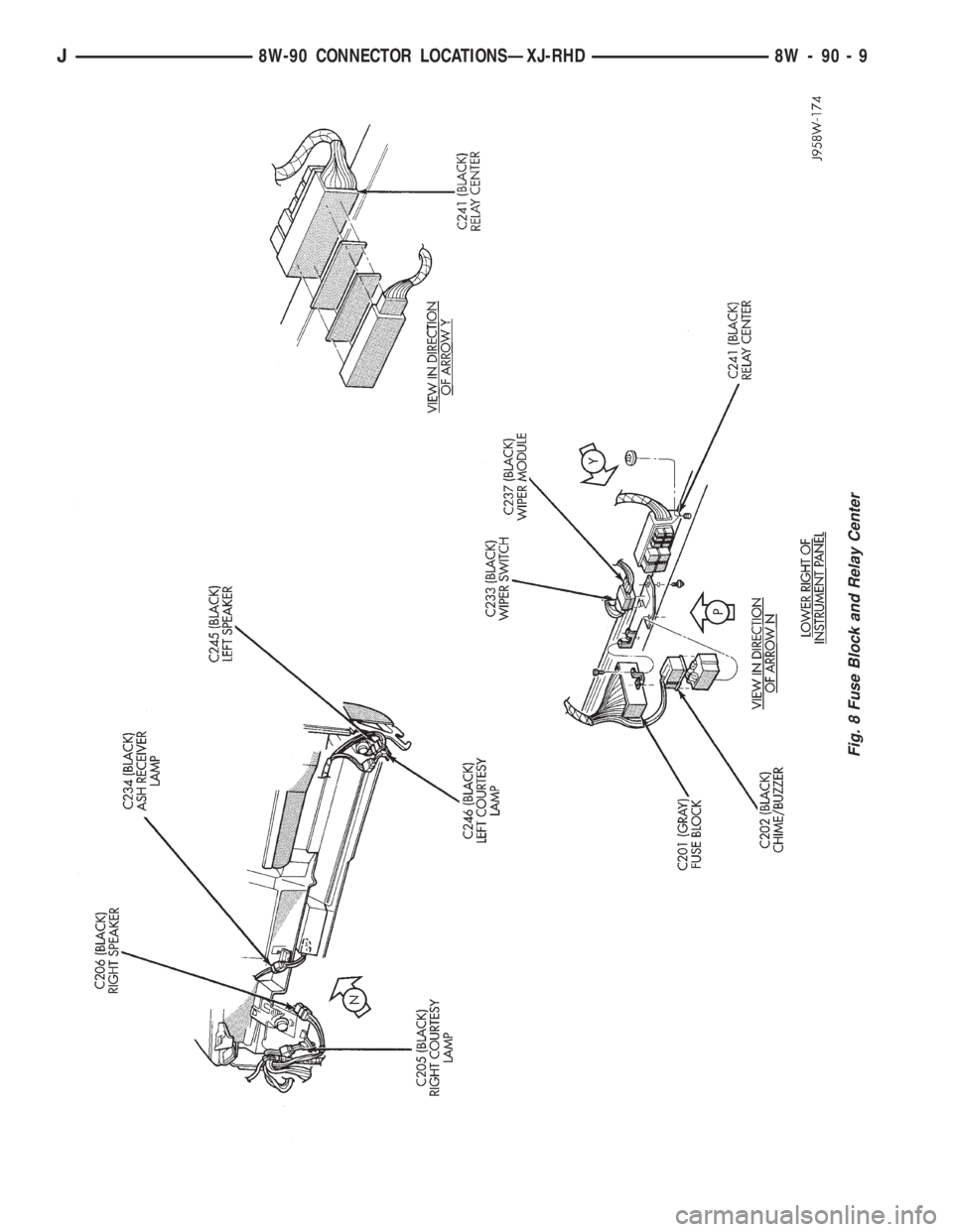
Fig. 8 Fuse Block and Relay Center
J8W-90 CONNECTOR LOCATIONSÐXJ-RHD 8W - 90 - 9
Page 1554 of 2198
(2) Verify transmission throttle cable operation.
Repair or replace cable if necessary.
(3) Check engine throttle operation. Operate accel-
erator pedal and observe injector throttle plate move-
ment. Adjust linkage if throttle plate does not reach
wide open position.
(4) Check transmission fluid level when fluid is at
normal operating temperature. Start engine. Shift
transmission through all gear ranges then back to
Neutral. Correct level is to Full or Add mark on dip-
stick with engine at curb idle speed.
(5) Check and adjust park/neutral position switch
if necessary.
(6) Check throttle position sensor adjustment and
operation. Adjust the sensor if necessary.
MANUAL SHIFTING TEST
(1) This test determines if problem is related to
mechanical or electrical component.
(2) Stop engine and disconnect transmission con-
trol module or module fuse.
(3) Road test vehicle. Shift transmission into each
gear range. Transmission should operate as follows:
²lock in Park
²back up in Reverse
²not move in Neutral
²provide first gear only with shift lever in 1-2 posi-
tion
²operate in third gear only with shift lever in 3 po-
sition
²operate in overdrive fourth gear in D position
(4) If transmission operates as described, proceed
to next step. However, if forward gear ranges were
difficult to distinguish (all feel the same), or vehicle
would not back up, refer to diagnosis charts. Do not
perform stall or time lag tests.
CAUTION: Do not overspeed the engine during the
next test step. Ease off the throttle and allow the
vehicle to slow before downshifting.
(5) Continue road test. Manually downshift trans-
mission from D to 3, and from 3 to 1-2 position. Then
manually upshift transmission through forward
ranges again.
(6) If transmission operation is OK, perform stall,
time lag and pressure tests. If transmission shifting
problem is encountered, refer to diagnosis charts.
(7) If a problem still exists, continue testing with
DRB scan tool.
HYDRAULIC PRESSURE TEST
PRESSURE TEST PROCEDURE
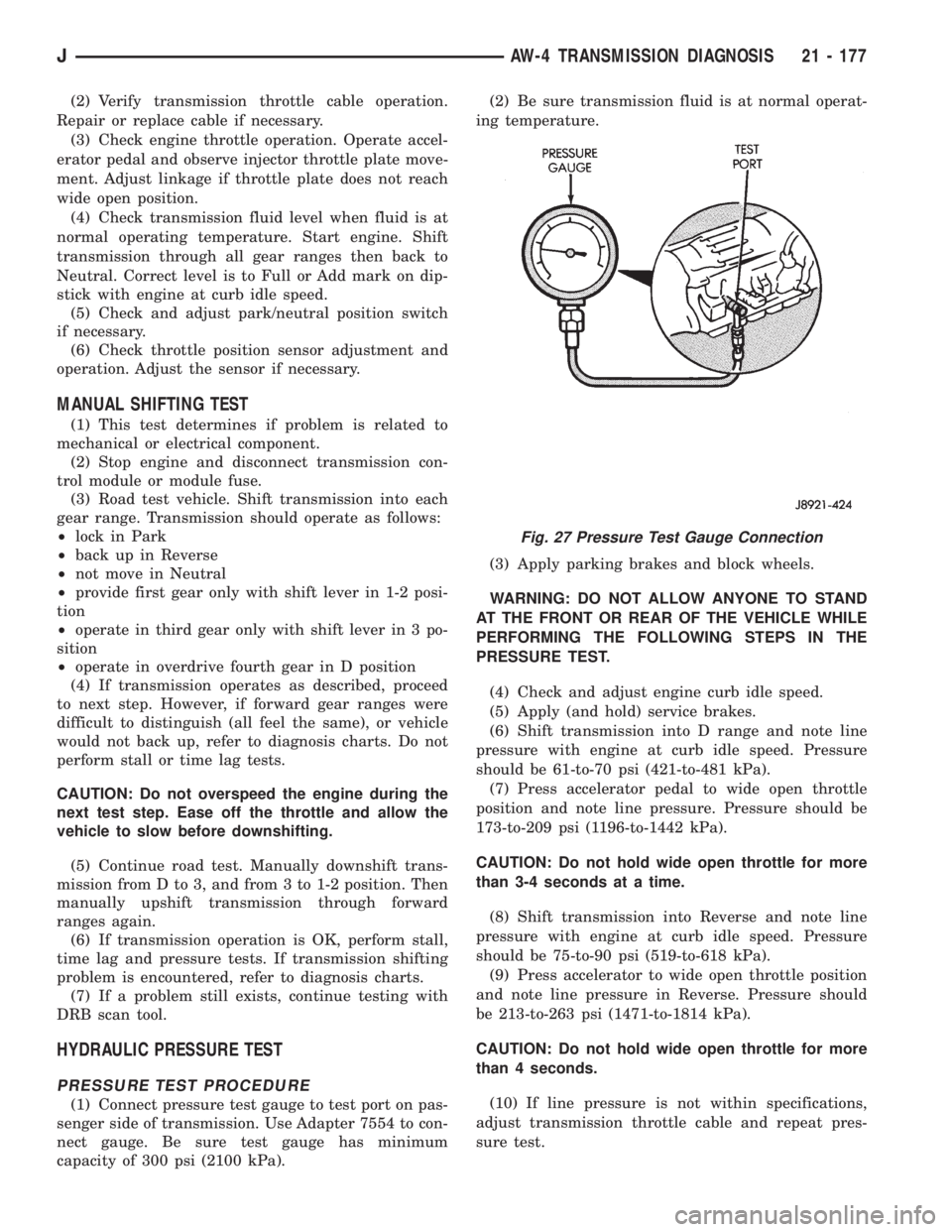
(1) Connect pressure test gauge to test port on pas-
senger side of transmission. Use Adapter 7554 to con-
nect gauge. Be sure test gauge has minimum
capacity of 300 psi (2100 kPa).(2) Be sure transmission fluid is at normal operat-
ing temperature.
(3) Apply parking brakes and block wheels.
WARNING: DO NOT ALLOW ANYONE TO STAND
AT THE FRONT OR REAR OF THE VEHICLE WHILE
PERFORMING THE FOLLOWING STEPS IN THE
PRESSURE TEST.
(4) Check and adjust engine curb idle speed.
(5) Apply (and hold) service brakes.
(6) Shift transmission into D range and note line
pressure with engine at curb idle speed. Pressure
should be 61-to-70 psi (421-to-481 kPa).
(7) Press accelerator pedal to wide open throttle
position and note line pressure. Pressure should be
173-to-209 psi (1196-to-1442 kPa).
CAUTION: Do not hold wide open throttle for more
than 3-4 seconds at a time.
(8) Shift transmission into Reverse and note line
pressure with engine at curb idle speed. Pressure
should be 75-to-90 psi (519-to-618 kPa).
(9) Press accelerator to wide open throttle position
and note line pressure in Reverse. Pressure should
be 213-to-263 psi (1471-to-1814 kPa).
CAUTION: Do not hold wide open throttle for more
than 4 seconds.
(10) If line pressure is not within specifications,
adjust transmission throttle cable and repeat pres-
sure test.
Fig. 27 Pressure Test Gauge Connection
JAW-4 TRANSMISSION DIAGNOSIS 21 - 177
Page 1969 of 2198
DIAGRAM INDEX; AIR CONDITIONING/
HEATER (XJ-RHD)..................8W-42-2
DIAGRAM INDEX; AIR CONDITIONING/
HEATER (YJ)...............8W-42-1,8W-42-2
DIAGRAM INDEX; ANTI-LOCK BRAKES
(XJ).............................8W-32-3
DIAGRAM INDEX; ANTI-LOCK BRAKES
(XJ-RHD).........................8W-32-3
DIAGRAM INDEX; ANTI-LOCK BRAKES
(YJ).............................8W-32-2
DIAGRAM INDEX; CHARGING SYSTEM
(XJ).............................8W-20-1
DIAGRAM INDEX; CHARGING SYSTEM
(XJ-RHD).........................8W-20-1
DIAGRAM INDEX; CHARGING SYSTEM
(YJ).............................8W-20-1
DIAGRAM INDEX; FRONT LIGHTING (XJ) . 8W-50-2
DIAGRAM INDEX; FRONT LIGHTING
(XJ-RHD).........................8W-50-3
DIAGRAM INDEX; FRONT LIGHTING (YJ) . 8W-50-2
DIAGRAM INDEX; FUEL/IGNITION (YJ) . . 8W-30-5
DIAGRAM INDEX; FUSE/FUSE BLOCK
(XJ).............................8W-10-1
DIAGRAM INDEX; FUSE/FUSE BLOCK
(XJ-RHD).........................8W-10-1
DIAGRAM INDEX; FUSE/FUSE BLOCK
(YJ).............................8W-10-1
DIAGRAM INDEX; GROUND
DISTRIBUTION (XJ)................8W-15-1
DIAGRAM INDEX; GROUND
DISTRIBUTION (XJ-RHD)............8W-15-1
DIAGRAM INDEX; GROUND
DISTRIBUTION (YJ)..................8W-15-1
DIAGRAM INDEX; HEATED REAR
WINDOW (XJ).....................8W-48-1
DIAGRAM INDEX; HEATED REAR
WINDOW (XJ-RHD).................8W-48-1
DIAGRAM INDEX; HEATED REAR
WINDOW (YJ).....................8W-48-1
DIAGRAM INDEX; HORN/CIGAR LIGHTER . . . 8E-1
DIAGRAM INDEX; HORN/CIGAR LIGHTER
(YJ).............................8W-41-1
DIAGRAM INDEX; INSTRUMENT
CLUSTER (XJ).............8W-40-1,8W-40-3
DIAGRAM INDEX; INSTRUMENT
CLUSTER (XJ-RHD)................8W-40-3
DIAGRAM INDEX; INSTRUMENT
CLUSTER (YJ).....................8W-40-2
DIAGRAM INDEX; INTERIOR LIGHTING
(XJ).............................8W-44-2
DIAGRAM INDEX; INTERIOR LIGHTING
(XJ-RHD).........................8W-44-2
DIAGRAM INDEX; INTERIOR LIGHTING
(YJ).............................8W-44-2
DIAGRAM INDEX; OVERHEAD CONSOLE
(XJ).............................8W-49-1
DIAGRAM INDEX; OVERHEAD CONSOLE
(XJ-RHD).........................8W-49-1
DIAGRAM INDEX; POWER DISTRIBUTION
(XJ).............................8W-11-1
DIAGRAM INDEX; POWER DISTRIBUTION
(XJ-RHD).........................8W-11-1
DIAGRAM INDEX; POWER DISTRIBUTION
(YJ).............................8W-11-1
DIAGRAM INDEX; POWER DOOR LOCKS
(XJ)
.............................8W-61-1
DIAGRAM INDEX; POWER DOOR LOCKS
(XJ-RHD)
.........................8W-61-1
DIAGRAM INDEX; POWER MIRRORS
(XJ)
.............................8W-62-1
DIAGRAM INDEX; POWER MIRRORS
(XJ-RHD)
.........................8W-62-1
DIAGRAM INDEX; POWER SEAT (XJ)
. . . 8W-63-1
DIAGRAM INDEX; POWER SEAT
(XJ-RHD)
.........................8W-63-1
DIAGRAM INDEX; POWER WINDOWS
(XJ)
.............................8W-60-2
DIAGRAM INDEX; POWER WINDOWS
(XJ-RHD)
.........................8W-60-2
DIAGRAM INDEX; REAR LIGHTING (XJ)
. 8W-51-1
DIAGRAM INDEX; REAR LIGHTING
(XJ-RHD)
.........................8W-51-1
DIAGRAM INDEX; REAR LIGHTING (YJ)
. 8W-51-1
DIAGRAM INDEX; STARTING SYSTEM
(XJ)
.............................8W-21-1
DIAGRAM INDEX; STARTING SYSTEM
(XJ-RHD)
.........................8W-21-1DIAGRAM INDEX; STARTING SYSTEM
(YJ).............................8W-21-1
DIAGRAM INDEX; TRAILER TOW (XJ) . . 8W-54-1
DIAGRAM INDEX; TRAILER TOW
(XJ-RHD).........................8W-54-1
DIAGRAM INDEX; TRANSMISSION
CONTROLS (XJ)...................8W-31-1
DIAGRAM INDEX; TRANSMISSION
CONTROLS (XJ-RHD)...............8W-31-1
DIAGRAM INDEX; TRANSMISSION
CONTROLS (YJ)...................8W-31-1
DIAGRAM INDEX; TURN SIGNALS (XJ) . 8W-52-1
DIAGRAM INDEX; TURN SIGNALS
(XJ-RHD).........................8W-52-1
DIAGRAM INDEX; TURN SIGNALS (YJ) . 8W-52-1
DIAGRAM INDEX; VEHICLE SPEED
CONTROL (XJ)....................8W-33-1
DIAGRAM INDEX; VEHICLE SPEED
CONTROL (XJ-RHD)................8W-33-1
DIAGRAM INDEX; WIPERS (XJ).......8W-53-2
DIAGRAM INDEX; WIPERS (XJ-RHD) . . . 8W-53-2
DIAGRAM INDEX; WIPERS (YJ).......8W-53-2
DIAGRAM INDEX; FUEL/IGNITION
(XJ-RHD).........................8W-30-5
DIAGRAM INDEXÐ2.5L ENGINE;
FUEL/IGNITION (XJ)................8W-30-6
DIAGRAM INDEXÐ4.0L ENGINE;
FUEL/IGNITION (XJ)................8W-30-6
DIFFERENTIAL AND PINION
MEASUREMENT.......................2-40
DIFFERENTIAL ASSEMBLY; FRONT
SUSPENSION AND AXLE.................2-38
DIFFERENTIAL ASSEMBLY; REAR
SUSPENSION AND AXLES...............3-21
DIFFERENTIAL DISASSEMBLY; FRONT
SUSPENSION AND AXLE................2-35
DIFFERENTIAL DISASSEMBLY; REAR
SUSPENSION AND AXLES...............3-18
DIFFERENTIAL INSTALLATION............2-44
DIFFERENTIAL, LIMITED SLIP............3-10
DIFFERENTIAL MEASUREMENT AND
INSTALLATION........................3-25
DIFFERENTIAL OVERHAUL..............3-46
DIFFERENTIAL REMOVAL; FRONT
SUSPENSION AND AXLE................2-34
DIFFERENTIAL REMOVAL; REAR
SUSPENSION AND AXLES...............3-18
DIFFERENTIAL SERVICE................3-34
DIFFERENTIAL SHIM PACK
MEASUREMENT AND ADJUSTMENT.......2-43
DIFFERENTIAL, TRAC-LOK..............3-45
DIMENSION DATA, VEHICLE.....Intro.-5,Intro.-6
DIMENSIONS, AW-4 VALVE BODY CHECK
BALL.............................21-341
DIMENSIONS, DESIGNATIONS,
LABELS/PLATES, CODES..............Intro.-1
DIMENSIONS, FRAME.............13-13,13-1
DIMMER SWITCH REMOVE/INSTALL,
HEADLAMP OR PANEL................8E-42
DIMMER SWITCH REPLACEMENTÐYJ,
HEADLAMP.........................8L-26
DIMMING MODULE; FRONT LIGHTING
(XJ-RHD).........................8W-50-1
DIODE REPLACEMENT; WIRING
DIAGRAMSÐGENERAL INFORMATION
(XJ)...............................8W-8
DIRECT CLUTCH OVERHAUL...........21-228
DISASSEMBLY AND INSPECTION, VALVE
BODY.............................21-147
DISASSEMBLY AND OVERHAUL,
TRANSFER CASE..............21-289,21-310
DISASSEMBLY AND OVERHAUL,
TRANSMISSION.................21-37,21-5
DISASSEMBLY, CALIPER................5-48
DISASSEMBLY, DIFFERENTIAL; FRONT
SUSPENSION AND AXLE................2-35
DISASSEMBLY, DIFFERENTIAL; REAR
SUSPENSION AND AXLES...............3-18
DISASSEMBLY, TRANSMISSION . . 21-119,21-201
DISASSEMBLYÐCOLUMN OR CONSOLE
SHIFT..............................19-60
DISC AND PLATE THICKNESS, AW-4
CLUTCH...........................21-338
DISC BRAKE ROTOR REFINISHING
........5-53
DISC BRAKE ROTOR RUNOUT
...........5-52
DISC BRAKE ROTOR THICKNESS
.........5-52
DISC BRAKES
........................5-45
DISC BRAKESHOE INSTALLATION
.........5-47DISC BRAKESHOE REMOVAL............5-46
DISC INSTALLATION, CLUTCH COVER.....6-10
DISC REMOVAL, CLUTCH COVER.........6-10
DISC RUNOUT, CLUTCH COVER...........6-3
DISCHARGE (ESD) SENSITIVE DEVICES,
ELECTROSTATIC; WIRING
DIAGRAMSÐGENERAL INFORMATION
(XJ)...............................8W-2
DISCONNECT AXLEÐYJ VEHICLES,
VACUUM............................2-27
DISCONNECT AXLE/SHIFT MOTOR
DIAGNOSIS..........................2-29
DISCONNECT AXLE/SHIFT MOTOR
DIAGNOSIS (CONT'D)..................2-30
DISPLAY, ABS WARNING LIGHT...........5-3
DISPLAY SYMBOLS, INTERNATIONAL
VEHICLE CONTROL..................Intro.-5
DISPLAY SYMBOLS, VEHICLE CONTROL . Intro.-10
DISPOSALÐXJ, LIFTGATE SUPPORT
ROD CYLINDER......................23-63
DISTRIBUTOR.......................8D-19
DISTRIBUTOR CAP....................8D-7
DISTRIBUTOR CAP AND ROTOR,
IGNITION CABLES.....................0-20
DISTRIBUTOR ROTOR.................8D-8
DISTRIBUTORS.......................8D-4
DOME LAMP, CARGO LAMP; INTERIOR
LIGHTING (XJ-RHD)................8W-44-1
DOME LAMP, CARGO LAMP, COURTESY
LAMPS; INTERIOR LIGHTING (XJ).....8W-44-1
DOME LAMP REPLACEMENTÐXJ.........8L-17
DOME LAMPÐXJ....................23-93
DOME LAMPS, COURTESY LAMPS;
INTERIOR LIGHTING (YJ)............8W-44-1
DOME/CARGO LAMP BULB
REPLACEMENTÐYJ VEHICLES,
HARDTOP..........................8L-31
DOME/COURTESY LAMP SERVICE
INFORMATIONÐXJ...................8L-16
DOME/COURTESY LAMP SERVICE
INFORMATIONÐYJ...................8L-31
DOME/COURTESY LAMP TROUBLE
DIAGNOSISÐXJ.....................8L-16
DOME/COURTESY LAMP TROUBLE
DIAGNOSISÐYJ.....................8L-31
DOOR ALIGNMENT ADJUSTMENTÐ
MAJOR............................23-41
DOOR ALIGNMENT ADJUSTMENTÐ
MINOR.............................23-37
DOOR ASSIST HANDLEÐYJ, FULL-
METAL............................23-136
DOOR BUMPERSÐXJ, FUEL FILLER.....23-27
DOOR CONTROL CABLES, VENT.........24-32
DOOR EDGE GUARD/EDGE PROTECTOR
STRIPÐXJ.........................23-54
DOOR EXTERNAL HANDLEÐXJ.........23-48
DOOR FRAME GLASS CHANNEL
REPLACEMENTÐYJ.................23-142
DOOR HINGE/HINGE PIN
REPLACEMENTÐXJ..................23-52
DOOR HINGESÐYJ, FULL-METAL.......23-140
DOOR INSIDE LATCH RELEASE AND
LOCK RODSÐXJ.....................23-50
DOOR JAMB SWITCH, DRIVER'S.....8U-1,8U-2
DOOR KEY LOCK CYLINDERÐXJ........23-47
DOOR KEY LOCK CYLINDERÐYJ,
FULL-METAL.......................23-139
DOOR LATCH ADJUSTMENTÐXJ........23-48
DOOR LATCH EXTERNAL RELEASE
HANDLEÐYJ, FULL-METAL............23-140
DOOR LATCH INSIDE RELEASE AND
LOCK HANDLEÐYJ, FULL-METAL.......23-137
DOOR LATCH STRIKERÐYJ, HALF-
METAL............................23-135
DOOR LATCHÐXJ....................23-49
DOOR LATCHÐYJ, FULL-METAL........23-140
DOOR LOCKS, POWER; POWER DOOR
LOCKS (XJ).......................8W-61-1
DOOR LOCKS, POWER; POWER DOOR
LOCKS (XJ-RHD)
..................8W-61-1
DOOR MIRROR (EXTERNAL)ÐYJ, HALF
METAL
............................23-121
DOOR MOTOR SWITCH REPLACEMENT,
BLOWER MOTOR/AIR
.................24-32
DOOR OPENER STORAGE, REMOTE
GARAGE
............................8C-1
DOOR OPENING WEATHERSTRIP
SEALSÐXJ, DOOR WINDOW GLASS
.....23-55
8 INDEXJ
Description Group-Page Description Group-Page Description Group-Page
Page 1970 of 2198
DOOR REMOVAL/INSTALLATIONÐXJ.....23-35
DOOR RESTRAINT REPLACEMENTÐXJ . . . 23-41
DOOR SERVICEÐYJ, FULL-METAL......23-142
DOOR SPACER BLOCKSÐTWO-DOOR
VEHICLES, FRONT....................23-53
DOOR STATIONARY WINDOW
GLASSÐXJ, REAR...................23-46
DOOR TRIM PANELÐXJ...............23-31
DOOR TRIM PANELÐYJ, FULL-METAL . . . 23-137
DOOR VACUUM MOTOR, FRESH AIR.....24-34
DOOR VACUUM MOTOR REPLACEMENT,
A/C RECIRCULATING..................24-27
DOOR VENT WINDOW GLASSÐYJ,
FULL-METAL.......................23-137
DOOR WATERDAMÐYJ, FULL-METAL . . . 23-137
DOOR WEATHERSTRIP SEAL
REPLACEMENTÐYJ.................23-142
DOOR WEATHERSTRIP SEALSÐYJ,
FULL-METAL.......................23-141
DOOR WINDOW EXTERIOR
MOLDINGSÐXJ.....................23-54
DOOR WINDOW GLASS AND DOOR
OPENING WEATHERSTRIP SEALSÐXJ....23-55
DOOR WINDOW GLASS REGULATOR
HANDLEÐYJ, FULL-METAL............23-136
DOOR WINDOW GLASS REGULATORÐ
XJ, FRONT..........................23-42
DOOR WINDOW GLASS REGULATORÐ
XJ, REAR...........................23-44
DOOR WINDOW GLASS REGULATORÐ
YJ, FULL-METAL....................23-138
DOOR WINDOW GLASSÐXJ, FRONT.....23-43
DOOR WINDOW GLASSÐXJ, REAR......23-45
DOOR WINDOW GLASSÐYJ, FULL-
METAL............................23-139
DOORÐYJ, HALF-METAL SOFT TOP.....23-134
DOUBLE CARDAN (CV)................16-11
DRAG LINK....................19-16,19-20
DRAINING COOLING SYSTEM............7-21
DRAW FUSE, IGNITION-OFF.............8F-1
DRAW, IGNITION-OFF.................8A-10
DRB SCAN TOOL; BRAKES...............5-3
DRB SCAN TOOL; COOLING SYSTEM.......7-5
DRB SCAN TOOL; EMISSION CONTROL
SYSTEMS...........................25-2
DRB SCAN TOOL; FUEL SYSTEM........14-54
DRB SCAN TOOL; IGNITION SYSTEMS....8D-8
DRIERÐ2.5L ENGINES, CONDENSER
FILTER.............................24-27
DRIERÐ4.0L ENGINES, FILTER.........24-28
DRIP RAIL MOLDINGÐXJ.............23-25
DRIVE (4WD) SWITCH, FOUR-WHEEL;
INSTRUMENT CLUSTER (XJ-RHD).....8W-40-2
DRIVE (4WD) SWITCH, FOUR-WHEEL;
TRANSMISSION CONTROLS (XJ-RHD) . . 8W-31-1
DRIVE, AUTOMATIC BELT TENSIONERÐ
XJ MODELS WITH RIGHT HAND..........7-42
DRIVE AXLE ASSEMBLY
REPLACEMENTÐXJ VEHICLES; FRONT
SUSPENSION AND AXLE................2-23
DRIVE AXLE ASSEMBLY
REPLACEMENTÐXJ VEHICLES; REAR
SUSPENSION AND AXLES...........3-14,3-31
DRIVE AXLE ASSEMBLY
REPLACEMENTÐYJ VEHICLES; FRONT
SUSPENSION AND AXLE................2-24
DRIVE AXLE ASSEMBLY
REPLACEMENTÐYJ VEHICLES; REAR
SUSPENSION AND AXLES
...............3-14
DRIVE AXLE, FRONT
....................2-3
DRIVE BELT, ACCESSORY
...............0-21
DRIVE BELT DIAGNOSIS (CONT.),
SERPENTINE
.........................7-40
DRIVE BELT DIAGNOSIS, SERPENTINE
.....7-39
DRIVE, BELT SERVICEÐEXCEPT RIGHT
HAND
...............................7-40
DRIVE, BELT SERVICEÐXJ MODELS
WITH RIGHT HAND
....................7-42
DRIVE BELT TENSION
..................7-45
DRIVE BELTS, ENGINE ACCESSORY
.......7-38
DRIVE GEAR, SPEED SENSOR
ROTORÐSPEEDOMETER
.............21-193
DRIVE, GENERATOR REMOVE/INSTALLÐ
LEFT-HAND
..........................8B-6
DRIVE, GENERATOR REMOVE/INSTALLÐ
RIGHT-HAND
.........................8B-7
DRIVE PULLEY REPLACEMENT
..........19-13DRIVE (RHD), BELT TENSIONÐEXCEPT
RIGHT HAND.........................7-38
DRIVE (RHD), BELT TENSIONÐRIGHT
HAND...............................7-38
DRIVE (RHD) MODELS, BELT TENSIONÐ
EXCEPT RIGHT HAND..................7-45
DRIVE SHAFTS.......................0-26
DRIVE VEHICLES, RIGHT HAND..........23-1
DRIVE, VISCOUS FAN..................7-34
DRIVELINE SNAP; FRONT SUSPENSION
AND AXLE...........................2-19
DRIVELINE SNAP; REAR SUSPENSION
AND AXLES..........................3-10
DRIVELINE VIBRATION.................16-3
DRIVER'S DOOR JAMB SWITCH.....8U-1,8U-2
DRIVER'S POWER LOCK SWITCHÐ2-
DOOR (LHD).........................8P-3
DRIVER'S POWER LOCK SWITCHÐ2-
DOOR (RHD).........................8P-4
DRIVER'S POWER LOCK SWITCHÐ4-
DOOR..............................8P-5
DRIVER'S POWER WINDOW SWITCHÐ
2-DOOR (LHD).......................8S-4
DRIVER'S POWER WINDOW SWITCHÐ
2-DOOR (RHD).......................8S-5
DRIVER'S POWER WINDOW SWITCHÐ
4-DOOR.............................8S-3
DRIVER'S SEAT BELT SWITCH.......8U-1,8U-3
DRIVETRAIN.........................0-22
DRL MODULE REPLACEMENTÐXJ.......8L-15
DRL MODULE REPLACEMENTÐYJ........8L-30
DRUM BRAKE ADJUSTMENT............5-57
DRUM BRAKES.......................5-55
DRUM BRAKESHOE INSTALLATION.......5-55
DRUM BRAKESHOE REMOVAL...........5-55
DRUM REFINISHING, BRAKE............5-58
DRUMÐREAR SUPPORT OVERHAUL,
OVERRUNNING CLUTCHÐLOW-
REVERSE..........................21-125
DUCT, DEFROSTER NOZZLE............24-33
DUCT, FRESH AIR INTAKE..............24-34
ECU AND HCU DIAGNOSIS, ANTILOCK......5-3
ECU INSTALLATION (XJ MODELS)........5-40
ECU OPERATION......................5-37
ECU REMOVAL (XJ MODELS)............5-40
ECU REMOVAL/INSTALLATION (YJ
MODELS)............................5-41
EDGE GUARD/EDGE PROTECTOR
STRIPÐXJ, DOOR....................23-54
EFFECTS OF INCORRECT FLUID LEVEL....21-71
EFFORT, HARD PEDAL OR HIGH PEDAL.....5-6
ELECTRIC COOLING FANÐXJ MODELS
WITH 4.0L 6-CYLINDER ENGINE,
AUXILIARY..........................7-35
ELECTRICAL CONTROL, FUEL PUMP......14-5
ELECTRONIC CONTROL UNIT (ECU).......5-34
ELECTROSTATIC DISCHARGE (ESD)
SENSITIVE DEVICES; WIRING
DIAGRAMSÐGENERAL INFORMATION
(XJ)...............................8W-2
ELEMENT, AIR CLEANER; EMISSION
CONTROL SYSTEMS...................25-7
ELEMENT, AIR CLEANER; FUEL SYSTEM . . 14-59
ELEMENT, AIR CLEANER; LUBRICATION
AND MAINTENANCE...................0-18
ELEMENT TEST, OXYGEN SENSOR (O2S)
HEATING...........................14-48
ELEMENTS, HEATER; POWER MIRRORS
(XJ-RHD).........................8W-62-1
EMISSION CONTROL INFORMATION
(VECI) LABEL, VEHICLE.................25-1
EMISSION CONTROL SYSTEM...........0-20
EMISSION CONTROL SYSTEM
MAINTENANCE........................0-4
EMISSION CONTROLS..................25-4
EMR LAMPÐPCM OUTPUT............14-27
ENGINE ACCESSORY DRIVE BELTS.......7-38
ENGINE AND TRANSMISSION/TRANSFER
CASE IDENTIFICATION...............Intro.-5
ENGINE ASSEMBLY (SHORT BLOCK),
SERVICE.............................9-4
ENGINE ASSEMBLYÐXJ VEHICLES
. . . 9-18,9-59
ENGINE ASSEMBLYÐYJ VEHICLES
. . . 9-20,9-62
ENGINE, AUXILIARY ELECTRIC COOLING
FANÐXJ MODELS WITH 4.0L
6-CYLINDER
.........................7-35
ENGINE BLOCK HEATER
................7-44
ENGINE BREAK-IN
.....................0-15ENGINE COOLANT TEMPERATURE
GAUGE; INSTRUMENT CLUSTER (XJ) . . 8W-40-1
ENGINE COOLANT TEMPERATURE
SENSOR; FUEL SYSTEM...............14-60
ENGINE COOLANT TEMPERATURE
SENSOR; FUEL/IGNITION (XJ)........8W-30-3
ENGINE COOLANT TEMPERATURE
SENSOR; FUEL/IGNITION (YJ)........8W-30-3
ENGINE COOLANT TEMPERATURE
SENSOR; IGNITION SYSTEMS......8D-19,8D-5
ENGINE COOLANT TEMPERATURE
SENSOR; FUEL/IGNITION (XJ-RHD)....8W-30-3
ENGINE COOLANT TEMPERATURE
SENSOR TEST; FUEL SYSTEM..........14-46
ENGINE COOLANT TEMPERATURE
SENSOR TEST; IGNITION SYSTEMS.......8D-9
ENGINE COOLANT TEMPERATURE
SENSORÐPCM INPUT................14-23
ENGINE COOLANT TEMPERATURE
WARNING LAMP; INSTRUMENT
CLUSTER (XJ).....................8W-40-1
ENGINE COOLANT TEMPERATURE
WARNING LAMP; INSTRUMENT
CLUSTER (XJ-RHD)................8W-40-1
ENGINE COOLING SYSTEM..............0-18
ENGINE CYLINDER HEAD...........9-25,9-67
ENGINE CYLINDER HEAD COVER.....9-22,9-64
ENGINE CYLINDER HEAD GASKET
FAILURE DIAGNOSIS....................9-5
ENGINE DAMPER.....................9-17
ENGINE DIAGNOSIS....................9-5
ENGINE, DIAGRAM INDEXÐ2.5L;
FUEL/IGNITION (XJ)..................8W-30-6
ENGINE, DIAGRAM INDEXÐ4.0L;
FUEL/IGNITION (XJ)................8W-30-6
ENGINE, ENGINE EXHAUST MANIFOLDÐ
2.5L................................11-7
ENGINE, ENGINE EXHAUST MANIFOLDÐ
4.0L................................11-7
ENGINE, ENGINE FIRING ORDERÐ2.5L
4-CYLINDER........................8D-32
ENGINE, ENGINE FIRING ORDERÐ4.0L
6-CYLINDER........................8D-32
ENGINE EXHAUST MANIFOLDÐ2.5L
ENGINE.............................11-7
ENGINE EXHAUST MANIFOLDÐ4.0L
ENGINE.............................11-7
ENGINE FIRING ORDERÐ2.5L
4-CYLINDER ENGINE.................8D-32
ENGINE FIRING ORDERÐ4.0L
6-CYLINDER ENGINE.................8D-32
ENGINE, INTAKE MANIFOLDÐ2.5L........11-7
ENGINE, INTAKE MANIFOLDÐ4.0L........11-8
ENGINE MAINTENANCE.................0-15
ENGINE MOUNTÐREAR............9-16,9-57
ENGINE MOUNTSÐFRONT..........9-14,9-56
ENGINE OIL..........................0-15
ENGINE OIL CHANGE AND FILTER
REPLACEMENT.......................0-16
ENGINE OIL FILTER....................0-17
ENGINE OIL PRESSURE.................9-7
ENGINE ONLY, POWER STEERING
PRESSURE SWITCHÐ2.5L.............14-63
ENGINE ONLY, TORQUE CONVERTER
CLUTCH (TCC) SOLENOID AND
RELAYÐ2.5L; TRANSMISSION
CONTROLS (XJ)...................8W-31-1
ENGINE ONLY, TRANSMISSION
CONTROL MODULEÐ4.0L;
TRANSMISSION CONTROLS (XJ)......8W-31-1
ENGINE PERFORMANCE.................9-2
ENGINE SERVICE PROCEDURES, 2.5L.....9-13
ENGINE SERVICE PROCEDURES, 4.0L.....9-55
ENGINE SPECIFICATIONS...........9-52,9-93
ENGINE, VACUUM ROUTING
SCHEMATICÐ2.5L 4 CYLINDER..........25-3
ENGINE, VACUUM ROUTING
SCHEMATICÐ4.0L 6 CYLINDER..........25-3
ENGINES, CONDENSER FILTER
DRIERÐ2.5L........................24-27
ENGINES, CONDENSERÐ4.0L..........24-28
ENGINES, FILTER DRIERÐ4.0L
.........24-28
ENGINES, FUEL USAGE STATEMENTÐ
GAS
................................0-19
ENGLISH/SAE CONVERSION, METRIC
. . Intro.-11
ENTRY MODULE, KEYLESS
.........8P-1,8P-7
ENTRY MODULE, REMOTE KEYLESS;
POWER DOOR LOCKS (XJ)
...........8W-61-1
JINDEX 9
Description Group-Page Description Group-Page Description Group-Page