1995 JEEP CHEROKEE Fuse block
[x] Cancel search: Fuse blockPage 886 of 2198
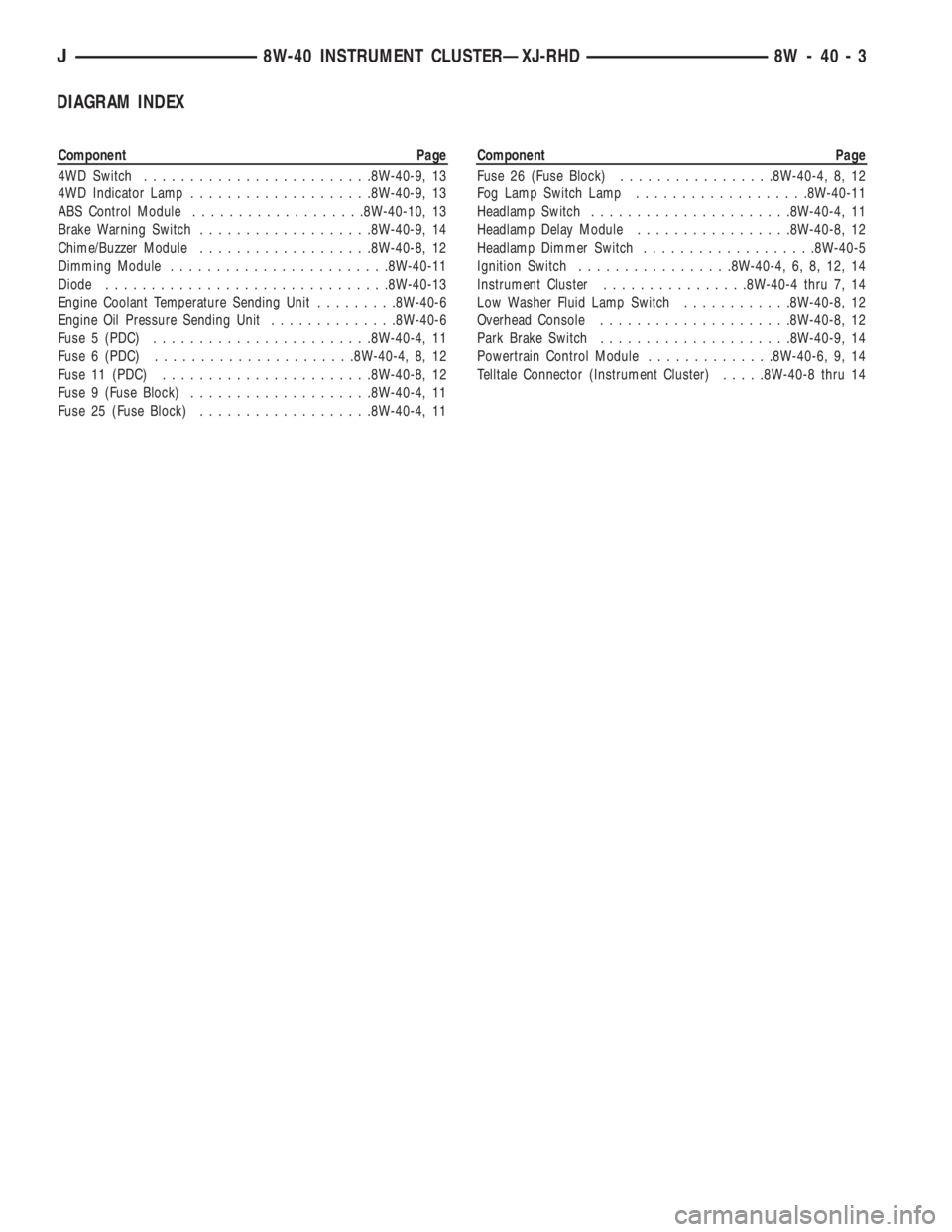
DIAGRAM INDEX
Component Page
4WD Switch.........................8W-40-9, 13
4WD Indicator Lamp....................8W-40-9, 13
ABS Control Module...................8W-40-10, 13
Brake Warning Switch...................8W-40-9, 14
Chime/Buzzer Module...................8W-40-8, 12
Dimming Module........................8W-40-11
Diode...............................8W-40-13
Engine Coolant Temperature Sending Unit.........8W-40-6
Engine Oil Pressure Sending Unit..............8W-40-6
Fuse 5 (PDC)........................8W-40-4, 11
Fuse 6 (PDC)......................8W-40-4, 8, 12
Fuse 11 (PDC).......................8W-40-8, 12
Fuse 9 (Fuse Block)....................8W-40-4, 11
Fuse 25 (Fuse Block)...................8W-40-4, 11Component Page
Fuse 26 (Fuse Block).................8W-40-4, 8, 12
Fog Lamp Switch Lamp...................8W-40-11
Headlamp Switch......................8W-40-4, 11
Headlamp Delay Module.................8W-40-8, 12
Headlamp Dimmer Switch...................8W-40-5
Ignition Switch.................8W-40-4, 6, 8, 12, 14
Instrument Cluster................8W-40-4 thru 7, 14
Low Washer Fluid Lamp Switch............8W-40-8, 12
Overhead Console.....................8W-40-8, 12
Park Brake Switch.....................8W-40-9, 14
Powertrain Control Module..............8W-40-6, 9, 14
Telltale Connector (Instrument Cluster).....8W-40-8 thru 14
J8W-40 INSTRUMENT CLUSTERÐXJ-RHD 8W - 40 - 3
Page 898 of 2198
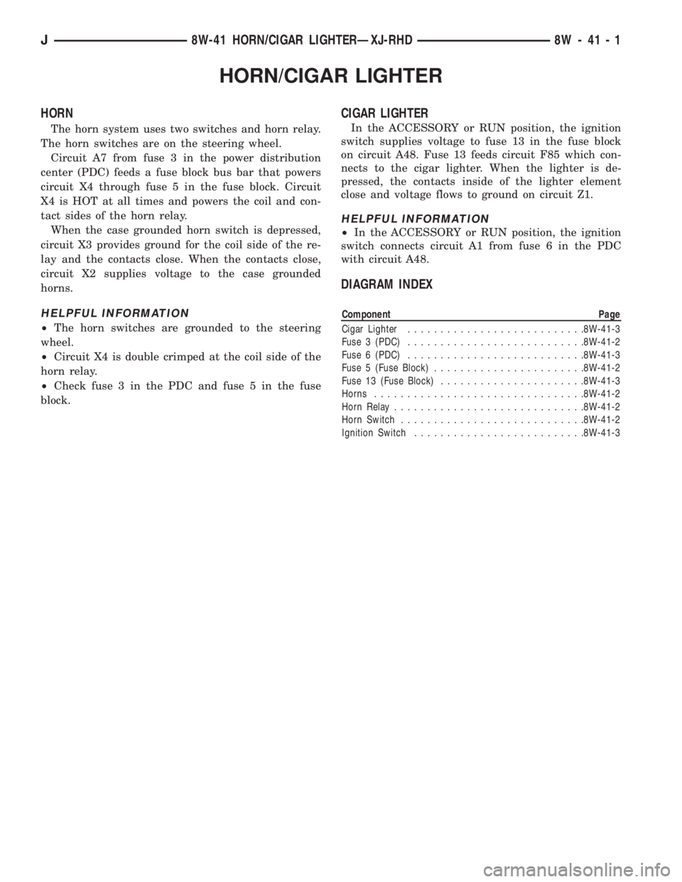
HORN/CIGAR LIGHTER
HORN
The horn system uses two switches and horn relay.
The horn switches are on the steering wheel.
Circuit A7 from fuse 3 in the power distribution
center (PDC) feeds a fuse block bus bar that powers
circuit X4 through fuse 5 in the fuse block. Circuit
X4 is HOT at all times and powers the coil and con-
tact sides of the horn relay.
When the case grounded horn switch is depressed,
circuit X3 provides ground for the coil side of the re-
lay and the contacts close. When the contacts close,
circuit X2 supplies voltage to the case grounded
horns.
HELPFUL INFORMATION
²The horn switches are grounded to the steering
wheel.
²Circuit X4 is double crimped at the coil side of the
horn relay.
²Check fuse 3 in the PDC and fuse 5 in the fuse
block.
CIGAR LIGHTER
In the ACCESSORY or RUN position, the ignition
switch supplies voltage to fuse 13 in the fuse block
on circuit A48. Fuse 13 feeds circuit F85 which con-
nects to the cigar lighter. When the lighter is de-
pressed, the contacts inside of the lighter element
close and voltage flows to ground on circuit Z1.
HELPFUL INFORMATION
²In the ACCESSORY or RUN position, the ignition
switch connects circuit A1 from fuse 6 in the PDC
with circuit A48.
DIAGRAM INDEX
Component Page
Cigar Lighter...........................8W-41-3
Fuse 3 (PDC)...........................8W-41-2
Fuse 6 (PDC)...........................8W-41-3
Fuse 5 (Fuse Block).......................8W-41-2
Fuse 13 (Fuse Block)......................8W-41-3
Horns................................8W-41-2
Horn Relay.............................8W-41-2
Horn Switch............................8W-41-2
Ignition Switch..........................8W-41-3
J8W-41 HORN/CIGAR LIGHTERÐXJ-RHD 8W - 41 - 1
Page 902 of 2198
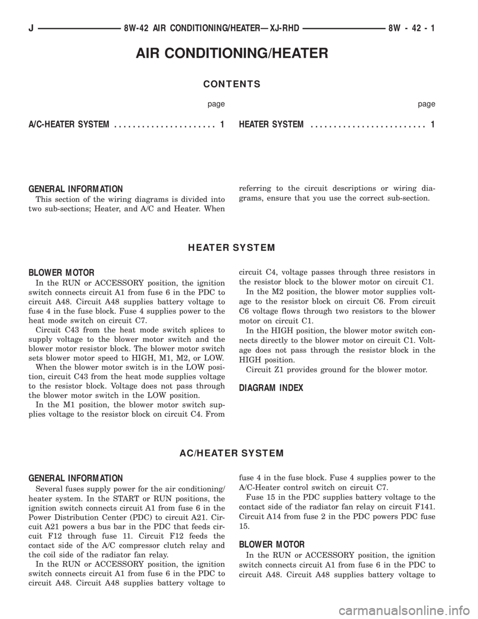
AIR CONDITIONING/HEATER
CONTENTS
page page
A/C-HEATER SYSTEM...................... 1 HEATERSYSTEM......................... 1
GENERAL INFORMATION
This section of the wiring diagrams is divided into
two sub-sections; Heater, and A/C and Heater. Whenreferring to the circuit descriptions or wiring dia-
grams, ensure that you use the correct sub-section.
HEATER SYSTEM
BLOWER MOTOR
In the RUN or ACCESSORY position, the ignition
switch connects circuit A1 from fuse 6 in the PDC to
circuit A48. Circuit A48 supplies battery voltage to
fuse 4 in the fuse block. Fuse 4 supplies power to the
heat mode switch on circuit C7.
Circuit C43 from the heat mode switch splices to
supply voltage to the blower motor switch and the
blower motor resistor block. The blower motor switch
sets blower motor speed to HIGH, M1, M2, or LOW.
When the blower motor switch is in the LOW posi-
tion, circuit C43 from the heat mode supplies voltage
to the resistor block. Voltage does not pass through
the blower motor switch in the LOW position.
In the M1 position, the blower motor switch sup-
plies voltage to the resistor block on circuit C4. Fromcircuit C4, voltage passes through three resistors in
the resistor block to the blower motor on circuit C1.
In the M2 position, the blower motor supplies volt-
age to the resistor block on circuit C6. From circuit
C6 voltage flows through two resistors to the blower
motor on circuit C1.
In the HIGH position, the blower motor switch con-
nects directly to the blower motor on circuit C1. Volt-
age does not pass through the resistor block in the
HIGH position.
Circuit Z1 provides ground for the blower motor.
DIAGRAM INDEX
AC/HEATER SYSTEM
GENERAL INFORMATION
Several fuses supply power for the air conditioning/
heater system. In the START or RUN positions, the
ignition switch connects circuit A1 from fuse 6 in the
Power Distribution Center (PDC) to circuit A21. Cir-
cuit A21 powers a bus bar in the PDC that feeds cir-
cuit F12 through fuse 11. Circuit F12 feeds the
contact side of the A/C compressor clutch relay and
the coil side of the radiator fan relay.
In the RUN or ACCESSORY position, the ignition
switch connects circuit A1 from fuse 6 in the PDC to
circuit A48. Circuit A48 supplies battery voltage tofuse 4 in the fuse block. Fuse 4 supplies power to the
A/C-Heater control switch on circuit C7.
Fuse 15 in the PDC supplies battery voltage to the
contact side of the radiator fan relay on circuit F141.
Circuit A14 from fuse 2 in the PDC powers PDC fuse
15.
BLOWER MOTOR
In the RUN or ACCESSORY position, the ignition
switch connects circuit A1 from fuse 6 in the PDC to
circuit A48. Circuit A48 supplies battery voltage to
J8W-42 AIR CONDITIONING/HEATERÐXJ-RHD 8W - 42 - 1
Page 903 of 2198
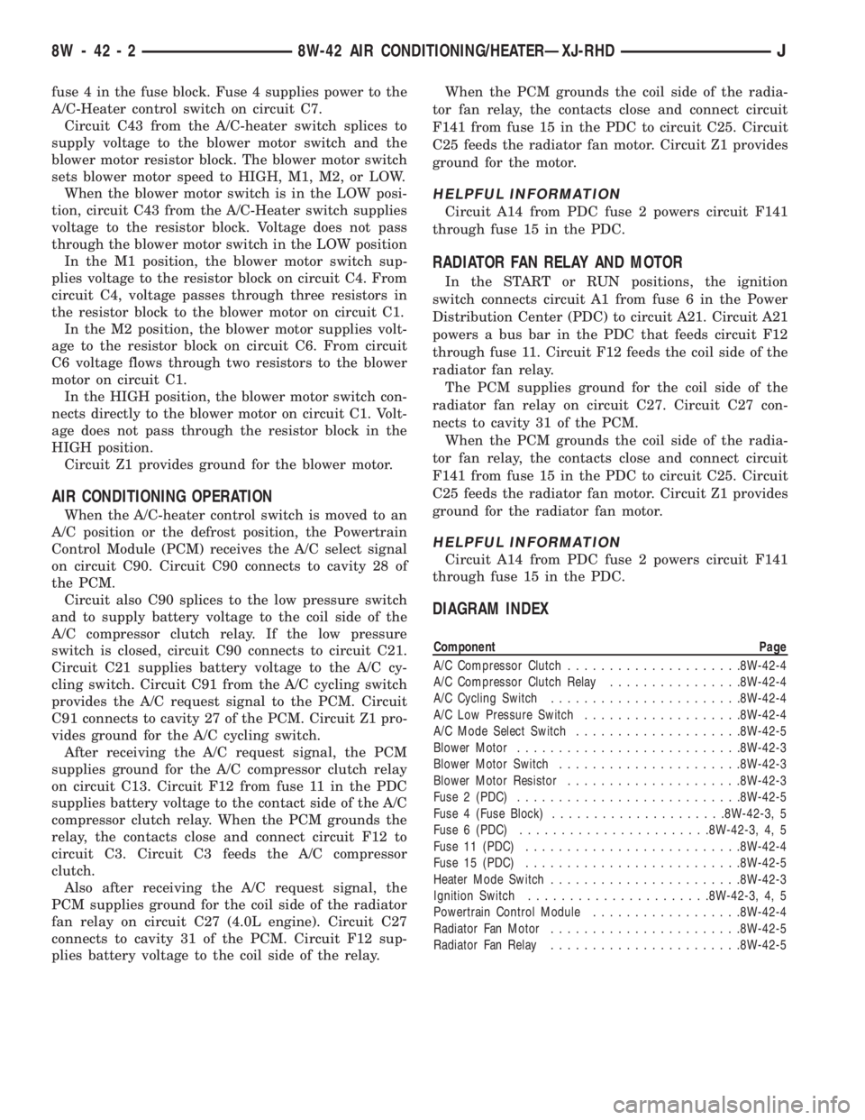
fuse 4 in the fuse block. Fuse 4 supplies power to the
A/C-Heater control switch on circuit C7.
Circuit C43 from the A/C-heater switch splices to
supply voltage to the blower motor switch and the
blower motor resistor block. The blower motor switch
sets blower motor speed to HIGH, M1, M2, or LOW.
When the blower motor switch is in the LOW posi-
tion, circuit C43 from the A/C-Heater switch supplies
voltage to the resistor block. Voltage does not pass
through the blower motor switch in the LOW position
In the M1 position, the blower motor switch sup-
plies voltage to the resistor block on circuit C4. From
circuit C4, voltage passes through three resistors in
the resistor block to the blower motor on circuit C1.
In the M2 position, the blower motor supplies volt-
age to the resistor block on circuit C6. From circuit
C6 voltage flows through two resistors to the blower
motor on circuit C1.
In the HIGH position, the blower motor switch con-
nects directly to the blower motor on circuit C1. Volt-
age does not pass through the resistor block in the
HIGH position.
Circuit Z1 provides ground for the blower motor.
AIR CONDITIONING OPERATION
When the A/C-heater control switch is moved to an
A/C position or the defrost position, the Powertrain
Control Module (PCM) receives the A/C select signal
on circuit C90. Circuit C90 connects to cavity 28 of
the PCM.
Circuit also C90 splices to the low pressure switch
and to supply battery voltage to the coil side of the
A/C compressor clutch relay. If the low pressure
switch is closed, circuit C90 connects to circuit C21.
Circuit C21 supplies battery voltage to the A/C cy-
cling switch. Circuit C91 from the A/C cycling switch
provides the A/C request signal to the PCM. Circuit
C91 connects to cavity 27 of the PCM. Circuit Z1 pro-
vides ground for the A/C cycling switch.
After receiving the A/C request signal, the PCM
supplies ground for the A/C compressor clutch relay
on circuit C13. Circuit F12 from fuse 11 in the PDC
supplies battery voltage to the contact side of the A/C
compressor clutch relay. When the PCM grounds the
relay, the contacts close and connect circuit F12 to
circuit C3. Circuit C3 feeds the A/C compressor
clutch.
Also after receiving the A/C request signal, the
PCM supplies ground for the coil side of the radiator
fan relay on circuit C27 (4.0L engine). Circuit C27
connects to cavity 31 of the PCM. Circuit F12 sup-
plies battery voltage to the coil side of the relay.When the PCM grounds the coil side of the radia-
tor fan relay, the contacts close and connect circuit
F141 from fuse 15 in the PDC to circuit C25. Circuit
C25 feeds the radiator fan motor. Circuit Z1 provides
ground for the motor.
HELPFUL INFORMATION
Circuit A14 from PDC fuse 2 powers circuit F141
through fuse 15 in the PDC.
RADIATOR FAN RELAY AND MOTOR
In the START or RUN positions, the ignition
switch connects circuit A1 from fuse 6 in the Power
Distribution Center (PDC) to circuit A21. Circuit A21
powers a bus bar in the PDC that feeds circuit F12
through fuse 11. Circuit F12 feeds the coil side of the
radiator fan relay.
The PCM supplies ground for the coil side of the
radiator fan relay on circuit C27. Circuit C27 con-
nects to cavity 31 of the PCM.
When the PCM grounds the coil side of the radia-
tor fan relay, the contacts close and connect circuit
F141 from fuse 15 in the PDC to circuit C25. Circuit
C25 feeds the radiator fan motor. Circuit Z1 provides
ground for the radiator fan motor.
HELPFUL INFORMATION
Circuit A14 from PDC fuse 2 powers circuit F141
through fuse 15 in the PDC.
DIAGRAM INDEX
Component Page
A/C Compressor Clutch.....................8W-42-4
A/C Compressor Clutch Relay................8W-42-4
A/C Cycling Switch.......................8W-42-4
A/C Low Pressure Switch...................8W-42-4
A/C Mode Select Switch....................8W-42-5
Blower Motor...........................8W-42-3
Blower Motor Switch......................8W-42-3
Blower Motor Resistor.....................8W-42-3
Fuse 2 (PDC)...........................8W-42-5
Fuse 4 (Fuse Block).....................8W-42-3, 5
Fuse 6 (PDC).......................8W-42-3, 4, 5
Fuse 11 (PDC)..........................8W-42-4
Fuse 15 (PDC)..........................8W-42-5
Heater Mode Switch.......................8W-42-3
Ignition Switch......................8W-42-3, 4, 5
Powertrain Control Module..................8W-42-4
Radiator Fan Motor.......................8W-42-5
Radiator Fan Relay.......................8W-42-5
8W - 42 - 2 8W-42 AIR CONDITIONING/HEATERÐXJ-RHDJ
Page 908 of 2198
INTERIOR LIGHTING
INDEX
page page
Cargo Lamp and Dome Lamp................. 1
Chime/Buzzer Module....................... 2
Diagram Index............................ 2
General Information........................ 1
Glove Box Lamp........................... 1Ignition Switch Lamp........................ 1
Instrument Panel Illumination Lamps............ 1
Reading Lamps........................... 1
Underhood Lamp.......................... 1
Visor Vanity Mirror Lamps.................... 1
GENERAL INFORMATION
Circuit M1 supplies power to the glove box lamp,
dome lamp, reading lamps, cargo lamp and vanity
lamps. Circuit M1 is protected by fuse 16 in the
Power Distribution Center (PDC).
Circuit E2 supplies power for the instrument panel
illumination lamps.
INSTRUMENT PANEL ILLUMINATION LAMPS
Circuit E2 from the headlamp switch splices to
supply power to the following illumination lamps:
²Ash receiver lamp
²Cigar lighter lamp
²Transmission range indicator lamp
²Transfer case range indicator lamp
²A/C-Heater switch lamp
²Heated rear window switch lamp
²Rear wiper switch lamp
²Fog lamp switch lamp
Fuse 25 in the fuse block protects circuit E2. Cir-
cuit Z1 provides ground for all of the illumination
lamps except for the cigar lighter lamp. The cigar
lighter lamp is case grounded.
HELPFUL INFORMATION
Circuit E2 also supplies power to the radio, LCD
relay and the illumination lamps in the instrument
cluster.
IGNITION SWITCH LAMP
Circuit M50 supplies voltage to the ignition switch
lamp. Circuit Z1 provides ground for the lamp.
GLOVE BOX LAMP
Circuit M1 from fuse 16 in the Power Distribution
Center (PDC) powers the glove box lamp. A case
grounded switch, in series after the lamp, closes
when the glove box door is opened. The switch com-
pletes a path to ground on circuit Z1.
CARGO LAMP AND DOME LAMP
Circuit M1 from fuse 16 in the Power Distribution
Center (PDC) supplies power to the cargo lamp anddome lamp. The M1 circuit is HOT at all times. The
ground path for the lamp is provided in three differ-
ent ways.
One way is through the door jamb switches. Circuit
M2 connects to the door jamb switches to the dome
lamp and cargo lamp. The switches are connected to
ground circuit Z1. When a door is opened, the
plunger in the switch closes, completing a path to
ground.
The second way is through the liftgate switch. Cir-
cuit G71 connects to circuit M2 at the cargo lamp
connector. Circuit G71 connects to the liftgate switch.
The liftgate switch connects to ground circuit Z1.
When the lift gate opens, the plunger in the switch
closes, completing a path to ground.
The third ground path is through the headlamp
switch. Circuit M2 is spliced in with the headlamp
switch. When the operator turns the headlamp
switch to the dome lamp ON position, a ground path
is provided through the switch.
READING LAMPS
Circuit M1 from fuse 16 in the Power Distribution
Center (PDC) supplies power to the reading lamps.
Circuit M1 is HOT at all times. When the operator
depresses the reading lamp, the reading lamp switch
closes and supplies ground on circuit Z1.
VISOR VANITY MIRROR LAMPS
Circuit M1 from fuse 16 in the Power Distribution
Center (PDC) supplies power to the vanity lamps.
Circuit M1 is HOT at all times. When the vanity
lamps switch closes, voltage flows to vanity mirror
lamps. The vanity mirror is case grounded.
UNDERHOOD LAMP
Circuit A7 from fuse 16 in the Power Distribution
Center (PDC) supplies battery voltage for the under-
hood lamp. A mercury switch, in series after the
lamp, connects the lamp to ground on circuit Z1.
When the hood is raised, mercury inside the switch
moves to a position where it connects circuit M1 to
ground circuit Z1, illuminating the lamp.
J8W-44 INTERIOR LIGHTINGÐXJ-RHD 8W - 44 - 1
Page 909 of 2198
CHIME/BUZZER MODULE
The buzzer or optional chime module sounds an au-
dible warning tone. The tone sounds for seat belt
warning and when the ignition key is in the ignition
switch while the drivers door is open. The tone also
sounds when the ignition key is in the ON position
while the drivers side seat belt is not buckled. Lastly,
the tone sounds when the headlamps are ON when
the ignition is OFF. Refer to Group 8U for system op-
eration.
When the ignition switch is in the RUN or START
position, fuse F87 from fuse 26 in the fuse block sup-
plies power to the chime/buzzer module. Circuit A21
from the ignition switch supplies power to fuse 26.
Circuit L7 from fuse 9 in the fuse block also sup-
plies power to the chime/buzzer module. Circuit A3
from fuse 5 in the Power Distribution Center (PDC)
powers fuse 9.
When the parking lamps or headlamps are ON, the
headlamp switch connects circuit G26 with the driv-
ers side door jamb switch. Circuit G26 also connects
to the key-in switch. Circuit M11 connects the key-in
switch to the chime module and the headlamp
switch.
If the headlamps are ON, and the drivers door
opens, ground for the chime/buzzer is on circuit C26
from the headlamp switch through the door jamb
switch to circuit Z1.
If the headlamps are OFF with the key in the ig-
nition while the drivers side door is open, ground for
the chime/buzzer is supplied through the key-in
switch. The ground path is over circuit M11, through
the closed key-in switch to circuit C26. From circuit
C26, the ground path continues through the drivers
door jamb switch to circuit Z1.
Circuit G11 from the buzzer powers the seat belt
warning lamp in the instrument cluster. Circuit Z1
at the instrument cluster provides ground for the
lamp.Circuit G10 from the buzzer connects to the seat
belt switch. When the seat belt switch closes a path
to ground is completed on circuit Z1 and the tone
sounds momentarily.
Circuit Z1 also grounds the chime buzzer module.
HELPFUL INFORMATION
Circuit F87 also powers the instrument cluster and
the headlamp delay module.
DIAGRAM INDEX
Component Page
Cargo Lamp............................8W-44-6
Chime/Buzzer Module......................8W-44-3
Courtesy Lamps.........................8W-44-5
Dome Lamp............................8W-44-6
Door Jamb Switches......................8W-44-7
Fuse 3 (PDC)...........................8W-44-6
Fuse 5 (PDC).........................8W-44-5, 8
Fuse 6 (PDC)...........................8W-44-6
Fuse 9 (Fuse Block).....................8W-44-3, 8
Fuse 16 (PDC)........................8W-44-4, 6
Fuse 25 (Fuse Block)......................8W-44-8
Fuse 26 (Fuse Block)......................8W-44-3
Glove Box Lamp and Switch.................8W-44-5
Headlamp Switch....................8W-44-3, thru 8
Headlamp Delay Module....................8W-44-3
Ignition Switch..........................8W-44-3
Instrument Cluster......................8W-44-3, 9
Instrument Panel Illumination Lamps..........8W-44-8, 9
Key-In Switch...........................8W-44-4
Liftgate Switch..........................8W-44-6
Reading Lamps..........................8W-44-6
Seat Belt Switch.........................8W-44-3
Telltale Connector (Instrument Cluster)...........8W-44-3
Time Delay Relay........................8W-44-4
Underhood Lamp.........................8W-44-4
8W - 44 - 2 8W-44 INTERIOR LIGHTINGÐXJ-RHDJ
Page 918 of 2198
RADIO
RADIO
When the ignition switch is in the ACCESSORY or
RUN position, it connects circuit A1 from fuse 6 in
the Power Distribution Center (PDC) to circuit A48.
Circuit A48 powers circuit F85 through fuse 13 in the
fuse block. Circuit F85 powers the radio.
Circuit Z1 provides ground for the radio. The an-
tenna connects to the rear of the radio.
RADIO MEMORY
Circuit M1 from fuse 16 in the Power Distribution
Center (PDC) supplies power for the radio memory.
Circuit A7 from fuse 3 in the PDC supplies voltage
to fuse 16. Circuits A7 and M1 are HOT at all times.
RADIO ILLUMINATION
Circuit E2 supplies battery voltage to the radio il-
lumination lamps when the headlamps or parking
lamps are on and the dimmer switch is in the Low or
On positions.
Circuit X5 supplies battery voltage for the radio
clock and station frequency display. Circuit X5 origi-
nates at the radio illumination relay and is fed by ei-
ther circuit F85 or circuit E2 depending on the
switch position inside the relay.
When the headlamps and parking lamps are off,
the radio illumination relay is in its normal At Rest
position. In the At Rest position, the relay connects
circuit F85 from fuse 13 in the fuse block to circuit
X5.
When the headlamps or parking lamps are on, cir-
cuit L90 from the headlamp switch supplies battery
voltage to the coil side of the radio illumination relay.
Circuit Z1 provides ground for the coil side of the re-
lay.
When voltage is present on circuit L90, the radio
illumination relay switches from its At Rest position
to connect circuit E2 to circuit X5.
HELPFUL INFORMATION
²Circuit A48 supplies voltage to fuse 13 in the fuse
block for circuit F85 when the ignition switch is in
the ACCESSORY or RUN positions. In these posi-
tions, the ignition switch connects circuit A1 from
fuse 6 in the PDC to circuit A48.²Circuit A3 from fuse 5 in the PDC supplies power
to the fuse block for fuse 9. Fuse 9 protects circuit
L7. When the headlamps or parking lamps are ON,
the headlamp switch connects circuit L7 to circuit
L90. When the adjustable dimmer switch is in the
LOW to ON positions, it internally connects circuit
L7 to circuit E2. Circuit E2 powers fuse 25 in the
fuse block. Circuit E2 continues through fuse 25.
POWER ANTENNA
The Power Antenna Relay supplies power to raise
and lower the antenna. Circuit F60 from fuse 7 in
the fuse block powers the relay. Circuit Z1 provides
ground for the relay.
When the radio is turned on, circuit X60 from the
radio energizes the relay to raise the antenna.
SPEAKERS
Circuit X53 feeds the left front speakers. Circuit
X55 is the return from the speakers to the radio.
Circuit X54 feeds the right front speakers. Circuit
X56 is the return from the speakers to the radio.
Circuit X51 feeds the left rear speaker. Circuit X57
is the return from the speaker to the radio.
Circuit X52 feeds the right rear speaker. Circuit
X58 is the return from the speaker to the radio.
DIAGRAM INDEX
Component Page
Fuse 3 (PDC).........................8W-47-2, 4
Fuse 5 (PDC).......................8W-47-2, 4, 5
Fuse 6 (PDC).........................8W-47-2, 4
Fuse 7 (PDC).........................8W-47-2, 4
Fuse 9 (Fuse Block)...................8W-47-2, 4, 5
Fuse 13 (Fuse Block)....................8W-47-2, 4
Fuse 16 (PDC)........................8W-47-2, 4
Fuse 25 (Fuse Block)....................8W-47-2, 4
Headlamp Switch.......................8W-47-2, 4
Ignition Switch..........................8W-47-2
LCD Relay...........................8W-47-3, 5
Power Antenna..........................8W-47-6
Power Antenna Relay......................8W-47-6
Radio...........................8W-47-2 thru 8
Speakers............................8W-47-7, 8
J8W-47 AUDIO SYSTEMÐXJ-RHD 8W - 47 - 1
Page 926 of 2198
HEATED REAR WINDOW
HEATED REAR WINDOW
The heated rear window relay supplies power to
heated rear window grid. Circuit F83 from fuse 14 in
the fuse block supplies power to the heated rear win-
dow relay when the ignition switch is in the ACCES-
SORY OR RUN positions.
When the operator depresses the heated rear win-
dow switch, the contacts inside the switch momen-
tarily close and circuit C80 connects the switch to the
relay. This causes the relay to change state and com-
plete a circuit to energize the coil side of the relay
and start the relay timer.
Circuit F82 from fuse 7 in the Power Distribution
Center (PDC) supplies voltage to the coil and contact
sides of the relay. Circuit Z1 provides ground for the
relay.
When the heated rear window relay energizes, the
contacts inside the relay close and connect circuit
F82 to circuit C15. Circuit C15 splices to the power
the heated rear window grid and the indicator lamp
in the heated rear window switch. Circuit Z1 pro-
vides ground for the heated rear window grid.
HELPFUL INFORMATION
²When the ignition switch is in the ACCESSORY or
RUN positions, it connects circuit A1 from fuse 11 in
the power distribution center (PDC) to circuit A48.
²Check for broken grid lines on the window.
²Check for a broken bus bar or disconnected leads
at the rear window.
²Check for a good ground.
DIAGRAM INDEX
Component Page
Fuse 2 (Fuse Block).......................8W-48-2
Fuse 6 (PDC)...........................8W-48-2
Fuse 7 (PDC)...........................8W-48-2
Fuse 14 (Fuse Block)......................8W-48-2
Ignition Switch..........................8W-48-2
Heated Rear Window Grid...................8W-48-3
Heated Rear Window Relay..................8W-48-2
Heated Rear Window Switch.................8W-48-2
J8W-48 HEATED REAR WINDOWÐXJ-RHD 8W - 48 - 1