1995 JEEP CHEROKEE automatic transmission
[x] Cancel search: automatic transmissionPage 1546 of 2198
The rear planetary ring gear is splined to the out-
put shaft. The front planetary carrier and rear car-
rier ring gear are meshed and rotate as a unit with
the output shaft.
GEARTRAIN OPERATION AND APPLICATION
CHARTS
Operation and application of the first through
fourth and reverse gear elements are outlined in the
function and application charts.
The Component Function Chart (Fig. 7) describes
basic function of various geartrain elements. The
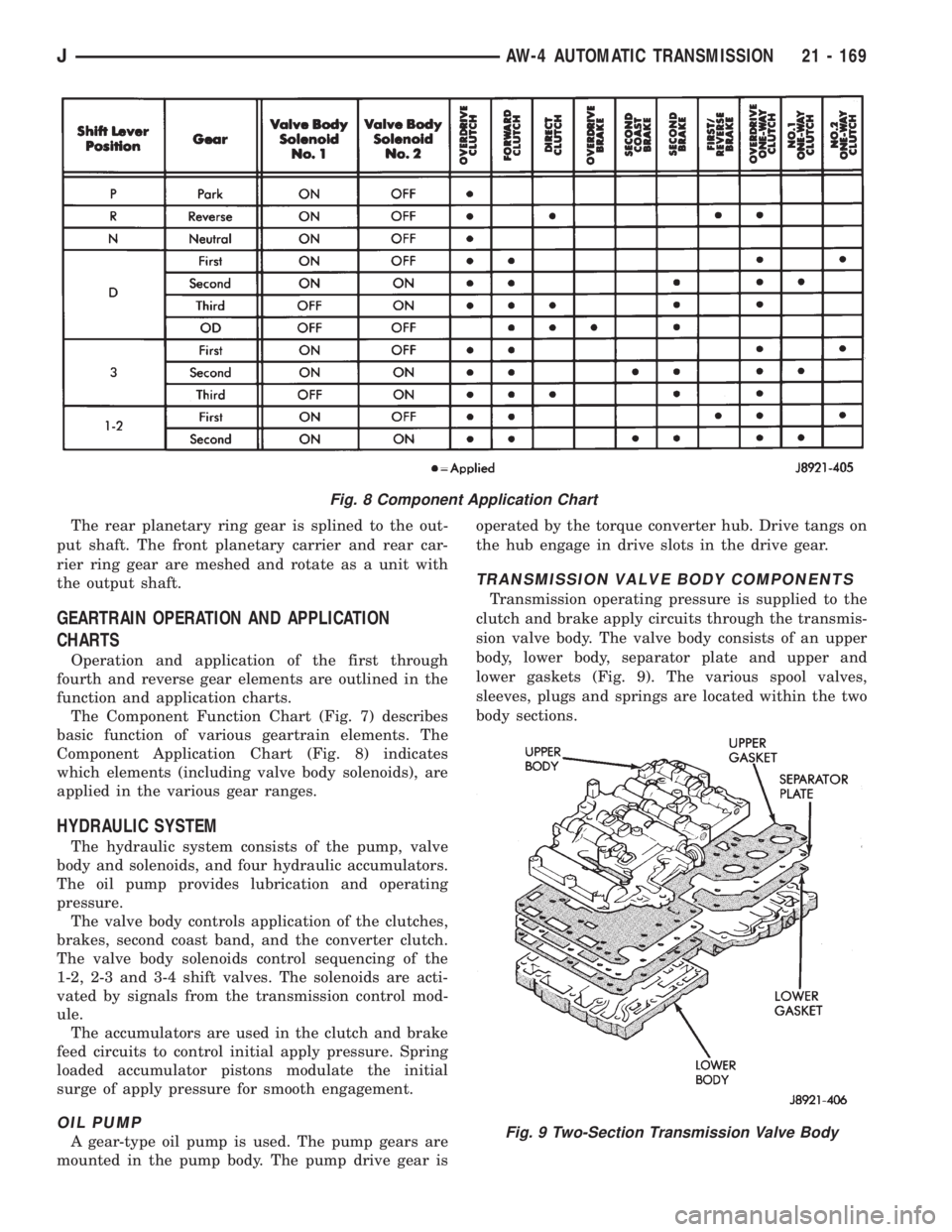
Component Application Chart (Fig. 8) indicates
which elements (including valve body solenoids), are
applied in the various gear ranges.
HYDRAULIC SYSTEM
The hydraulic system consists of the pump, valve
body and solenoids, and four hydraulic accumulators.
The oil pump provides lubrication and operating
pressure.
The valve body controls application of the clutches,
brakes, second coast band, and the converter clutch.
The valve body solenoids control sequencing of the
1-2, 2-3 and 3-4 shift valves. The solenoids are acti-
vated by signals from the transmission control mod-
ule.
The accumulators are used in the clutch and brake
feed circuits to control initial apply pressure. Spring
loaded accumulator pistons modulate the initial
surge of apply pressure for smooth engagement.
OIL PUMP
A gear-type oil pump is used. The pump gears are
mounted in the pump body. The pump drive gear isoperated by the torque converter hub. Drive tangs on
the hub engage in drive slots in the drive gear.
TRANSMISSION VALVE BODY COMPONENTS
Transmission operating pressure is supplied to the
clutch and brake apply circuits through the transmis-
sion valve body. The valve body consists of an upper
body, lower body, separator plate and upper and
lower gaskets (Fig. 9). The various spool valves,
sleeves, plugs and springs are located within the two
body sections.
Fig. 8 Component Application Chart
Fig. 9 Two-Section Transmission Valve Body
JAW-4 AUTOMATIC TRANSMISSION 21 - 169
Page 1547 of 2198
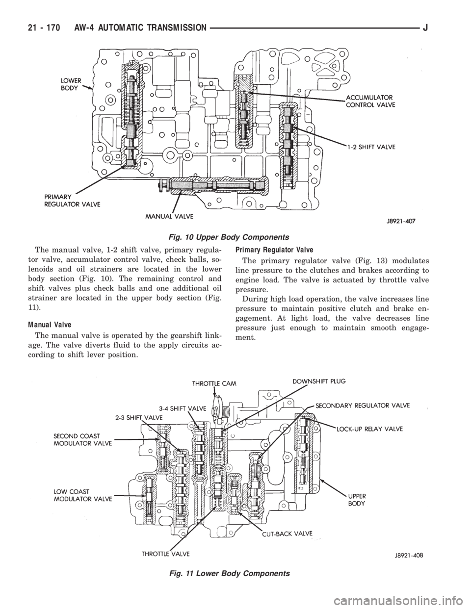
The manual valve, 1-2 shift valve, primary regula-
tor valve, accumulator control valve, check balls, so-
lenoids and oil strainers are located in the lower
body section (Fig. 10). The remaining control and
shift valves plus check balls and one additional oil
strainer are located in the upper body section (Fig.
11).
Manual Valve
The manual valve is operated by the gearshift link-
age. The valve diverts fluid to the apply circuits ac-
cording to shift lever position.Primary Regulator Valve
The primary regulator valve (Fig. 13) modulates
line pressure to the clutches and brakes according to
engine load. The valve is actuated by throttle valve
pressure.
During high load operation, the valve increases line
pressure to maintain positive clutch and brake en-
gagement. At light load, the valve decreases line
pressure just enough to maintain smooth engage-
ment.
Fig. 10 Upper Body Components
Fig. 11 Lower Body Components
21 - 170 AW-4 AUTOMATIC TRANSMISSIONJ
Page 1548 of 2198
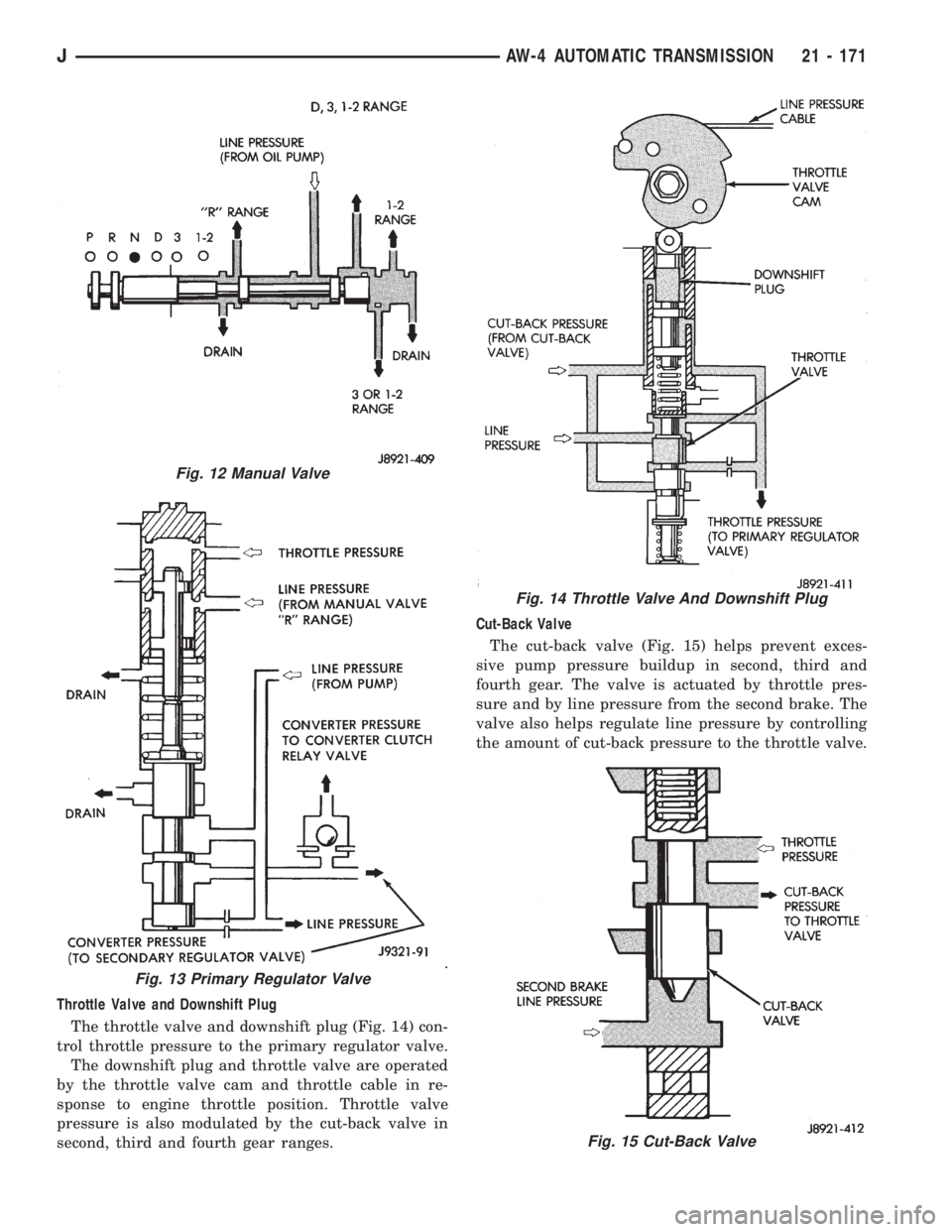
Throttle Valve and Downshift Plug
The throttle valve and downshift plug (Fig. 14) con-
trol throttle pressure to the primary regulator valve.
The downshift plug and throttle valve are operated
by the throttle valve cam and throttle cable in re-
sponse to engine throttle position. Throttle valve
pressure is also modulated by the cut-back valve in
second, third and fourth gear ranges.Cut-Back Valve
The cut-back valve (Fig. 15) helps prevent exces-
sive pump pressure buildup in second, third and
fourth gear. The valve is actuated by throttle pres-
sure and by line pressure from the second brake. The
valve also helps regulate line pressure by controlling
the amount of cut-back pressure to the throttle valve.
Fig. 12 Manual Valve
Fig. 13 Primary Regulator Valve
Fig. 14 Throttle Valve And Downshift Plug
Fig. 15 Cut-Back Valve
JAW-4 AUTOMATIC TRANSMISSION 21 - 171
Page 1549 of 2198
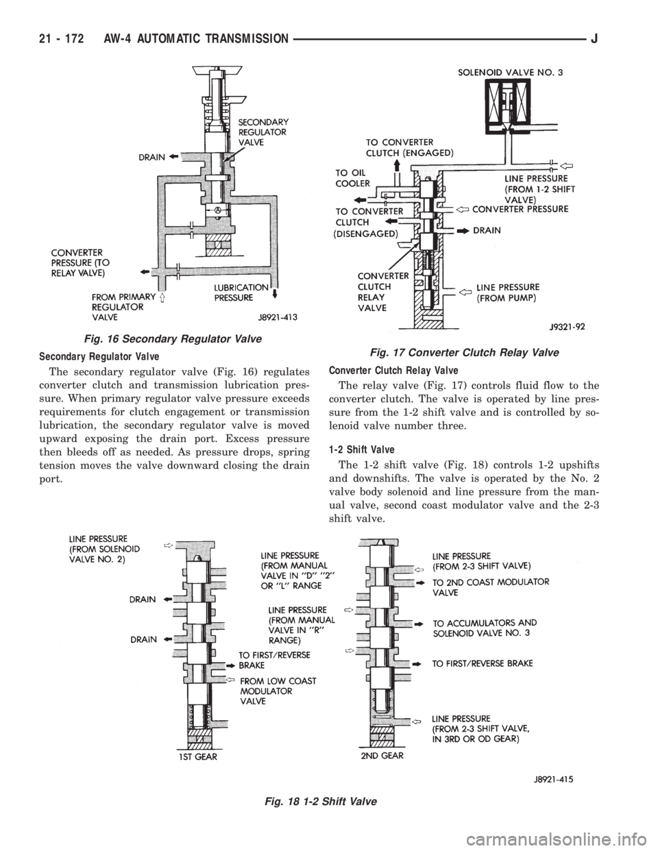
Secondary Regulator Valve
The secondary regulator valve (Fig. 16) regulates
converter clutch and transmission lubrication pres-
sure. When primary regulator valve pressure exceeds
requirements for clutch engagement or transmission
lubrication, the secondary regulator valve is moved
upward exposing the drain port. Excess pressure
then bleeds off as needed. As pressure drops, spring
tension moves the valve downward closing the drain
port.Converter Clutch Relay Valve
The relay valve (Fig. 17) controls fluid flow to the
converter clutch. The valve is operated by line pres-
sure from the 1-2 shift valve and is controlled by so-
lenoid valve number three.
1-2 Shift Valve
The 1-2 shift valve (Fig. 18) controls 1-2 upshifts
and downshifts. The valve is operated by the No. 2
valve body solenoid and line pressure from the man-
ual valve, second coast modulator valve and the 2-3
shift valve.
Fig. 16 Secondary Regulator Valve
Fig. 17 Converter Clutch Relay Valve
Fig. 18 1-2 Shift Valve
21 - 172 AW-4 AUTOMATIC TRANSMISSIONJ
Page 1550 of 2198
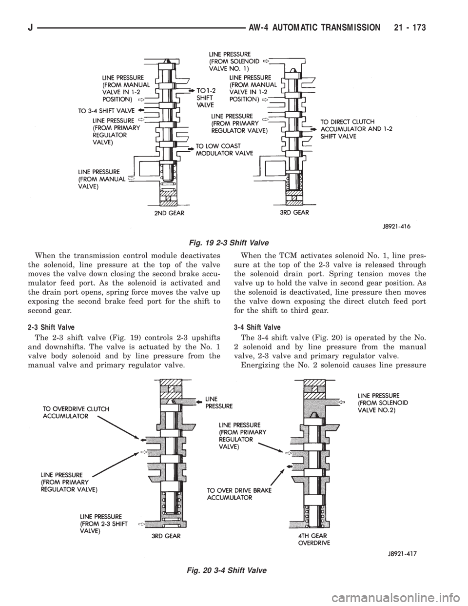
When the transmission control module deactivates
the solenoid, line pressure at the top of the valve
moves the valve down closing the second brake accu-
mulator feed port. As the solenoid is activated and
the drain port opens, spring force moves the valve up
exposing the second brake feed port for the shift to
second gear.
2-3 Shift Valve
The 2-3 shift valve (Fig. 19) controls 2-3 upshifts
and downshifts. The valve is actuated by the No. 1
valve body solenoid and by line pressure from the
manual valve and primary regulator valve.When the TCM activates solenoid No. 1, line pres-
sure at the top of the 2-3 valve is released through
the solenoid drain port. Spring tension moves the
valve up to hold the valve in second gear position. As
the solenoid is deactivated, line pressure then moves
the valve down exposing the direct clutch feed port
for the shift to third gear.
3-4 Shift Valve
The 3-4 shift valve (Fig. 20) is operated by the No.
2 solenoid and by line pressure from the manual
valve, 2-3 valve and primary regulator valve.
Energizing the No. 2 solenoid causes line pressure
Fig. 19 2-3 Shift Valve
Fig. 20 3-4 Shift Valve
JAW-4 AUTOMATIC TRANSMISSION 21 - 173
Page 1551 of 2198
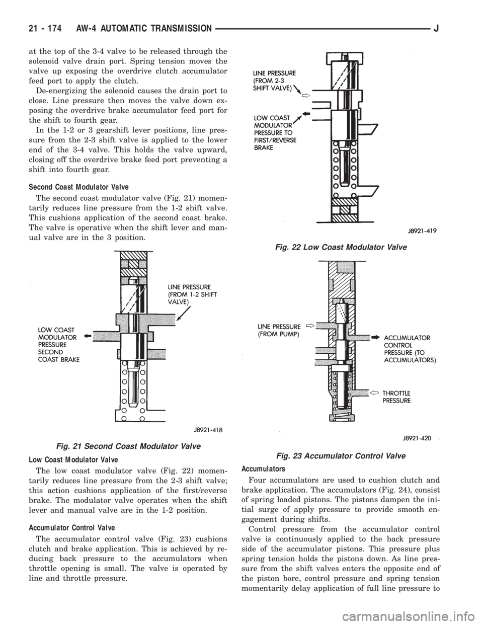
at the top of the 3-4 valve to be released through the
solenoid valve drain port. Spring tension moves the
valve up exposing the overdrive clutch accumulator
feed port to apply the clutch.
De-energizing the solenoid causes the drain port to
close. Line pressure then moves the valve down ex-
posing the overdrive brake accumulator feed port for
the shift to fourth gear.
In the 1-2 or 3 gearshift lever positions, line pres-
sure from the 2-3 shift valve is applied to the lower
end of the 3-4 valve. This holds the valve upward,
closing off the overdrive brake feed port preventing a
shift into fourth gear.
Second Coast Modulator Valve
The second coast modulator valve (Fig. 21) momen-
tarily reduces line pressure from the 1-2 shift valve.
This cushions application of the second coast brake.
The valve is operative when the shift lever and man-
ual valve are in the 3 position.
Low Coast Modulator Valve
The low coast modulator valve (Fig. 22) momen-
tarily reduces line pressure from the 2-3 shift valve;
this action cushions application of the first/reverse
brake. The modulator valve operates when the shift
lever and manual valve are in the 1-2 position.
Accumulator Control Valve
The accumulator control valve (Fig. 23) cushions
clutch and brake application. This is achieved by re-
ducing back pressure to the accumulators when
throttle opening is small. The valve is operated by
line and throttle pressure.Accumulators
Four accumulators are used to cushion clutch and
brake application. The accumulators (Fig. 24), consist
of spring loaded pistons. The pistons dampen the ini-
tial surge of apply pressure to provide smooth en-
gagement during shifts.
Control pressure from the accumulator control
valve is continuously applied to the back pressure
side of the accumulator pistons. This pressure plus
spring tension holds the pistons down. As line pres-
sure from the shift valves enters the opposite end of
the piston bore, control pressure and spring tension
momentarily delay application of full line pressure to
Fig. 21 Second Coast Modulator Valve
Fig. 22 Low Coast Modulator Valve
Fig. 23 Accumulator Control Valve
21 - 174 AW-4 AUTOMATIC TRANSMISSIONJ
Page 1552 of 2198
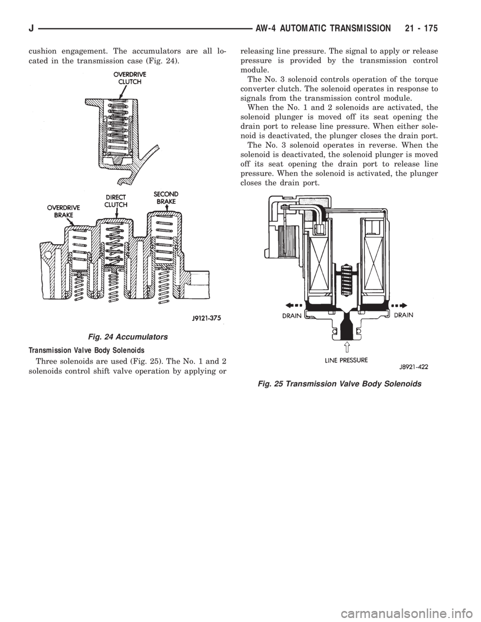
cushion engagement. The accumulators are all lo-
cated in the transmission case (Fig. 24).
Transmission Valve Body Solenoids
Three solenoids are used (Fig. 25). The No. 1 and 2
solenoids control shift valve operation by applying orreleasing line pressure. The signal to apply or release
pressure is provided by the transmission control
module.
The No. 3 solenoid controls operation of the torque
converter clutch. The solenoid operates in response to
signals from the transmission control module.
When the No. 1 and 2 solenoids are activated, the
solenoid plunger is moved off its seat opening the
drain port to release line pressure. When either sole-
noid is deactivated, the plunger closes the drain port.
The No. 3 solenoid operates in reverse. When the
solenoid is deactivated, the solenoid plunger is moved
off its seat opening the drain port to release line
pressure. When the solenoid is activated, the plunger
closes the drain port.
Fig. 24 Accumulators
Fig. 25 Transmission Valve Body Solenoids
JAW-4 AUTOMATIC TRANSMISSION 21 - 175
Page 1574 of 2198
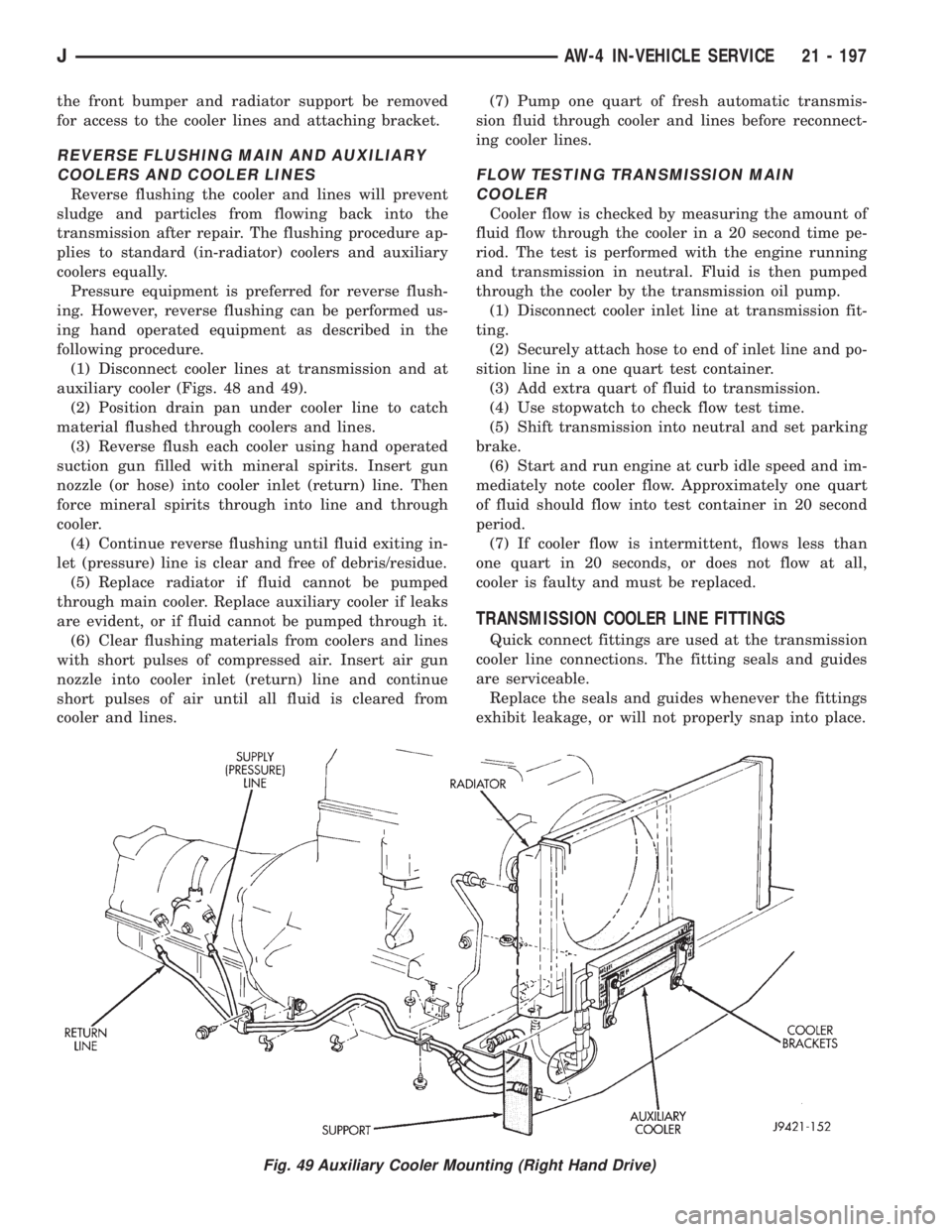
the front bumper and radiator support be removed
for access to the cooler lines and attaching bracket.
REVERSE FLUSHING MAIN AND AUXILIARY
COOLERS AND COOLER LINES
Reverse flushing the cooler and lines will prevent
sludge and particles from flowing back into the
transmission after repair. The flushing procedure ap-
plies to standard (in-radiator) coolers and auxiliary
coolers equally.
Pressure equipment is preferred for reverse flush-
ing. However, reverse flushing can be performed us-
ing hand operated equipment as described in the
following procedure.
(1) Disconnect cooler lines at transmission and at
auxiliary cooler (Figs. 48 and 49).
(2) Position drain pan under cooler line to catch
material flushed through coolers and lines.
(3) Reverse flush each cooler using hand operated
suction gun filled with mineral spirits. Insert gun
nozzle (or hose) into cooler inlet (return) line. Then
force mineral spirits through into line and through
cooler.
(4) Continue reverse flushing until fluid exiting in-
let (pressure) line is clear and free of debris/residue.
(5) Replace radiator if fluid cannot be pumped
through main cooler. Replace auxiliary cooler if leaks
are evident, or if fluid cannot be pumped through it.
(6) Clear flushing materials from coolers and lines
with short pulses of compressed air. Insert air gun
nozzle into cooler inlet (return) line and continue
short pulses of air until all fluid is cleared from
cooler and lines.(7) Pump one quart of fresh automatic transmis-
sion fluid through cooler and lines before reconnect-
ing cooler lines.
FLOW TESTING TRANSMISSION MAIN
COOLER
Cooler flow is checked by measuring the amount of
fluid flow through the cooler in a 20 second time pe-
riod. The test is performed with the engine running
and transmission in neutral. Fluid is then pumped
through the cooler by the transmission oil pump.
(1) Disconnect cooler inlet line at transmission fit-
ting.
(2) Securely attach hose to end of inlet line and po-
sition line in a one quart test container.
(3) Add extra quart of fluid to transmission.
(4) Use stopwatch to check flow test time.
(5) Shift transmission into neutral and set parking
brake.
(6) Start and run engine at curb idle speed and im-
mediately note cooler flow. Approximately one quart
of fluid should flow into test container in 20 second
period.
(7) If cooler flow is intermittent, flows less than
one quart in 20 seconds, or does not flow at all,
cooler is faulty and must be replaced.
TRANSMISSION COOLER LINE FITTINGS
Quick connect fittings are used at the transmission
cooler line connections. The fitting seals and guides
are serviceable.
Replace the seals and guides whenever the fittings
exhibit leakage, or will not properly snap into place.
Fig. 49 Auxiliary Cooler Mounting (Right Hand Drive)
JAW-4 IN-VEHICLE SERVICE 21 - 197