Page 49 of 1708

B ON-VEHICLE MAINTENANCE TIMING BELT Removal / lnstallation 1. Disconnect the negative battery cable. 2. Drain the engine coolant. 3. Remove the under cover. 4. Remove in the order shown in the figure, referring to Removal Note. 5. Install in the reverse order of removal, referring to lnstallation Note. (80-110 kgfmn, 7.9-10.7 Nm 13-17 Nm (125-175 kgfcm, 109-151 In4bf) Nm (kgfm, ft4bf) 45UOBX425 1. Air intake pipe 12. Spark plug 2. Upper radiator hose Removal / Installation ......... section G 3. Water hoses (Connected to thermostat 13. PCV valve housing) 14. Cylinder head cover 4. PIS andlor A/C drive belt 15. Upper timing belt cover Removal 1 Installation ....... page B- 6 16. Middle timing belt cover 5. Alternator drive belt 17. Lower timing belt cover Removal / Installation ....... page 5 6 18. Timing belt 6. Water pump pulley Removal Note ............. page B-13 7. Plate Installation Note ........... page B-14 8. Crankshaft pulley Inspection ................. page 8-58 9. Pulley lock bolt 19. Tensioner, tensioner spring Removal Note ............. page B-13 Installation Note ........... page B-14 /' Installation Note ........... page 51 5 Inspection ................. page 558 10. Pulley boss 20. Idler 11. Ignition coil and high-tension lead Inspection ................. page 8-58 Gartner Banana
Page 76 of 1708

DISASSEMBLY B CYLINDER HEAD Disassemble in the order shown in the figure, referring to Disassembly Note. 1. Camshaft ~ullev 9. Valve keeper .......... ~isassembl~ Note .......... page B-40 isa assembly Note page I340 Inspection ................. page B-58 10. Upper valve spring seat . - 2. camshaft 11. Valve spring ................. Disassembly Note .......... page B-40 Inspection page 6-51 Inspection ................. page B-51 1 2. Lower valve spring seat 3. HLA 13. Valve ................. Disassembly Note .......... page B-40 Inspection page 8-48 Inspection ................. page 8-53 14. Valve seal .......... 4. Seal plate Disassembly Note page B-41 5. Thermostat housing Inspect for wear or damage 6. Cylinder head bolt 15. Valve guide ................. Disassembly Note .......... page 6-40 Inspection page B-48 i/ .............. 7. Cylinder head Replacement page B-49 ................. Inspection page B-47 16. Water temperature sender unit 8. Cylinder head gasket Gartner Banana
Page 108 of 1708
ASSEMBLY Cylinder Head Gasket 1. Remove all foreign material from the top of the cylinder block. 2. Place the new cylinder head gasket in position. Cylinder Head 1. Install the cylinder head. 2. Apply clean engine oil to the bolt threads and seat faces. 3. Tighten the cylinder head bolts in two or three steps in the order shown. Tightening torque: 76-81 N-m (7.7--8.3 kgf.m, 56-60 ft4bf) Thermostat Housing 1. Remove all foreign material from the thermostat housing mounting surface. 2. Install a new O-ring and the thermostat housing. Tightening torque: 19-25 N.m (1.9-2.6 kgf.m, 14--18 ft-lbf) Seal Plate Install the seal plate on the cylinder head. Tightening torque: 7.9-10.7 N-m (80-110 kgfem, 70-95.4 in4bf) HLA 1. Apply clean engine oil to the friction surfaces. 2. If the HLA are being reused, install them in the position from which they were removed. 3. Verify that the HLA move smoothly in their bores. Gartner Banana
Page 137 of 1708

- . - . Before beginning any service procedure, refer to section T of this manual for air bag system service warnings and audio antitheft system alarm conditions . COOLING SYSTEM INDEX ....................................... E- 2 OUTLINE ..................................... E- 3 SPECIFICATIONS ........................... E- 3 TROUBLESHOOTING GUIDE .................. E- 3 ENGINE COOLANT ........................... E- 4 PREPARATION ............................. E- 4 INSPECTION ............................... E- 4 REPLACEMENT ............................ E- 5 REFILLING ................................. E- 6 .............................. RADIATOR CAP E- 7 ............................. PREPARATION E- 7 INSPECTION ............................... E- 7 RADIATOR ................................... E- 8 REMOVAL I INSTALLATION .................. E- 8 INSPECTION ............................... E- 8 THERMOSTAT ................................ E- 9 REMOVAL I INSTALLATION .................. E- 9 INSPECTION ............................... E- 9 WATER PUMP ................................ E-10 REMOVAL / INSTALLATION .................. E-10 COOLANT FAN MOTOR ....................... E-12 INSPECTION ............................... E-12 REPLACEMENT ............................ E-12 ........................ COOLANT FAN RELAY E-13 ............................... INSPECTION E-13 45UOEX-001 Gartner Banana
Page 138 of 1708
INDEX INDEX 1. Engine coolant Inspection ................... page E-4 Replacement ................ page E-5 2. Radiator cap Inspection ................... page E-7 3. Radiator Removal / Installation ......... page E-8 Inspection ................... page E-8 4. Thermostat Removal / Installation ......... page E-9 Inspection ................... page E-9 5. Water pump Removal / Installation ....... page E-10 6. Coolant fan motor Inspection ................. page E-12 Replacement .............. page E-12 7. Coolant fan relay Inspection ................. page E-13 Gartner Banana
Page 139 of 1708
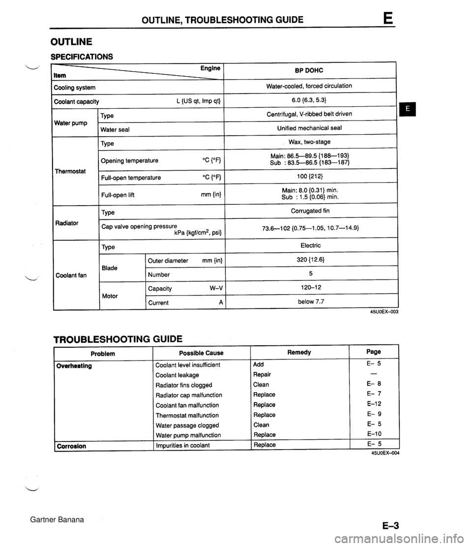
OUTLINE, TROUBLESHOOTING GUIDE OUTLINE SPECIFICATIONS Cooling system I Water-cooled, forced circulation I - - Engine Item - Water pump BP DOHC Coolant capacity L {US qt, Imp qt) TY ~e Thermostat 6.0 {6.3,5.3} Centrifugal, V-ribbed belt driven Radiator - Coolant fan Opening temperature Water seal TY pe Main: 86.5-89.5 {l 88-1 93) Sub : 83.5-86.5 (1 83-1 87) Unified mechanical seal Wax, two-stage I Full-open temperature "C ("F) 100 {212} 1 Full-open lift mm {in} Main: 8.0 (0.31) min. Sub : 1.5 (0.06) min. TY pe Corrugated fin Cap valve opening pressure kPa {kgf/cm2, psi} 1 TROUBLESHOOTING GUIDE Problem Electric 320 {l 2.6) 5 120-1 2 below 7.7 Type 45UOEX-003 Blade Motor Coolant level insufficient 1 Add Outer diameter mm {in) Number Capacity W-V Current A Possible Cause Coolant leakage 1 Repair Remedy Radiator fins clogged ( Clean Radiator cap malfunction 1 Replace Coolant fan malfunction 1 Replace Thermostat malfunction 1 Replace Water passage clogged 1 Clean Water pump malfunction Impurities in coolant Replace Replace Gartner Banana
Page 145 of 1708
THERMOSTAT E THERMOSTAT REMOVAL / INSTALLATION u 1. Disconnect the negative battery cable. 2. Drain the engine coolant. (Refer to page E-5 for WARNING and procedure.) 3. Remove in the order shown in the figure. 4. Install in the reverse order of removal. @) REPLACE TAB MUST BE ASSEMBLED TOWARD THERMOSTAT COVER 1. Thermostat cover 3. Thermostat 2. Thermostat cover gasket Inspection . . . . . . . . . . . . . . . . . . . . . . below INSPECTION 1. Visually check that the thermostat valve is airtight. 2. Place the thermostat and a thermometer in water. 3. Heat the water and check the following: Initial-opening temperature Main: 86.5-89.S°C (1 88--193OF) Sub: 83.5--86.S°C (1 8Sl87OF) Full-open temperature: 100°C (21 2°F) Full-open lift Main: 8.0mm 10.31 in) min. Sub: 1.5mm (0.06 in) min. Steps After installation 1. Connect the negative battery cable. 2. Fill the radiator with coolant. (Refer to page €4 for WARNING and procedure.) u Gartner Banana
Page 217 of 1708
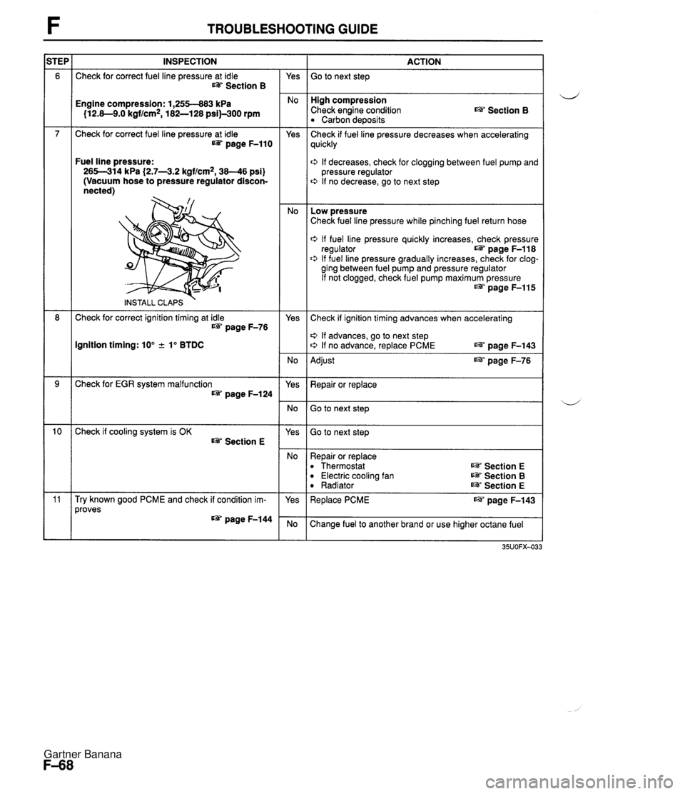
TROUBLESHOOTING GUIDE INSPECTION Check for correct fuel line pressure at idle Section B ACTION Go to next step - Yes High compression Check engine condition Carbon deposits Engine compression: 1,255-883 kPa 112.8-9.0 kgf/cm2, 182-128 psi)-300 rpm Section B Check for correct fuel line pressure at idle page F-110 Yes - No Check if fuel line pressure decreases when accelerating quickly Fuel line pressure: 265-314 kPa (2.7-43.2 kgf/cm2, 38-46 psi) (Vacuum hose to pressure regulator discon- nected) 0 If decreases, check for clogging between fuel pump and pressure regulator 0 If no decrease, go to next step Low pressure Check fuel line pressure while pinching fuel return hose 0 If fuel line pressure quickly increases, check pressure regulator page F-118 0 If fuel line pressure gradually increases, check for clog- ging between fuel pump and pressure regulator If not clogged, check fuel pump maximum pressure w page F-115 INSTALL CLAPS Check for correct ignition timing at idle IJ&T page F-76 Yes Check if ignition timing advances when accelerating o If advances, go to next step o If no advance, replace PCME LW page F-143 Ignition timing: 10" + lo BTDC No - Yes Adjust page F-76 Check for EGR system malfunction page F-124 Repair or replace Go to next step Go to next step Check if cooling system is OK Section E Yes No - Yes Repair or replace Thermostat Electric cooling fan Radiator ~3 Section E Section B Section E Try known good PCME and check if condition im- proves IJ&T page F-144 Replace PCME page F-143 Change fuel to another brand or use higher octane fuel Gartner Banana


