Page 310 of 1708

OUTLINE OUTLINE SPECIFICATIONS (i.e. powertrain control module (engine), audio, etc.) *2 With System Selector (49 B019 9AO) test switch at SELF TEST. - Engine Item Starter Ignition system Cylinder Arrangement Battery BP DOHC MT I AT 12, Negative ground S46A24L(S) (32 Ah) Maintenance-free 20.0 A.C. I REAR Voltage V Type and capacity (5-hour rate) 12-65 -. 1 2-70 Drive belt deflection mm {in} Dark current" m A Transistorized (built-in voltage regulator) 14.3-1 4.9 21.5 I0.846) 8 (0.31 1 Ignition timing** BTDC ("CA)lrpm U Alternator 'I Dark current is the constant flow of current while the ignition switch is OFF. 45UoGX-003 New Used 101850 Ignition coil Spark plug FRONT 55-7.0 (0.22-0.27) 6.0-7.5 (0.2H.29) 101800 TY pe Primary coil winding n Secondary coil winding kR Type Plug gap mm {in) Firing order Type Output V-A Regulator type Regulated voltage V TY pe Output V-kW Molded (with igniter) - 8.7-1 2.9 (20°C (68°F)) NGK : BKR5E-11 BKR6E-11 (Standard ... MT) NIPPONDENSO : K16PR-U11 K20PR-U11 (Standard ... MT, AT) 1 .O-1.1 IO.040-0.043) 1-3-4--2 Brush length mm {in) Direct 124.95 17.0 i0.67) 11.5 I0.45) Brush length mm {in} Standard Minimum Coaxial reduction 12-1.4 17.5 i0.69) 12.0 i0.47) Standard Minimum Electronic spark advance (ESA) Powertrain control module (engine) controls spark advance Type Spark advance control Gartner Banana
Page 321 of 1708

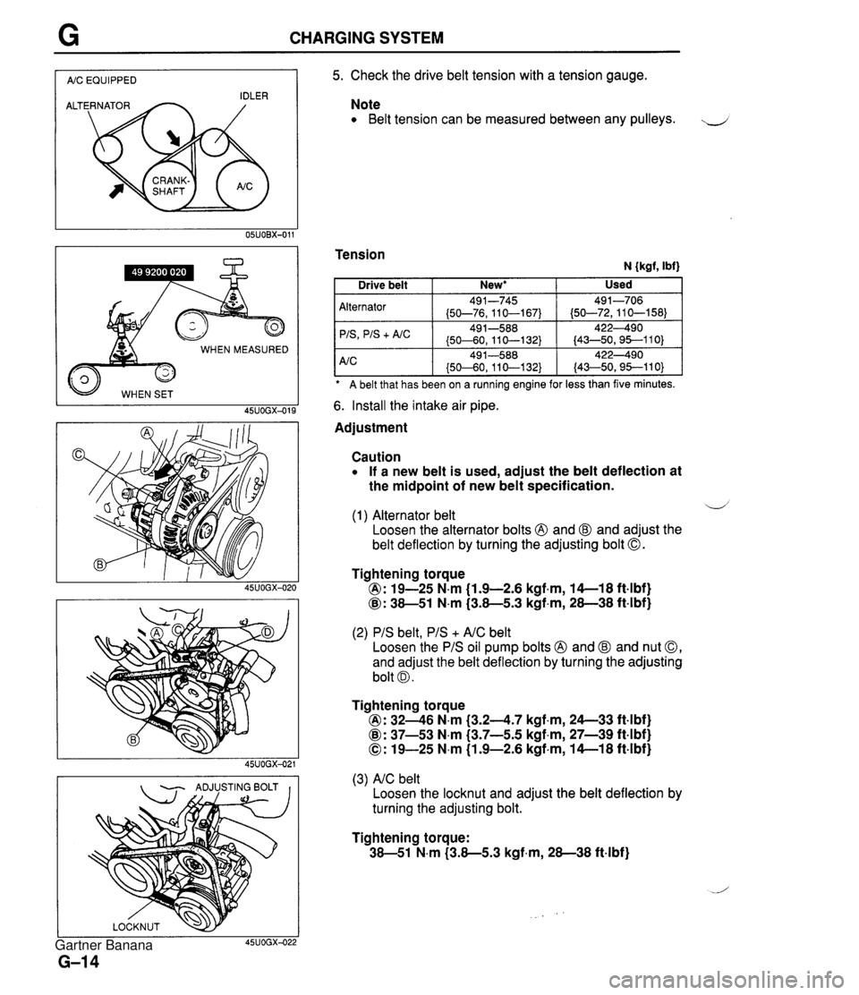
CHARGING SYSTEM I AIC EQUIPPED I WHEN MEASURED 45UOGX-015 - ADJUSTING BOLT I I 5. Check the drive belt tension with a tension gauge. Note Belt tension can be measured between any pulleys. J Tension N {kgf, Ibf) A belt that has been on a ruining engine for less than five minutes. Alternator 'IS
+ A/C 6. Install the intake air pipe. Used Drive belt Adjustment New* I Caution If a new belt is used, adjust the belt deflection at the midpoint of new belt specification. 491-745 (50-76,110-167) 49 1-588 (50-60, 11 0-1 32) d (1) Alternator belt Loosen the alternator bolts @ and @ and adjust the belt deflection by turning the adjusting bolt 0. 491-706 (50-72,110-158) 422490 (43-50,95--110) Tightening torque @: 19-25 N.m (1.9-2.6 kgf.m, 14-1 8 ft4bf) @: 38-51 N.m (3.8-5.3 kgf,m, 28-38 ft-lbf) (2) PIS belt, PIS + AIC belt Loosen the PIS oil pump bolts @ and @ and nut 0, and adjust the belt deflection by turning the adjusting bolt 0. Tightening torque @: 3246 N.m (3.24.7 kgf.m, 24--33 ft4bf) @: 37-53 N.m (3.7-5.5 kgf,m, 27-39 ft-lbf) 0: 19-25 N.m (1.9-2.6 kgf-m, 14-1 8 ft-lbf) (3) AIC belt Loosen the locknut and adjust the belt deflection by turning the adjusting bolt. Tightening torque: 38-51 N.m (3.8-5.3 kgf-m, 28-38 ft-lbf) Gartner Banana
Page 324 of 1708

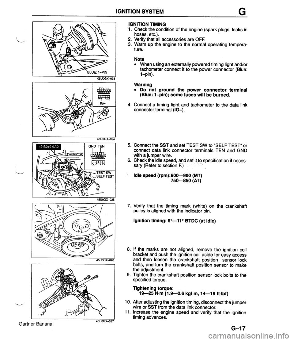
IGNITION SYSTEM G GND TEN I I I IGNITION TIMING 1. Check the condition of the engine (spark plugs, leaks in hoses, etc.). 2. Verify that all accessories are OFF. 3. Warm up the engine to the normal operating tempera- ture. Note When using an externally powered timing light and/or tachometer connect it to the power connector (Blue: l-pin). Warning Do not ground the power connector. terminal (Blue: l-pin); some fuses will be burned. 4. Connect a timing light and tachometer to the data link connector terminal (IG-). 5. Connect the SST and set TEST SW to "SELF TEST" or connect data link connector terminals TEN and GND with a jumper wire. 6. Check the idle speed, and set it to specification if neces- sary (Refer to section F.) ' Idle speed (rpm):800-900 (MT) 75-50 (AT) 7. Verify that the timing mark (white) on the crankshaft pulley is aligned with the indicator pin. Ignition timing: 9"-11" BTDC (at idle) 8. If the marks are not aligned, remove the ignition coil bracket and push the ignition coil aside for easy access and then loosen the crankshaft position sensor lock bolts, and turn the crankshaft position sensor to make the adjustment. 9. Tighten the crankshaft position sensor lock bolts to the specified torque. Tightening torque: 19-25 N-m (1 3-2.6 kgf~m, l4--19 ft.lbf) 10. After adjusting the ignition timing, disconnect the jumper wire or SST from the data link connector. 11. Increase the engine speed and verify that the ignition timing advances. Gartner Banana
Page 338 of 1708

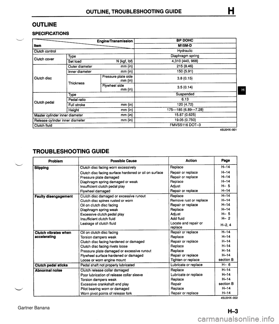
OUTLINE, TROUBLESHOOTING GUIDE H OUTLINE SPECIFICATIONS I Clutch control L' Clutch cover Clutch disc Clutch pedal - Enginerrransmission BP DOHC item - M15M-D 1 Master cvlinder inne I Hydraulic Inner diameter mm {in) I 150 (5.91) I Pressure plate side I n n rn cr Tvpe . . Set load N {kgf, Ibf) Outer diameter mm {in) Pedal ratio 6.13 Full stroke mm {in) I 120 (4.72) Diaphraam spring .-.- 4,310 (440,968) 21 5 18.46) . - Height mm {in) * diameter mm {in) TROUBLESHOOTING GUIDE . - I 75--185 i6.89--7.283 15.87 (0.625) . - Release cylinder inner diameter mm {in) Clutch fluid I Problem I Possible Cause 19.05 i0.750) FMVSS116 DOT-3 Clutch disc facing surface hardened or oil on surface Pressure plate damaged u Diaphragm spring damaged or weak lnsufficient clutch pedal play I Slipping I Clutch disc facing worn excessively I Flywheel damaged Faulty disengagement I Clutch disc damaged or excessive runout Clutch disc spines rusted or worn Oil on clutch disc facing Diaphragm spring weak Excessive clutch pedal play Insufficient clutch fluid Leakage of clutch fluid I 1 Clutch disc facing hardened or damaged Clutch vibrates when accelerating I I Clutch disc facing rivets loose Oil on clutch disc facing Torsion dampers weak Clutch pedal stlcks Abnormal noise Pressure plate damaged or excessive runout Flywheel surface hardened or damaged Loose or worn engine mount Pedal shaft not pro~erlv lubricated Clutch release collar damaged Poor lubrication of release collar sleeve Torsion dampers weak Excessive crankshaft end play I I Pilot bearing worn or damaged I I Worn ~ivot points of release fork Action Replace Repair or replace Repair or replace Replace Adjust ~ebair or replace Replace Remove rust or replace Repair or replace Replace Adjust Add fluid Locate and repair or replace Repair or replace Replace Repair or replace Replace Replace Repair or replace Tighten or replace Lubricate or replace Replace Lubricate or replace Replace Repair Replace Repair or replace Page H-14 H-14 H-14 H-14 H-14 H-14 section B H- 6 H-14 H-14 H-14 section B H-14 H-14 45UOHX-OC Gartner Banana
Page 399 of 1708
TRANSMISSION J INSTALLATION 1. On level ground, jack up the vehicle and support it evenly on safety stands. 2. Install in the order shown in the figure, referring to lnstallation Note. L 3. Add the specified amount of the specified transmission oil. (Refer to page J-8.) 4. Warm up the engine and transmission, and inspect for oil leakage and transmission problems. 1. Transmission 7. Exhaust pipe Installation Note ............. page J-46 8. Performance rod 2. Power plant frame (PPF) 9. Differential mounting pipe Installation Note ............. page J-46 10. Undercover 3. S~eedometer cable 11. Shift lever w 4. ~iarter Installation Note ............. page J-47 5. Clutch release cylinder 12. Rear console 6. Propeller shaft 13. Shift lever knob Service ...................... section L Gartner Banana
Page 400 of 1708

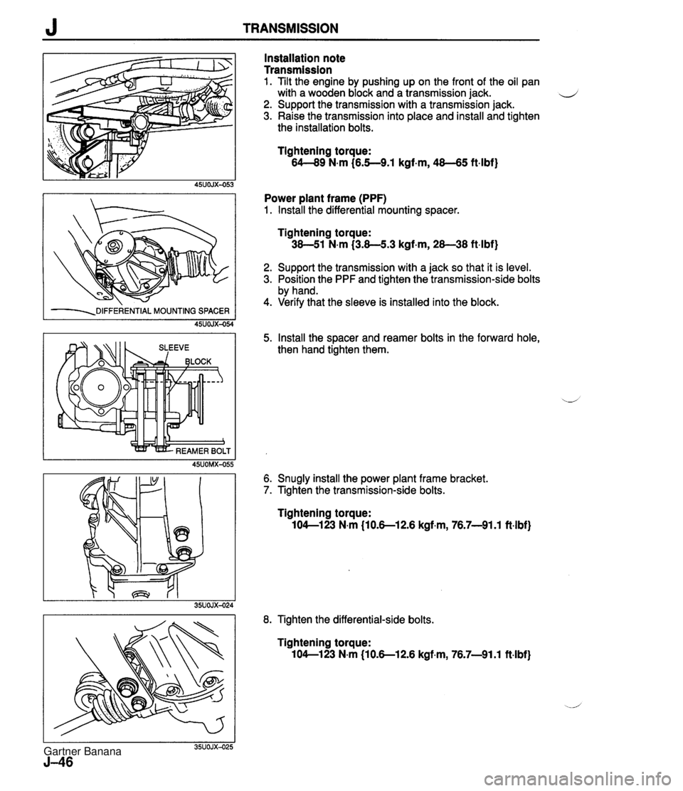
J TRANSMISSION -=DIFFERENTIAL MOUNTING SPACER 45UOJX-054 Installation note Transmission 1. Tilt the engine by pushing up on the front of the oil pan with a wooden block and a transmission jack. d 2. Support the transmission with a transmission jack. 3. Raise the transmission into place and install and tighten the installation bolts. Tightening torque: 64-89 N-m (6.5--9.1 kgf-m, 48-65 ft.lbf) Power plant frame (PPF) 1. Install the differential mounting spacer. Tightening torque: 38-51 N.m (3.8-5.3 kgf-m, 28-38 ft-lbf) 2. Support the transmission with a jack so that it is level. 3. Position the PPF and tighten the transmission-side bolts by hand. 4. Verify that the sleeve is installed into the block. 5. Install the spacer and reamer bolts in the forward hole, then hand tighten them. 6. Snugly install the power plant frame bracket. 7. Tighten the transmission-side bolts. Tightening torque: 104-123 N-m (10.S12.6 kgf.m, 76.7-91.1 ft.lbf) 8. Tighten the differential-side bolts. Tightening torque: 104-1 23 N-m (1 0.S12.6 kgf.m, 76.7-91.1 ft-lbf) Gartner Banana
Page 410 of 1708

TROUBLESHOOTING If the 3 steps on page K-8 are followed, the cause of the problem should be located. Another guide to faster location of the causes of problems, the QUICK DIAGNOSIS CHART, is on page K-1 0. b In this chart, numbers are used to indicate the components that may be the cause of 22 possible prob- lems. It is necessary to check only those components indicated by numbers during each step of the trouble- shooting process to locate the cause of the problem quickly. QUICK DIAGNOSIS CHART The QUICK DIAGNOSIS CHART shows different .problems and the relationship of components that might be the cause. 1. Components indicated in the "Adjustment" row indicate the possibility that the problem may result from an incorrect adjustment. Check the adjustment of each component, and readjust if necessary. 2. Components indicated in the "Self-DiagnosisWrow are diagnosed by the Powertrain control module (Transmission) self-diagnostic function. 3. Input and output signals of the Powertrain control module (Transmission) for components indicated in the "Tester" row can be easily checked with the Engine signal Monitor. 4. Components indicated in the "Mechanical System Test" row can be checked for malfunction by the re- sults of oil pressure test. 5. Components indicated in the "Road Test" row can be checked for malfunction by the results of the road test. 6. The numbers in the chart indicate the order of inspection for detecting malfunctions. 7. Circled numbers indicate that the transmission must be removed from the vehicle. 8. The checking, adjusting, repair, and replacement procedures for components are described in the page(s) shown in the "Reference page" row. Gartner Banana
Page 423 of 1708
K MECHANICAL SYSTEM TEST MECHANICAL SYSTEM TEST PREPARATION SST STALL TEST 49 0378 400A Gauge set, oil pressure 49 801 9 901 Gauge, oil pressure For oil pressure test For oil pressure test This test is performed to determine if there is slippage of the friction elements or malfunction of the hy- draulic components. Preparation 1. Check the engine coolant, engine oil, and ATF levels before testing. 2. Warm the engine thoroughly to raise the ATF temperature to operating level (50--80°C, 122-176°F). 3. Engage the parking brake and use wheel chocks at the front and rear of the wheels. ENGAGE PARKING BRAKE WARM UP ENGINE COOLANT LEVEL ENGINE OIL LEVEL TEMPERATURE 60-70°C (1 40-1 58°F) ATF LEVEL Gartner Banana