1994 MAZDA MX-5 sensor
[x] Cancel search: sensorPage 291 of 1708

CONTROL SYSTEM STRUCTURAL VIEW i 1. Powertrain control module (engine) 6. Heated oxygen sensor Inspection . . . . . . . . . . . . . . . . . . page F-144 Inspection . . . . . . . . . . . . . . . . . . page F-156 Removal / Installation . . . . . . . . page F-143 Replacement . . . . . . . . . . . . . . . page F-156 2. Crankshaft position sensor 7. Main relay Removal . . . . . . . . . . . . . . . . . . . page F-153 Inspection . . . . . . . . . . . . . . . . . . page F-156 lnspection . . . . . . . . . . . . . . . . . . page F-153 8. Clutch switch Installation . . . . . . . . . . . . . . . . . page F-153 Inspection . . . . . . . . . . . . . . . . . . page F-157 3. Mass airflow sensor Replacement . . . . . . . . . . . . . . . page F-157 System inspection . . . . . . . . . . . page F-152 9. Neutral switch Inspection . . . . . . . . . . . . . . . . . . page F-152 Inspection . , . . . . . . . . . . . . . . . . page F-157 4. Engine coolant temperature sensor Replacement . . . . . . . . . . . . . . . page F-157 Removal . . . . . . . . . . . . . . . . . . . page F-154 10. Steering pressure sensor Inspection . . . . . . . . . . . . . . . . . . page F-154 Inspection . . . . . . . . . . . . . . . . . . page F-158 Installation . . . , . . . . . . . . . . . . . page F-154 Replacement . . . . . . . . . . . . . . . page F-158 5. Throttle position sensor -,' Inspection . . . . . . . . . . . . . . . . . . page F-155 Adjustment . . . . . . . . . . . . . . . . . page F-155 Replacement . . . . . . . . . . . . . . . page F-156 Gartner Banana
Page 294 of 1708

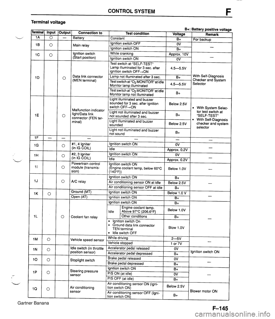
CONTROL SYSTEM F Terminal voltage B+: Battery positive voltage Test condition I Voltage I Remark - - - - - - - - - - - - - - - - - - Connection to Battery Constant Ignition switch OFF Main relay - B+ OV lgnition switch (Start position) For backup - Ignition switch ON While cranking Lamp illuminated for 3 sec. after 1 4.5-5.5V ianition switch OFF+ON 1 B+ Approx. 1 OV Ignition switch ON - - OV Data link connector (MEN terminal) Test switch at "SELF-TEST" .. Lamp not illuminated after 3 sec. Test switch at "02 MONITOR" at idle Monitor lam illuminated & 4.5-5.5v . . I Malfunction indicator IighVData link connector (FEN ter- minal) With Self-Diagnosis Checker and System Selector Test switch at "02 MONITOR" at idle Monitor lamp not illuminated Light illuminated and buzzer sounded for 3 sec. after ignition switch OFF-ON B+ tor tesiswitch at "SELF-TEST" With Self-Diagnosis checker and system selector Below 2.5V 1 Light illuminated and buzzer sounded 1 Below 2.5V I With System Selec- Light not illuminated and buzzer not sounded after 3 sec. I Light not illuminated and buzzer 1 n. 1 B+ not sound I D+ 1 - #I, 4 lgniter (in IG COIL) #2,3 Igniter (in IG COIL) Powertrain control module (transmis- sion) - Ignition switch ON Idle Ignition switch ON Idle lgnition switch ON (Engine coolant temp, below 60°C {I 40°F)) Ignition switch ON AtC relay Air conditioning sensor ON at idle Air conditioning sensor OFF at idle Ground (MT) - OV Approx. 0.2V OV Approx. 0.2V Below 1 .OV B+ Below 2.5V B+ - - - - , * Open (AT) - Ignition switch ON ( Below 1 .O V I Engine coolant temp. I Below .OV I ldle Above 97°C (206.6OF1 Ignition switch ON I I B+ Ignition switch ON Coolant fan relay B+ . - Other conditions lgnition switch On dround data link connector TEN terminal I Blow 1.0" I B+ Vehicle speed sensor ldle switch OFF While driving Vehicle sto~wed ldle switch (in throttle position sensor) 2-5V 1 or 7V . , Accelerator pedal released Accelerator ~edal de~ressed - Stoplight switch OV B+ Brake pedal released Brake ~edal deoressed lgnition switch ON Steering pressure sensor OV B+ I I - Ignition switch ON B+ - PIS ON (at idle) PIS OFF (at idle) Air conditioning sensor Air conditioning sensor ON (Igni- tion switch ON) Air conditioning sensor OFF (Igni- tion switch ON) OV B+ - Below 2.5V B+ Blower motor ON Gartner Banana
Page 295 of 1708

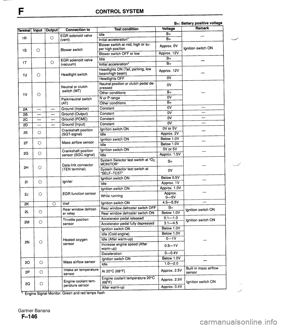
F CONTROL SYSTEM B+: Battery positive voltage Connection to 1 Test condition 1 Voltage I Remark I -- EGR solenoid valvi Idle B+ Blower switch -- EGR solenoid valve (vacuum) :vent) Initial acceleration* Blower switch at mid, high or su- per high position Blower switch OFF or low Headlight switch Neutral or clutch switch (MT) B+ Idle ParWneutral switch (AT) Ground (Injector) Ground (Output) Ground (PCME) Approx. OV - Approx. 12V B+ Headlights ON (Tail, parking, low beamfhigh beam) Headlights OFF Neutral position or clutch pedal de- pressed Other conditions Ground (Input) Crankshaft position (SGT-signal) Ignition switch ON N or fJ range Other conditions Constant Constant Constant -. Mass airflow sensor .. . . EGR function sensor I while running Approx. 0-5v Initial acceleration* Approx, 2V OV ov B+ Constant Ignition switch ON Idle Crankshaft position sensor (SGC-signal) Data link connector (TEN terminal) Igniter I I I Vre f I lanition switch ON 1 4.5-5.9.' 1 - B+ - OV B+ OV OV OV Ignition switch ON Idle - - - OV OV or 5V ADD~OX. 2V - - Ignition switch ON Idle System Selector test switch at "02 MONITOR" System Selector test switch at "SELF-TEST" Ignition switch ON Idle lanition switch ON I . . I I 1 Ignition switch ON I Below 1 .OV I I - - . . Below 1 .OV Below 1 .OV ear window defrost- er relay Throttle position sensor Heated oxygen sensor - OV or 5V Approx. 1.5V B+ ov Below 0.5V Approx. 1 V Approx. 1 .OV - - - " Rear window defroster switch OFF Rear window defroster switch ON Accelerator pedal released Accelerator ~edal fullv de~ressed Mass airflow sensor B+ Below 1 .OV 0.1-1 .o 3.14.5 Intake air temperature sensor Engine coolant tem- perature sensor lgnition switch ON lgnition switch ON Ignition switch ON Idle ireen and red lamps flash At 200C {680Fj Engine coolant temperature 20°C {680F) After warm-up Below 1 .OV 1 .O-2.0 - Approx. 2.5V Approx. 2.5V Approx. 0.4V Built in mass airflow lgnition switch ON Gartner Banana
Page 297 of 1708

CONTROL SYSTEM Check Point for Each Terminal B+: Battery positive voltage Terminal -. - Connection to Abnormal voltage Possible cause Battery Always OV (Battery OK) Always OV Main relay a ROOM 10A fuse burned Open circuit in wiring from ROOM 1 OA fuse to PCME terminal 1A Main relay malfunction (Refer to page F-156) Open circuit in wiring from main relay to PCME termi- nal 1 B Ignition switch (Start position) a Main relay malfunction (Refer to page F-156) Open circuit in wiring from main relay to data link connector terminal +B Open or short circuit in wiring from data link connec- tor terminal MEN to PCME terminal 1 D Always OV (Starter turns) Always OV Open circuit in wiring from starter interlock switch to PCME terminal 1 C Self-Diagnosis Checker (Monitor lamp) Always B+ a Poor connection at PCME connector PCME malfunction I Always approx. 5V I a PCME malfunction Malfunction indicator light (MIL) Always below 2.5V (MIL always ON) Always below 2.5V Open circuit in wiring from combination meter to (MIL never ON) I PCME terminal I E a Short circuit in wiring from combination meter to PCME terminal 1 E PCME malfunction Always B+ Poor connection at PCME connector a PCME malfunction Self-Diagnosis Checker (Code No.) Always below 2.5V (No display on Self-Diagnosis Checker) Main relay malfunction (Refer to page F-156) a Open circuit in wiring from main relay to data link connector terminal +B Always B+ Always below 2.5V ("88" is displayed and buzzer sounds continuously) a Poor connection at PCME connector a PCME malfunction - Open or short circuit in wiring from data link connec- tor terminal FEN to PCME terminal I E Igniter Always OV a Refer to Code No.01 troubleshooting I (Refer to section GI Powertrain control module (transmission) Always B+ I PCME malfunction A/C relay malfunction (Refer to section U) a Open circuit in wiring from main relay to NC relay a Open circuit in wiring from NC relay to PCME termi- nal 1 J a Short circuit in wiring from NC relay to PCME termi- nal 1 J a PCME malfunction Always below 2.5V (NC does not operate) Always below 2.5V (Air conditioning sensor OFF but A/C operates) AIC relay Air conditioning sensor malfunction (Refer to section U) Poor connection at PCME connector PCME malfunction Always B+ Open circuit in wiring from PCME terminal 1 K to ground PCME malfunction Ground (MT) Always B+ Open (AT) Always OV Short circuit in wiring from PCME terminal 1 K to grounc PCME malfunction Coolant fan relay Always below 1 .OV (Coolant fan OK) Open or short circuit in wiring from fan relay to PCME terminal I L PCME malfunction Gartner Banana
Page 298 of 1708

CONTROL SYSTEM B+: Battery positive voltage Terminal 1 M 7 1 N 10 1 P 1 Q 1 R 1 S 1 T 1 U Connection to Abnormal voltage Always approx. 1 V Always approx. 7V Possible cause r Vehicle speed sensor malfunction r Short circuit in wiring from vehicle speed sensor to PCME terminal 1 M Vehicle speed sensor - r Vehicle speed senso~malfunction r Open circuit in wiring from vehicle speed sensor to PCME terminal 1 M r Throttle position sensor misadjustment (Refer to page F-154) r Short circuit in wiring from PCME terminal 1 N to throttle position sensor 6 PCME malfunction Always OV Throttle position sensor (idle terminal) Always B+ r Throttle position sensor misadjustment (Refer to page F-154) r Open circuit in wiring from PCME terminal 1 N to throttle position sensor r Open circuit in wiring from throttle position sensor to ground Stoplight switch Always OV (Stoplights OK) r Open circuit in wiring from stoplight switch to PCME terminal 10 r Steering pressure sensor malfunction (Refer to page F-158) Short circuit in wiring from PCME terminal 1 P to steering pressure sensor r PCME malfunction r Steering pressure sensor malfunction (Refer to F-158) r Open circuit in wiring from PCME terminal 1 P to steering pressure sensor Open circuit in wiring from steering pressure sensor to ground r Air conditioning sensor malfunction (Refer to section U) r Short circuit in wiring from PCME terminal 1 Q to air conditioning sensor r Poor connection at PCME connector r PCME malfunction Always OV Steering pressure sensor Always B+ -- Air conditioning sensor Always OV (with blower switch ON) Air conditioning sensor malfunction (Refer to section U) Open circuit in wiring from PCME terminal 1Q to air conditioning sensor Open circuit in wiring from air conditioning sensor to blower switch Always B+ (with blower switch ON) (Blower fan OK) EGR solenoid valve (vent) Always OV r Refer to Code No.29 Troubleshooting (Refer to page F-92) Short circuit in wiring from blower switch to PCME terminal 1 S r Poor connection at PCME connector PCME malfunction Always OV (Blower fan OK) Blower switch Always B+ (Blower fan OK) Open circuit in wiring from blower switch to PCME terminal IS EGR solenoid (vacu- um) Always OV r Refer to Code No.28 Troubleshooting (Refer to paae F-92) Headlight switch Always OV (Headlights OK) r Open or short circuit in wiring from headlight relay to PCME terminal 1 U Gartner Banana
Page 299 of 1708

F CONTROL SYSTEM B+: Battery positive voltage Abnormal voltage Possible cause Terminal 1 v Connection to Neutral switch malfunction (Refer to page F-157) Clutch switch malfunction (Refer to page F-156) Short circuit in wiring from PCME terminal 1 V to neutral or clutch switch Neutral switch malfunction (Refer to page F-157) 0 Clutch switch malfunction (Refer to page F-156) 0 Open circuit in wiring from PCME terminal 1 V to neutral or clutch switch Poor connection at PCME connector 0 ParWneutral switch malfunction (Refer to section K) 0 Short circuit in wiring from parWneutral switch to PCME terminal 1V 0 ParWneutral switch malfunction (Refer to section K) 0 Open circuit in wiring from parWneutral switch to PCME terminal 1 V Always OV Neutral switchlClutch switch (MT) Always B+ Always OV ParWneutral switch (AT) Always B+ Poor contact at ground terminal 0 Open circuit in wiring from PCME to ground Sround More than OV Crankshaft position sensor (SGT-signal) Always OV or approx. 5V Always below 2V or 4V Refer to Code No.03 troubleshooting (Refer to page F-84) Refer to code No.08 Troubleshooting (Refer to page F-86) 0 Short circuit in wiring from PCME terminal 2H to data link connector terminal TEN Mass airflow sensor Always OV Data link connector (Terminal TEN) 0 Open circuit in wiring from PCME terminal 2H data link connector terminal TEN 0 Open circuit in wiring from data link connector terminal GND to around Always B+ Igniter EGR function sensor Always OV Always approx. OV or approx. 5v Refer to Code No.01 troubleshooting (Refer to paae F-83) 0 Refer to Code No.16 Troubleshooting (Refer to page F-89) 0 Short circuit in wiring from PCME terminal 2K tothrottle position sensor, PCME, or mass airflow sensor Poor connection at PCME connector PCME malfunction Vre f Always OV lllumination light ON when rear window defroster switch ON Open or short circuit in wiring from rear window de- froster switch to PCME terminal 2L Always below 1 .ov Rear window defroster switch Open circuit in wiring from ignition switch to rear win- dow defroster switch Rear window defroster switch malfunction (Refer to section T) lllumination light never ON Open circuit in wiring from PCME terminal 2M to throttle position sensor 0 Open circuit in wiring from PCME terminal 2K to throttle position sensor 0 Open circuit in wiring from PCME terminal 20 to throttle position sensor Always constant Throttle position sensor Alwavs above 1V 0 Throttle position sensor misadjustment Refer to Code No.15 troubleshooting (Refer to page F-88) OV after warm-up Heated oxygen sensor Always approx, 1V after warm-up 0 Refer to Code No.17 troubleshooting (Refer to page F-90) Refer to Code No.08 troubleshooting (Refer to page F-86) Mass airflow sensor Always OV or approx. 5V Gartner Banana
Page 300 of 1708

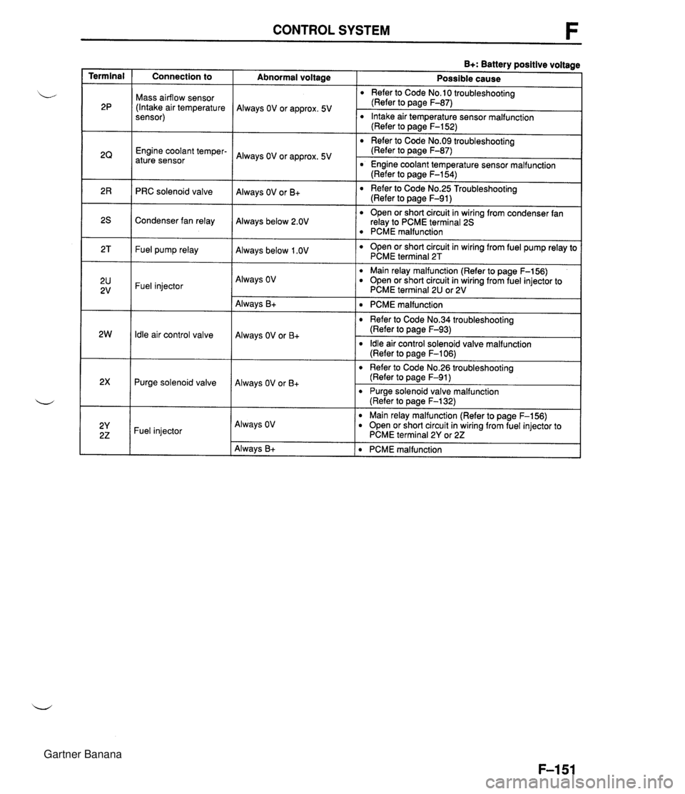
CONTROL SYSTEM B+: Battery positive voltage Terminal Connection to Abnormal voltaae Possible cause Mass airflow sensor (Intake air temperature sensor) Refer to Code No.10 troubleshooting (Refer to page F-87) Always OV or approx. 5V Intake air temperature sensor malfunction (Refer to page F-152) Refer to Code No.09 troubleshooting (Refer to page F-87) Engine coolant temper- ature sensor Always OV or approx. 5V r Engine coolant temperature sensor malfunction (Refer to page F-154) Refer to Code No.25 Troubleshooting (Refer to page F-91) Always OV or B+ PRC solenoid valve r Open or short circuit in wiring from condenser fan relay to PCME terminal 25 PCME malfunction Open or short circuit in wiring from fuel pump relay to PCME terminal 2T Condenser fan relay Always below 2.OV Fuel pump relay Always below 1 .OV Main relay malfunction (Refer to page F-156) r Open or short circuit in wiring from fuel injector to PCME terminal 2U or 2V Always OV Fuel injector ldle air control valve Purge solenoid valve Always B+ Always OV or B+ Always OV or B+ PCME malfunction r Refer to Code No.34 troubleshooting (Refer to page F-93) ldle air control solenoid valve malfunction (Refer to page F-I 06) r Refer to Code No.26 troubleshooting (Refer to page F-91) r Purge solenoid valve malfunction (Refer to pane F-132) -- Fuel injector Always OV Main relay malfunction (Refer to page F-156) Open or short circuit in wiring from fuel injector to PCME terminal 2Y or 22 Always B+ PCME malfunction Gartner Banana
Page 301 of 1708

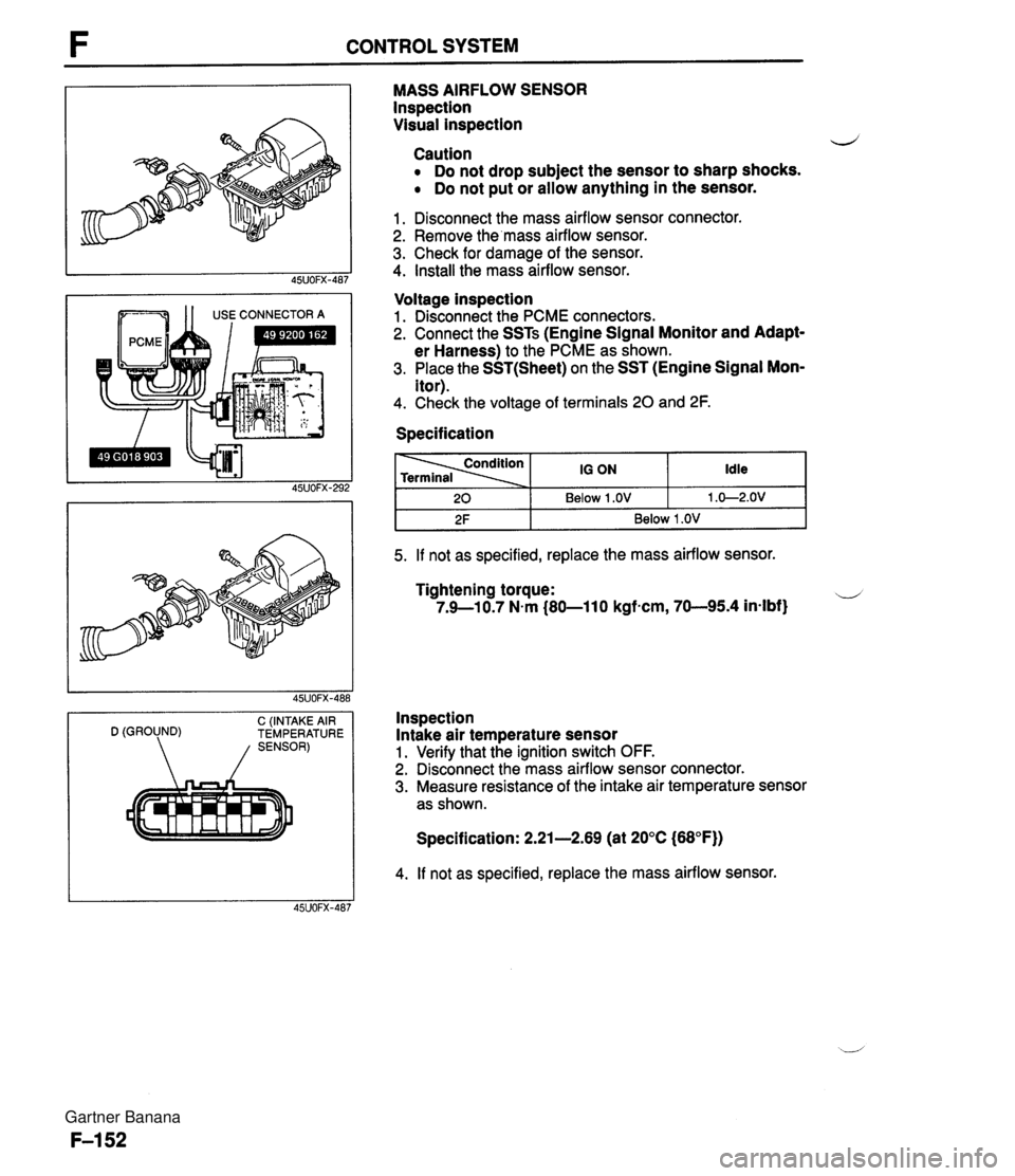
CONTROL SYSTEM --- 1 1 USE CONNECTOR A C (INTAKE AIR D (GROUND) TEMPERATURE MASS AIRFLOW SENSOR lnspection Visual inspection d Caution Do not drop subject the sensor to sharp shocks. Do not put or allow anything in the sensor. 1. Disconnect the mass airflow sensor connector. 2. Remove the'mass airflow sensor. 3. Check for damage of the sensor. 4. Install the mass airflow sensor. Voltage inspection 1. Disconnect the PCME connectors. 2. Connect the SSTs (Engine Signal Monitor and Adapt- er Harness) to the PCME as shown. 3. Place the SST(Sheet) on the SST (Engine Signal Mon- itor). 4. Check the voltage of terminals 20 and 2F. Specification I 2F I Below 1 .OV I 5. If not as specified, replace the mass airflow sensor. Idle 1 .O-2.OV 20 Tightening torque: u 7.9--10.7 N.m (80-11 0 kgfncm, 70-95.4 in-lbf} 10 ON Below 1 .OV Inspection Intake air temperature sensor 1. Verify that the ignition switch OFF. 2. Disconnect the mass airflow sensor connector. 3. Measure resistance of the intake air temperature sensor as shown. Specification: 2.21-2.69 (at 20°C (68°F)) 4. If not as specified, replace the mass airflow sensor. Gartner Banana