1994 MAZDA MX-5 sensor
[x] Cancel search: sensorPage 324 of 1708

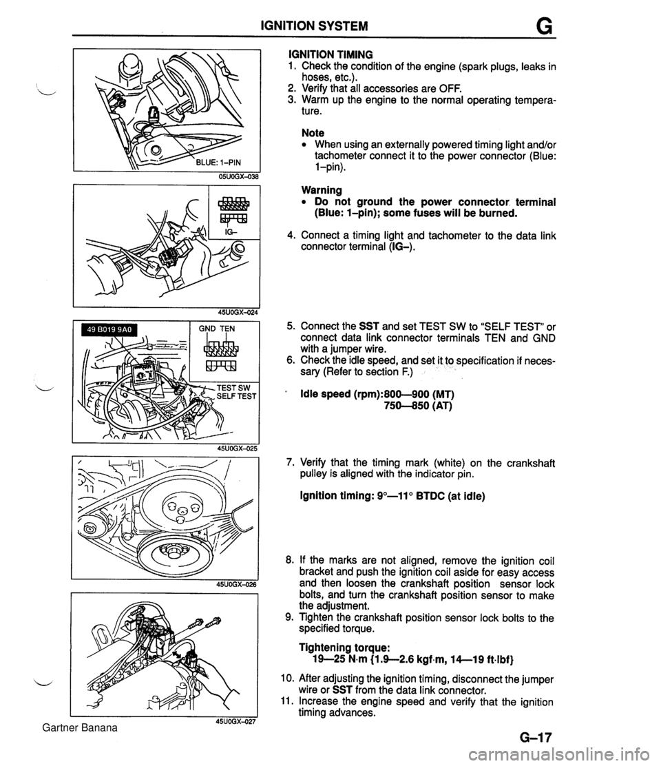
IGNITION SYSTEM G GND TEN I I I IGNITION TIMING 1. Check the condition of the engine (spark plugs, leaks in hoses, etc.). 2. Verify that all accessories are OFF. 3. Warm up the engine to the normal operating tempera- ture. Note When using an externally powered timing light and/or tachometer connect it to the power connector (Blue: l-pin). Warning Do not ground the power connector. terminal (Blue: l-pin); some fuses will be burned. 4. Connect a timing light and tachometer to the data link connector terminal (IG-). 5. Connect the SST and set TEST SW to "SELF TEST" or connect data link connector terminals TEN and GND with a jumper wire. 6. Check the idle speed, and set it to specification if neces- sary (Refer to section F.) ' Idle speed (rpm):800-900 (MT) 75-50 (AT) 7. Verify that the timing mark (white) on the crankshaft pulley is aligned with the indicator pin. Ignition timing: 9"-11" BTDC (at idle) 8. If the marks are not aligned, remove the ignition coil bracket and push the ignition coil aside for easy access and then loosen the crankshaft position sensor lock bolts, and turn the crankshaft position sensor to make the adjustment. 9. Tighten the crankshaft position sensor lock bolts to the specified torque. Tightening torque: 19-25 N-m (1 3-2.6 kgf~m, l4--19 ft.lbf) 10. After adjusting the ignition timing, disconnect the jumper wire or SST from the data link connector. 11. Increase the engine speed and verify that the ignition timing advances. Gartner Banana
Page 326 of 1708

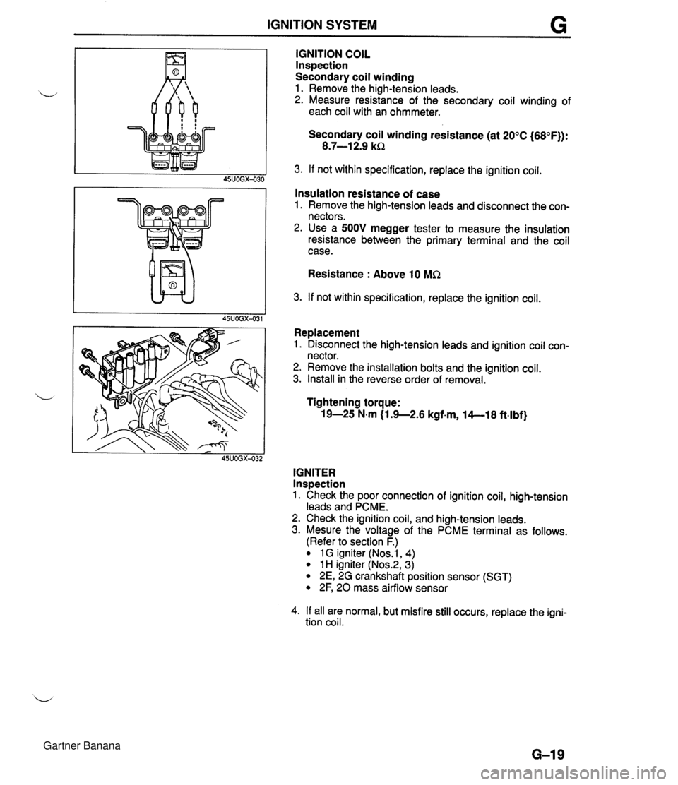
IGNITION SYSTEM IGNITION COIL lnspection Secondary coil winding 1. Remove the high-tension leads. u 2. Measure resistance of the secondary coil winding of each coil with an ohmmeter. Secondary coil winding resistance (at 20°C (68°F)): 8.7-1 2.9 kR 3. If not within specification, replace the ignition coil. 45UOGX-030 I I Insulation resistance of case 1. Remove the high-tension leads and disconnect the con- nectors. 2. Use a 500V megger tester to measure the insulation resistance between the primary terminal and the coil case. Resistance : Above 10 MR 3. If not within specification, replace the ignition coil. L I 45UOGX-031 Replacement 1. Disconnect the high-tension leads and ignition coil con- nector. 2. Remove the installation bolts and the ignition coil. 3. Install in the reverse order of removal. L Tightening torque: 19-25 N.m (1.9--2.6 kgf-m, 14--18 ft-lbf) 45UOGX-032 IGNITER Inspection 1. Check the poor connection of ignition coil, high-tension leads and PCME. 2. Check the ignition coil, and high-tension leads. 3. Mesure the voltage of the PCME terminal as follows. (Refer to section F.) 1 G igniter (Nos.1, 4) 1 H igniter (Nos.2, 3) 2E, 2G crankshaft position sensor (SGT) 2F, 20 mass airflow sensor 4. If all are normal, but misfire still occurs, replace the igni- tion coil. Gartner Banana
Page 366 of 1708

J TRANSMISSION Caution Removing the PPF spacers will reduce the perfor- mance of the PPF. If the spacers are removed, replace the PPF as an assembly. 10. Remove the transmission-side bolts, and remove the PPF. Transmission 1. Support the transmission with a transmission jack. 2. Loosen the transmission installation bolts. Caution Shaking the transmission could damage the crank angle sensor on the engine. When remov- ing the transmission, do not shake it up and down or side to side. 3. Remove the transmission. 45uOJx-007 Gartner Banana
Page 402 of 1708

Before beginning any service procedure. refer to section T of this manual for air bag system service warnings and audio antitheft system alarm conditions . AUTOMATIC TRANSMISSION INDEX ................................ K- 2 OUTLINE ............................. K- 3 SPECIFICATIONS ................... K- 3 ........... CROSS-SECTIONAL VIEW K- 4 POWER FLOW DIAGRAM ............ K- 5 OPERATION OF COMPONENTS ...... K- 5 FLUID PASSAGE LOCATIONS ........ K- 6 TROUBLESHOOTING .................. K- 8 GENERAL NOTES ................... K- 8 .......... QUICK DIAGNOSIS CHART K- 9 ON-BOARD DIAGNOSIS SYSTEM ...... K- 11 DESCRIPTION ...................... K- 11 PREPARATION ...................... K- 11 ....... DIAGNOSTIC TROUBLE CODE K- 11 .......... MECHANICAL SYSTEM TEST K- 22 PREPARATION ...................... K- 22 STALL TEST ........................ K- 22 TIME LAG TEST ..................... K- 25 LINE PRESSURE TEST .............. K- 26 ROAD TEST .......................... K- 29 D-RANGE TEST ..................... K- 29 S-RANGE TEST ..................... K- 31 ..................... L-RANGE TEST K- 32 . P-RANGE TEST ..................... K- 33 AUTOMATIC TRANSMISSION FLUID (ATF) ................................ K- 35 ATF ................................ K- 35 REPLACEMENT ..................... K- 37 ELECTRICAL SYSTEM COMPONENTS . . K- 38 PREPARATION ...................... K- 38 HOLD SWITCH ...................... K- 38 PARWNEUTRAL SWITCH ............ K- 39 .............. ATF THERMOSENSOR K- 41 VEHICLE SPEED PULSE GENERATOR ...................... K- 41 1-2 SHIFT. 2-3 SHIFT. 3-4 SHIFT. ... 3-2 CONTROL SOLENOID VALVE K- 42 LOCKUP CONTROL SOLENOID ....... VALVE ............................ K- 42 POWERTRAIN CONTROL MODULE (TRANSMISSION) .................. K- 43 TRANSMISSION ....................... K- 46 TRANSMISSION UNIT (REMOVAL) .... K- 46 TRANSMISSION UNlT (DISASSEMBLY) ................... K- 50 TORQUE CONVERTER .............. K- 61 OILPUMP .......................... K- 62 FOURTH GEAR CONNECTING SHELL AND FOURTH GEAR PLANETARY GEAR UNIT (FOURTH GEAR SUN GEAR. FOURTH GEAR PLANETARY PINION CARRIER. FOURTH GEAR CLUTCH HUB) ...... K- 67 DIRECT CLUTCH .................... K- 70 FOURTH GEAR BAND SERVO ........ K- 76 DRUM SUPPORT. ACCUMULATOR. AND FOURTH GEAR CASE ......... K- 79 2ND BAND SERVO .................. K- 83 FRONT CLUTCH .................... K- 86 REAR CLUTCH ...................... K- 91 CONNECTING SHELL AND FRONT PLANETARY GEAR UNlT (REAR CLUTCH HUB. FRONT PLANETARY PINION CARRIER. REAR SUN GEAR) ................. K- 96 REAR PLANETARY GEAR UNlT (CONNECTING DRUM. REAR PLANETARY PINION CARRIER. ONE-WAY CLUTCH) K- 98 LOW AND REVERSE BRAKE K-102 ................ ......... EXTENSION HOUSING AND PARKING MECHANISM ............. K-107 OIL SEAL ........................... K-ill CONTROL VALVE BODY ............. K-112 UPPER VALVE BODY ................ K-116 LOWER VALVE BODY ............... K-120 CONTROL VALVE BODY ............. K-125 VACUUM DIAPHRAGM ............... K-130 TRANSMISSION UNIT (ASSEMBLY) ... K-132 TRANSMISSION UNIT (INSTALLATION) ................... K-147 OIL COOLER .......................... K-151 REMOVAL I INSPECTION I INSTALLATION ..................... K-151 DRIVE PLATE ......................... K-152 PREPARATION ...................... K-152 REMOVAL 1 INSPECTION I INSTALLATION ..................... K-152 SHIFT MECHANISM (WITH SHIFT-LOCK SYSTEM) ......... K-154 SHIFT-LOCK SYSTEM COMPONENTS K-154 TROUBLESHOOTING ................ K-155 SHIFT-LOCK ........................ K-157 EMERGENCY OVERRIDE BUTTON ... K-157 KEY INTERLOCK .................... K-157 KEY INTERLOCK SOLENOID ......... K-157 KEY INTERLOCK UNIT ............... K-158 P RANGE SWITCH .................. K-159 SHIFT-LOCKACTUATOR ............. K-159 SELECTOR LEVER .................. K-161 HYDRAULIC CIRCUIT .................. K-168 P RANGE ........................... K-168 R RANGE ........................... K-169 N RANGE; BELOW 7 kmlh I4.34 mph) . K-170 N RANGE; ABOVE 9 kmlh (5.58 mph} . K-171 D RANGE; 1 ST GEAR ................ K-172 D RANGE; 2ND GEAR ............... K-173 D RANGE; THIRD GEAR ............. K-174 D RANGE; FOURTH GEAR. LOCKUP ON ....................... K-175 S RANGE; 1 ST GEAR ................ K-176 S RANGE; 2ND GEAR ............... K-177 S RANGE; THIRD GEAR ............. K-178 L RANGE; 1 ST GEAR ................ K-179 L RANGE; 2ND GEAR ................ K-180 Gartner Banana
Page 404 of 1708

INDEX, OUTLINE K 1. Hold switch lnspection . . . . . . . . . . . . . . . . page K- 38 Replacement . . . . . . . . . . . . . page K- 39 b 2. ParkINeutral switch lnspection . . . . . . . . . . . . . . . . page K- 39 Adjustment . . . . . . . . . . . . . . . page K- 40 3. Vehicle speed pulse generator lnspection . . . . . . . . . . . . . . . . page K- 41 Replacement . . . . . . . . . . . . . page K- 42 4. ATF thermosensor lnspection . . . . . . . . . . . . . . . . page K- 41 Replacement . . . . . . . . . . . . . page K- 41 5. 1-2 shift, 2-3 shift, 3-4 shift, 3-2 control solenoid valves lnspection . . . . . . . . . . . . . . . . page K- 42 6. Lockup control solenoid valve lnspection . . . . . . . . . . . . . . . . page K- 42 7. Powertrain control module (Transmission) lnspection . . . . . . . . . . . . . . . . page K- 43 Replacement . . . . . . . . . . . . . page K- 45 OUTLINE SPECIFICATIONS 8. Automatic transmission Removal . . . . . . . . . . . . . . . . . page K- 46 Disassembly . . . . . . . . . . . . . page K- 50 Assembly . . . . . . . . . . . . . . . . page K-132 lnstallation . . . . . . . . . . . . . . . page K-147 9. Oil cooler Removal 1 Inspection / lnstallation . . . . . . . . . . . . . . page K-151 10. Drive plate Removal 1 Inspection 1 lnstallation . . . . . . . . . . . . . . page K-152 11. P range switch lnspection . . . . . . . . . . . . . . . . page K-159 12. Shift-lock actuator lnspection . . . . . . . . . . . . . . . . page K-159 13. Selector lever lnspection . . . . . . . . . . . . . . . . page K-161 Adjustment . . . . . . . . . . . . . . . page K-160 Removal / Inspection / lnstallation . . . . . . . . . . . . . . page K-163 Disassembly 1 Inspection / Assembly . . . . . . . . . . . . . . . page K-166 - Model Item - Gear ratio NC4A-EL Torque converter stall torque ratio 1 st 1.900 : 1 2.458 4GR Reverse 0.720 2.182 Number of driveldriven plates Servo diameter (Piston outer diameterketainer inner diam- eter) mm{in} Direct clutch Front clutch Rear clutch Automatic transmission fluid (Am 212 315 515 Low and reverse brake Fourth gear band servo 2nd band servo 4/4 56/36 {2.205/1.417} 72/50 {2.835/1.969} Dexron@II or M-111 7.3 {7.7,6.4} 4.0 {4.2,3.5} Type Capacity L {US qt, Imp qtI Total oil pan Gartner Banana
Page 412 of 1708

ON-BOARD DIAGNOSIS SYSTEM K ON-BOARD DIAGNOSIS SYSTEM DESCRIPTION The self-diagnosis system integrated in the powertrain control module (Transmission) diagnoses mal- functions of the main sensors (input) and solenoid valves (output) and the powertrain control module (Transmission) itself. Malfunctions or intermittent malfunctions are memorized in the powertrain control module (Transmis- sion) to later be output as diagnostic trouble codes. The Self-Diagnosis Checker can be used to retrieve these diagnostic trouble codes. The Self-Diagno- sis Checker indicates a malfunction by displaying a code and sounding a buzzer. When the TAT and GND terminals of the data link connector are shorted with the ignition switch ON, the powertrain control module (Transmission) outputs any memorized diagnostic trouble codes by flashing the hold indicator light. PREPARATION SST 49 801 9 9AO For 49 H018 9A1 For diagnosis of diagnosis of System EC-AT Self-Diagnosis EC-AT selector checker Assembly of SST DIAGNOSTIC TROUBLE CODE Inspection Procedure Self-Diagnosis Checker 1. Connect the SST (System Selector) to the data link con- nector. 2. Set the SYSTEM SELECT switch A to position 2. 3. Set the TEST SW to SELF TEST position. Gartner Banana
Page 413 of 1708

K ON-BOARD DIAGNOSIS SYSTEM Ill I 4. Connect the SST (Self-Diagnosis Checker) to the SST (System Selector) and a ground. 5. Set the SELECT SW to position A. 6. Turn on the ignition switch. ii 7. Verify that "88" flashes on the digital display and that the buzzer sounds for 3 seconds. 8. If "88" does not flash, check the main relay and 2s and 2Q terminals of the powertrain control module (transmis- sion) for an open or short circuit. 9. If "88" flashes and the buzzer sounds continuously for more than 20 seconds, check the wiring to terminal 1C of the powertrain control module (Transmission) for an open or short circuit. If necessary, replace the powertrain control module (Transmission) and repeat from step 2. 10. Note any code(s) and check for the cause(s). Repair as necessary. (Refer to page K-12.) 11. After repairs are made, do the After-Repair Procedure (page K-21) to verify that there are no remaining codes. Troubleshooting If a diagnostic trouble code is shown on the SST (Self-Diagnosis Checker), check for the cause by using the ch&t related to the code shown. Diagnostic trouble code ~U)DE NO. 1 LOCATION OF MALFUNCTION I BUZZER (HOLD INDICATOR LIGHT FLASH CYCLE) Throttle position sensor or circuit 06 Vehicle speed sensor or circuit 55 ON OFF Vehicle speed pulse generator or circuit 60 - 61 1-2 shift solenoid valve or circuit 62 - -- - 3-2 control solenoid valve or circuit 64 T 2-3 shift solenoid valve or circuit 63 - 3-4 shift solenoid valve or circuit -----a Lockup control solenoid valve or circuit -- --i---- - - - audrur - -, -. - 0.4 sec. - --I-& cl.2sec + 2 1.6sec * - 4 sec - - Gartner Banana
Page 414 of 1708

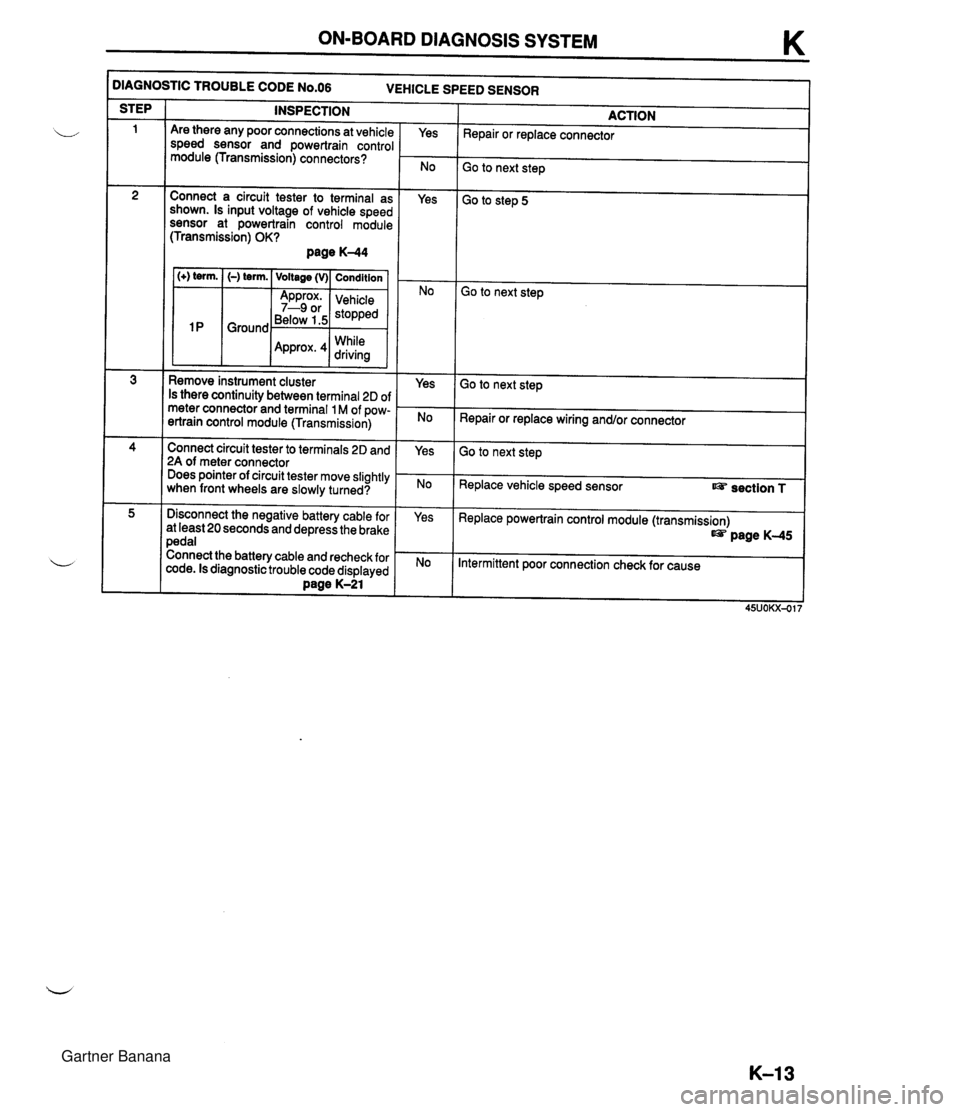
ON-BOARD DIAGNOSIS SYSTEM K )IAGNOSTIC TROUBLE CODE N0.06 VEHICLE SPEED SENSOR INSPECTION STEP ACTION Repair or replace connector Are there any poor connections at vehicle speed sensor and powertrain control module (Transmission) connectors? Yes Go to next step Connect a circuit tester to terminal as shown. Is input voltage of vehicle speed sensor at powertrain control module (Transmission) OK? page K-44 Yes Go to step 5 1 (+) term. I (-) term. ( Voltage (v)( Condition I Go to next step Below 1.5 While Remove instrument cluster Is there continuity between terminal 2D of meter connector and terminal 1 M of pow- ertrain control module (Transmission) Yes Go to next step Repair or replace wiring and/or connector Connect circuit tester to terminals 2D and 2A of meter connector Does pointer of circuit tester move slightly when front wheels are slowly turned? Yes Go to next step Replace vehicle speed sensor section T Disconnect the negative battery cable for at least 20 seconds and depress the brake pedal Connect the battery cable and recheck for code. Is diagnostic trouble code displayed Dane K-21 Yes Replace powertrain control module (transmission) page K-45 Intermittent poor connection check for cause Gartner Banana