Page 264 of 1708
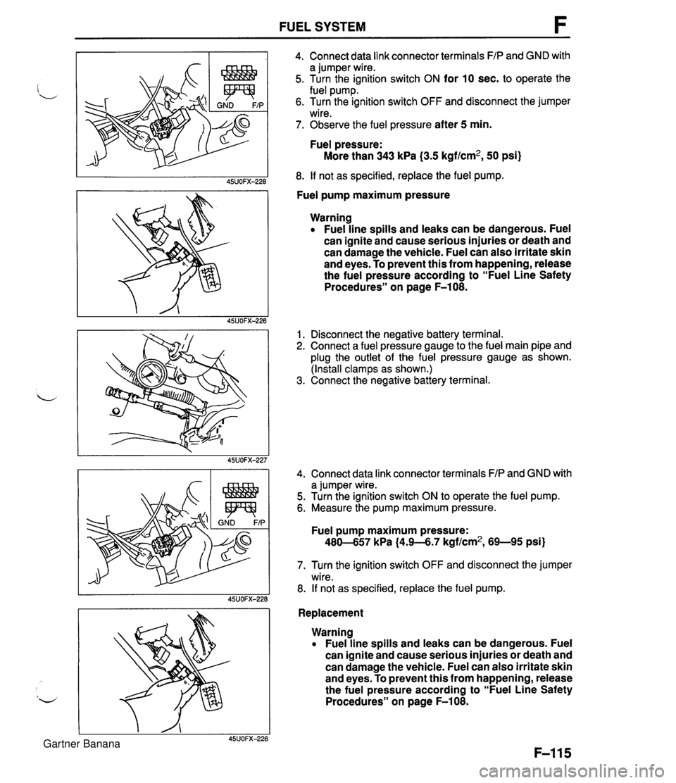
FUEL SYSTEM 4. Connect data link connector terminals FIP and GND with a jumper wire. 5. Turn the ignition switch ON for 10 sec. to operate the fuel pump. 6. Turn the ignition switch OFF and disconnect the jumper wire. 7. Observe the fuel pressure after 5 min. Fuel pressure: More than 343 kPa (3.5 kgf/cm2, 50 psi) 8. If not as specified, replace the fuel pump. Fuel pump maximum pressure Warning Fuel line spills and leaks can be dangerous. Fuel can ignite and cause serious injuries or death and can damage the vehicle. Fuel can also irritate skin and eyes. To prevent this from happening, release the fuel pressure according to "Fuel Line Safety Procedures" on page F-108. 1. Disconnect the negative battery terminal. 2. Connect a fuel pressure gauge to the fuel main pipe and plug the outlet of the fuel pressure gauge as shown. (Install clamps as shown.) 3. Connect the negative battery terminal. 4. Connect data link connector terminals FIP and GND with a jumper wire. 5. Turn the ignition switch ON to operate the fuel pump. 6. Measure the pump maximum pressure. Fuel pump maximum pressure: 480-657 kPa (4.9-6.7 kgf/cm2, 69-95 psi) 7. Turn the ignition switch OFF and disconnect the jumper wire. 8. If not as specified, replace the fuel pump. Replacement Warning Fuel line spills and leaks can be dangerous. Fuel can ignite and cause serious injuries or death and can damage the vehicle. Fuel can also irritate skin and eyes. To prevent this from happening, release the fuel pressure according to "Fuel Line Safety Procedures" on page F-108. Gartner Banana
Page 267 of 1708
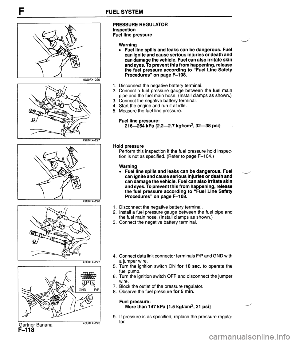
F FUEL SYSTEM PRESSURE REGULATOR Inspection Fuel line pressure d Warning Fuel line spills and leaks can be dangerous. Fuel can ignite and cause serious injuries or death and can damage the vehicle. Fuel can also irritate skin and eyes. To prevent this from happening, release the fuel pressure according to "Fuel Line Safety Procedures" on page F-108. 1. Disconnect the negative battery terminal. 2. Connect a fuel pressure gauge between the fuel main pipe and the fuel main hose. (Install clamps as shown.) 3. Connect the negative battery terminal. 4. Start the engine and run it at idle. 5. Measure the fuel line pressure. Fuel line pressure: 21 6-264 kPa (2.2-2.7 kgf/cm2, 32-38 psi) Hold pressure Perform this inspection if the fuel pressure hold inspec- tion is not as specified. (Refer to page F-104.) Warning Fuel line spills and leaks can be dangerous. Fuel ,-, can ignite and cause serious injuries or death and can damage the vehicle. Fuel can also irritate skin and eyes. To prevent this from happening, release the fuel pressure according to "Fuel Line Safety Procedures" on page F-108. 1. Disconnect the negative battery terminal. 2. Install a fuel pressure gauge between the fuel pipe and the fuel main hose. (Install clamps as shown.) 3. Connect the negative battery terminal. 4. Connect data link connector terminals F/P and GND with a jumper wire. 5. Turn the ignition switch ON for 10 sec. to operate the fuel pump. 6. Turn the ignition switch OFF and disconnect the jumper wire. 7. Block the outlet of the pressure regulator. 8. Observe the fuel pressure for 5 min. Fuel pressure: More than 147 kPa {I .5 kgf/cm2, 21 psi) 9. If pressure is as specified, replace the pressure regula- tor. Gartner Banana
Page 268 of 1708
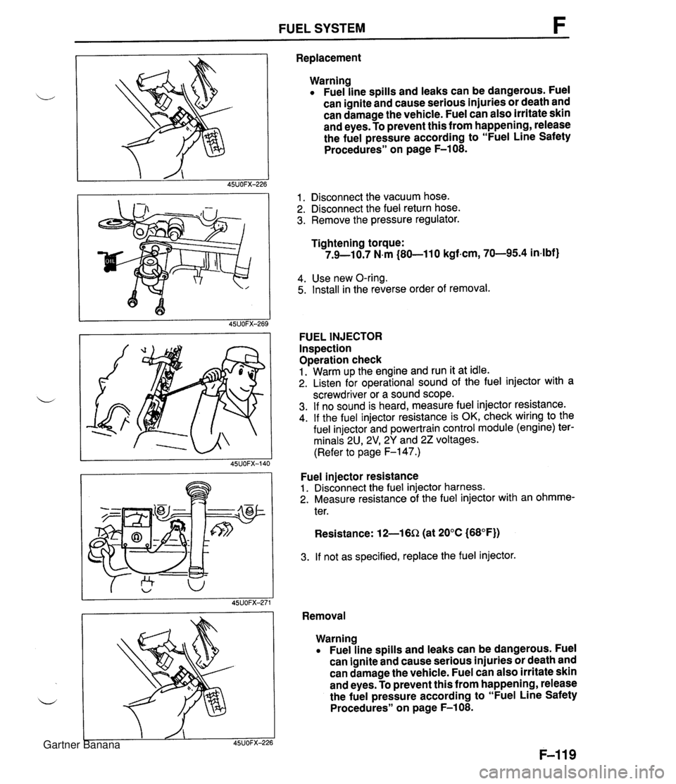
FUEL SYSTEM F Replacement Warning Fuel line spills and leaks can be dangerous. Fuel can ignite and cause serious injuries or death and can damage the vehicle. Fuel can also irritate skin and eyes. To prevent this from happening, release the fuel pressure according to "Fuel Line Safety Procedures" on page F-108. 1. Disconnect the vacuum hose. 2. Disconnect the fuel return hose. 3. Remove the pressure regulator. Tightening torque: 7.9-10.7 N.m (80-11 0 kgf-cm, 70-95.4 in4bf) 4. Use new O-ring. 5. Install in the reverse order of removal. FUEL INJECTOR Inspection Operation check 1. Warm up the engine and run it at idle. 2. Listen for operational sound of the fuel injector with a screwdriver or a sound scope. 3. If no sound is heard, measure fuel injector resistance. 4. If the fuel injector resistance is OK, check wiring to the fuel injector and powertrain control module (engine) ter- minals 2U, 2V1 2Y and 22 voltages. (Refer to page F-147.) Fuel injector resistance 1. Disconnect the fuel injector harness. 2. Measure resistance of the fuel injector with an ohmme- ter. Resistance: 12-16Q (at 20°C (68°F)) 3. If not as specified, replace the fuel injector. Removal Warning Fuel line spills and leaks can be dangerous. Fuel can ignite and cause serious injuries or death and can damage the vehicle. Fuel can also irritate skin and eyes. To prevent this from happening, release the fuel pressure according to "Fuel Line Safety Procedures" on page F-108. Gartner Banana
Page 270 of 1708
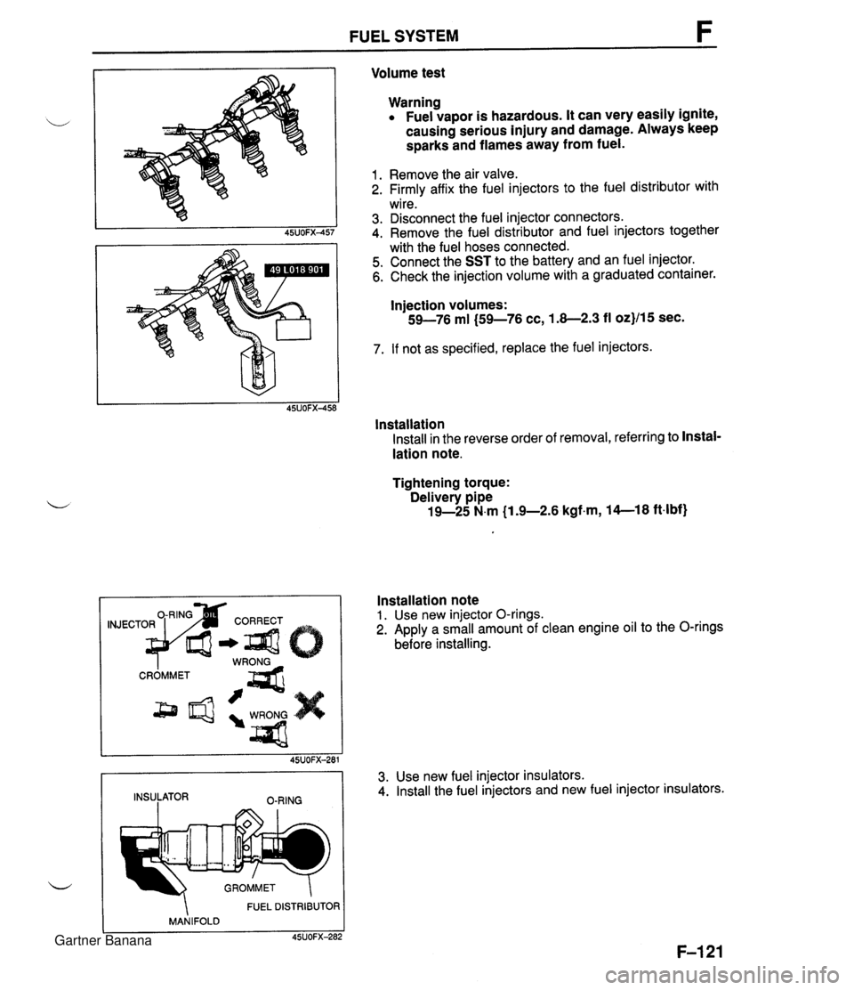
FUEL SYSTEM Volume test Warning Fuel vapor is hazardous. It can very easily ignite, causing serious injury and damage. Always keep sparks and flames away from fuel. 1. Remove the air valve. 2. Firmly affix the fuel injectors to the fuel distributor with wire. 3. Disconnect the fuel injector connectors. 4. Remove the fuel distributor and fuel injectors together with the fuel hoses connected. 5. Connect the SST to the battery and an fuel injector. 6. Check the injection volume with a graduated container. Injection volumes: 59-76 ml (59-76 cc, 1.8-2.3 fl oz}/15 sec. 7. If not as specified, replace the fuel injectors. lnstallation Install in the reverse order of removal, referring to Instal- lation note. Tightening torque: Delivery pipe 19-25 N.m (1 .%2.6 kgfm, 14--18 ft4bf) FUEL DISTRIBUTOR MANIFOLD C 45UOFX-282 Installation note 1. Use new injector O-rings. 2. Apply a small amount of clean engine oil to the O-rings before installing. 45UOFX-281 INSULATOR O-RING 3. Use new fuel injector insulators. 4. Install the fuel injectors and new fuel injector insulators. Gartner Banana
Page 302 of 1708
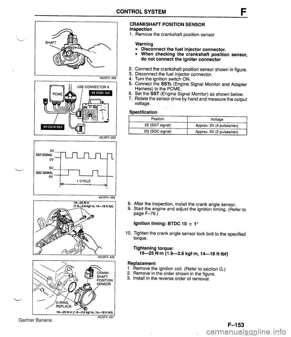
CONTROL SYSTEM 1 1 USE CONNECTOR A CRANKSHAFT POSITION SENSOR Inspection 1. Remove the crankshaft position sensor 5v- - - - SGGSIGNAL ov Warning Disconnect the fuel injector connector. When checking the crankshaft position sensor, do not connect the igniter connector - - - - I 1 CYCLE < > 2. Connect the crankshaft position sensor shown in figure. 3. Disconnect the fuel injector connector. 4. Turn the ignition switch ON. 5. Connect the SSTs (Engine Signal Monitor and Adapter Harness) to the PCME. 6. Set the SST (Engine Signal Monitor) as shown below. 7. Rotate the sensor drive by hand and measure the output voltage. Specification I 1 - Position - ~oltaael 8. After the inspection, install the crank angle sensor. 9. Start the engine and adjust the ignition timing. (Refer to page F-76.) 2E (SGT signal) 2G (SGC signal) Ignition timing: BTDC 10 2 1" Approx. 5V (4 pulseslrev) Approx. 5V (2 pulseslrev) 10. Tighten the crank angle sensor lock bolt to the specified torque. Tightening torque: 19-25 N-m (1 .+2.6 kgfem, 14-1 8 ftelbf} Replacement 1. Remove the ignition coil. (Refer to section G.) 2. Remove in the order shown in the figure. 3. Install in the reverse order of removal. Gartner Banana
Page 308 of 1708

Before beginning any service procedure. refer to section T of this manual for air bag system service warnings and audio antitheft system alarm conditions . ENGINE ELECTRICAL SYSTEM INDEX ....................................... G- 2 OUTLINE ..................................... G- 3 SPECIFICATIONS ........................... G- 3 TROUBLESHOOTING GUIDE .................. G- 4 CHARGING SYSTEM .......................... G- 6 PREPARATION ............................. G- 6 CIRCUIT DIAGRAM ......................... G- 6 TROUBLESHOOTING ....................... G- 7 BATTERY .................................. G- 8 ALTERNATOR .............................. G-10 DRIVE BELT ................................ G-13 IGNITION SYSTEM ............................ G-15 PREPARATION ............................. G-15 CIRCUIT DIAGRAM ......................... G-15 TROUBLESHOOTING ....................... G-16 IGNITION TIMING ........................... G-17 SPARK PLUG ............................... G-18 IGNITION COIL ............................. G-19 IGNITER ................................... G-19 HIGH-TENSION LEAD ....................... G-20 STARTING SYSTEM ........................... G-21 CIRCUIT DIAGRAM ......................... G-21 TROUBLESHOOTING ....................... G-21 STARTER .................................. G-22 STARTER INTERLOCK SWITCH (MT) ......... G-28 45UOGX401 Gartner Banana
Page 314 of 1708
CHARGING SYSTEM G TROUBLESHOOTING Check 1 Check if battery p Check battery (Refer to page G-8) J Check 2 I. Turn ignition switch ON Check wire harness 2. Check if voltage exists at each terminal of alternator Check 3 YES 1. Start engine Check alternator (Refer to page G-10) 2. Check if alternator warning light goes off I YES Check if drive belt t Adjust or replace drive belt (Refer to page G-14) 1 YES I Check for dark current (Refer to page G-3) I Check 1 BATTERY r"; Check 3 I ALTERNATOR WARNING LIGHT Check 2 B+: Battery positive voltage I I I B 1 Approx. 12V 1 Approx. 12V I B+ ON ON (Idle) L S 45UOGX-006 OV Approx. 12V Approx. 1V Approx. 12V B+ B+ Gartner Banana
Page 315 of 1708
CHARGING SYSTEM 1. Disconnect the battery cables from the battery. 2. Connect a voltmeter to the battery. BATTERY Warning Hydrogen gas is produced during normal battery d operation. A battery-related explosion can cause serious injury. Keep all flames (including ciga- rettes), heat, and sparks away from the top and surrounding area of open battery cells. Caution To prevent damage to electrical components or the battery, turn all accessories off and stop the engine before performing maintenance or re- charging the battery. Caution Obtain the code number and deactivate the audio anti-theft system before disconnecting the bat- tery. (Refer to section T.) Inspection Caution When disconnecting the battery, remove the neg- ative cable first and install it last to prevent dam- age to electrical components or the battery. Gartner Banana