Page 800 of 1708
s WINDSHIELD WIPER AND WASHER I mm (in) 05UOSX459 I MOLDING EDGE ' C~NTER mm (in) 05UOSx-060 CONNECTOR SHAFT Adjustment Arm height Set the arm height as shown. Washer nozzle Insert a needle or similar object into the nozzle hole and move the nozzle to adjust the spray direction. Installation Note Wiper arm and blade Clean the wiper arm connector shafts with a wire brush before installing the wiper warms. Gartner Banana
Page 812 of 1708
REAR WINDOW INSULATION TAPE RIVET MOUNTING A INSULATION TAPE INSULATION TAPE SEC. A-A THE END OF THE ZIPPER 11. Remove the rivets from the rain rail with a cutter, and remove the rain rail from the convertible top. 12. Remove the rivets from the rear window with a cutter. 13. Peel apart the Velcro. Note Save the zipper stops for reuse. 14. Carefully remove the zipper stops from the rear window ,-- and top fabric, and remove the rear window. Installation Note Rear window 1. Decrease the rain rail with ethyl alcohol. 2. Install insulation tape to the rivet mounting holes of the rain rail. Insulation tape Width : 20 mm (0.79 in) Height : 15 mm 10.59 in) Thickness : 3 mm I0.12 in) 3. Align the ends of the zipper, and install the zipper pull tab. 4. Zip the rear window into place. Gartner Banana
Page 836 of 1708
CONVERTIBLE TOP 26. Install the retainers to the link assembly, aligning the retainer marks with the retainer mounting screws. 27. Install the weatherstri~s to the link assemblv. 28. Install the convertible'to~ to the bodv. (~ef& to paae S-67.) PROTECTOR ADJUSTING NUT WINDSHIELD HEADER CONVERTIBLE TOP I Adjustment Top latch assembly 1. Lift the protector away from the top latch assembly ad- justing nut. 2. Turn the adjusting nut clockwise to decrease clearance A and height B; turn the nut counterclockwise to increase them. 3. Secure the adjusting nut with the protector. Gartner Banana
Page 840 of 1708

DETACHABLE HARDTOP PROTECTOR ADJUSTING NUT DETACHABLE HARDTOl WINDSHIELD HEADER I @ 1 5 r 2 (0.2 f 0.08) @ 1 0 r 2 (0 * 0.08) mm (in) 45UOSX-11 f Adjustment Top latch assembly 1. Lift the protector away from the top latch assembly ad- justing nut. d 2. Turn the adjusting nut clockwise to decrease clearance A and height B; turn the nut counterclockwise to increase them. 3. Secure the adjusting nut with the protector. I I Side latch assembly 1. Lift the protector away from the side latch assembly ad- justing nut. 2. Turn the adjusting nut clockwise to tighten the striker and side latch assembly engagement; turn the nut counter- clockwise to loosen the engagement. - 3. Secure the adjusting nut with the protector. ADJUSTING NUT 45UOSX-117 Rear deck latch assembly 1. Remove the screw and open the latch cover. 2. Loosen the plate mounting bolts. 3. Install the detachable hardtop to the body. 4. Move the plate right, left, fore, or aft until it is tight. 5. Tighten the plate mounting bolts. Tightening torque: 18-26 N.m (1.8-2.7 kgfsm, 14--19 ft-lbf) 6. Close the latch cover and install the screw. Gartner Banana
Page 901 of 1708
T LIGHTING SYSTEM Stoplight Switch Adjustment 1. Adjust the brake pedal height. (Refer to section P.) 2. Disconnect the stoplight switch connector. 4 3. Loosen the stoplight switch locknut. 4. Turn the stoplight switch until it contacts the pedal arm. Turn an additional 112 turn. 5. Tighten the locknut. Locknut tightening torque: 14-18 N.m (1.4-1.8 kgf-m, 120-156 in-lbf) I I I Brake pedal depress I 0 0 1 I Inspection Stoplight switch 1. Disconnect the stoplight switch connector. 2. Check for continuity between terminals of the switch. lnspection condition 3. If not as specified, replace the stoplight switch. Terminal A I B I Brake pedal released I m : Continuity Gartner Banana
Page 950 of 1708

CRUISE CONTROL SYSTEM T BRAKE AND STOPLIGHT SWITCH CLUTCH SWITCH Removal Loosen the locknut and remove the switch. Installation Install in the reverse order of removal. Adjustment Adjust the switch to set the specified pedal height. Pedal height: 175--185mm (6.89-7.82 in) Pedal free play: 0.6-3.lmm (0.02-4.12 in) Inspection 1. Disconnect the clutch switch connector. 2. Check for continuity between terminals of the switch. Pedal position Terminal A B 1 0-a: Continuity Pedal released 3. If not as specified, replace the clutch switch. Pedal de~ressed STOP LIGHTIBRAKE SWITCH Removal Loosen the locknut and remove the switch. 0 I 0 Installation Install in the reverse order of removal. Adjustment Adjust the switch to set the specified pedal height. Pedal height: l7l-l8l mm (6.93--7.13 in) Pedal free play: 4.0-7.0mm (0.16-0.28 in) Inspection 1. Disconnect the brake switch connector. 2. Check for continuity between terminals of the switch. I I I Pedal released I I I Pedal position w: Continuity Terminal Pedal depressed 3. If not as specified, replace the brake switch. 4. If the switch is OK, repair the wiring harness (fuse - brake switch - control unit). A 0 I 0 B Gartner Banana
Page 1110 of 1708

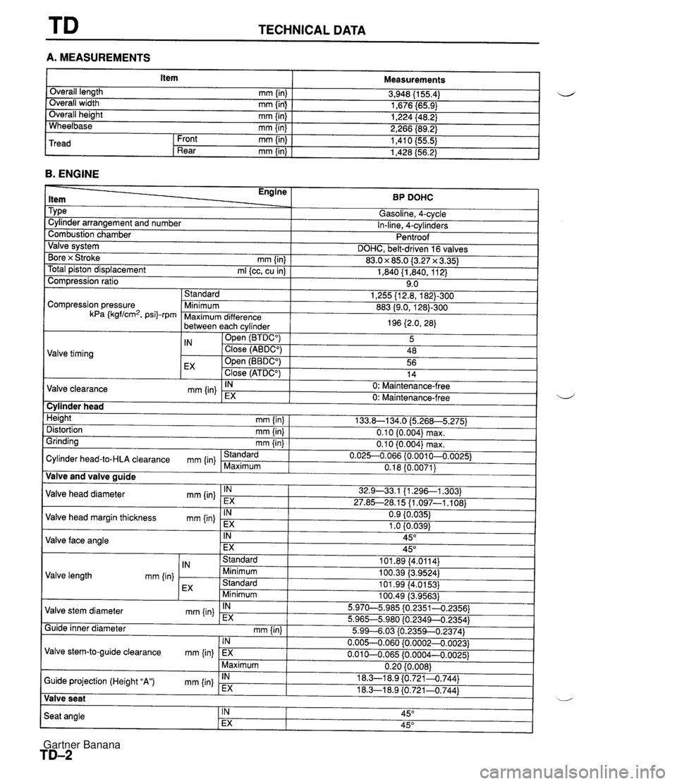
TD TECHNICAL DATA A. MEASUREMENTS I Item I Measurements I B. ENGINE Overall length mm {in) Overall width mm (in) Overall height mm {in) Wheelbase mm {in) 3,948 (1 55.4) 1,676 i65.9) 1,224 I48.2) 2,266 I89.2) 1,410 (55.5) 1,428 (56.2) Tread - ltem Tvoe u Front mm (in) Rear mm {in) BP DOHC Gasoline. 4-cvcle . In-line, 4-cylinders Pentroof DOHC, belt-driven 16 valves 83.0 x 85.0 {3.27 x 3.35) 1,840 (1,840, 11 2) 9.0 1,255 {I 2.8, 1823-300 883 (9.0, 1281-300 196 {2.0, 28) s. Cylinder arrangement and number Combustion chamber Valve system Bore x Stroke mm {in] Total piston displacement ml {cc, cu in) Compression ratio Valve timing Compression pressure kPa (kgflcm2. psil-r~m I Valve and valve auide I Standard Minimum Maximum difference between each cvlinder - - IN openz (BTDCO) Close (ABDCO) Open (BBDCO) EX close (ATDC") Valve clearance mm {in) Cylinder head 5 48 56 14 IN 133.8-1 34.0 i5.268-5.275) 0.1 0 {0.004) max. 0.10 {0.004) max. 0.02G0.066 {0.0010-0,0025) 0.18 {0.0071) Height mm (in) Distortion mm {in) Grinding mm {in) - 0: Maintenance-free Cylinder head-to-HLA clearance mm (in} Valve head diameter mm Iin) Valve head margin thickness mm {in} Valve face angle I Valve seat 1 u Standard Maximum Valve length mm {in) EX IN EX IN EX IN EX Standard Minimum Standard Minimum IN EX IN EX 5.99--6.03 iO.2359--0.2374) 0.005--0.060 (0.0002-0.0023) 0.01 b0.065 (0.0004-0,0025) 0.20 {0.008} 18.3-1 8.9 {0.7214.744) 18.3-1 8.9 (0.721-0.744) Guide inner diameter mm (in) 0: Maintenance-free 32.9-33.1 {I .296--1.303) 27.85-28.15 {I .097-1 .I 08) 0.9 {0.035) 1 .O (0.039) 45" 45" 101.89 {4.0114} 100.39 {3.9524) 101.99 (4.0153) 100.49 (3,9563) 5.970-5.985 {0.2351-0.2356) 5.96G5.980 l0.2349-0.2354) Valve stem diameter mm {in) Valve stem-to-guide clearance mm (in) Guide projection (Height "A) mm {in) Seat angle IN EX Maximum IN EX IN 45" EX 45" Gartner Banana
Page 1111 of 1708

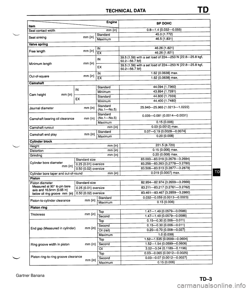
TECHNICAL DATA TD BP DOHC 0.8-1.4 {0.0324.055) 45.0 (1.772) 46.5 11.831) Engine Item Seat contact width mm {in) Valve spring End gap (Measured in cylinder) mm {in) Seat sinking mm {in) Free length mm {in) Minimum length mm {in) Out-of-square mm {in) Camshaft bearing oil clearance mm {in} Ring groove width in piston mm {in) Standard Maximum Piston ring-to-ring groove clearance mm {in) IN EX IN EX IN EX Standard (No.1-No.5) Maximum 46.26 (1.821) 46.26 (1.821) 39.5 {I 56) with a set load of 224--253 N I22.8-25.8 kgf, 50.2-56.7 Ibf) 39.5 (1 56) with a set load of 224-253 N I22.8-25.8 kgf, 50.2-56.7 Ibf) 1.62 (0.0638) max. 1.62 (0.0638) max. Camshaft 0.035-0.081 {0.0014-0..0031) 0.1 5 (0.006) 0.03 {0.001 2) max. 0.07-0.1 9 {0.002~.0074) 0.20 {0.008) Camshaft runout mm {in) TOP Second Cam height mm {in) Camshaft end play mm (in) 0.15-0.30 {0.006-0.011) 0.15-0.30 {0.006--0.011) -- - I Standard Minimum Standard Minimum Standard (No.1-N0.5) IN EX Standard Maximum Oil (rail) Maximum I 1 .O {0.039) 44.094 {I .7360) 43.894 {I .7281) 44.600 11.7559) 44.400 {I .7480) 25.940-25.965 11.021 3-1.0222) Journal diameter mm Iin) Cylinder block 0.20-0.70 {0.00&0.027) TOD Second Oil 1.52-1 535 {0.0594--0.0604) 1.52-1.54 (0.0599--0.0606} 3.02-3.04 f0.11894.1196) Second Maximum 221.5 (8.720) 0.1 5 {0.006) max. 0.20 {0.008) max. 83.00&83.019 i3.2678-3.2684) 83.25683.263 {3.277&3.2780) 83.508-883.51 3 (3.2877-3.2879) 0.01 9 {0.0007} max. Height mm {in) Distortion mm (in) Grinding mm {in} 0.03-0.07 {0.00124.0027) 0.1 5 {0.006) Cylinder bore diameter mm {in] Standard size 0.25 {0.01) oversize 0.50 (0.02) oversize Piston , Cylinder bore taper and out-of-round mm {in) 82.95442.974 i3.2659--3.2666) 83.211-43.21 7 (3.2761-3.2762) 83.461-83.467 (3.2853--3.2860) 0.0324.059 {0.001 3--0.0023) 0.15 (0.006) Piston diameter Measured at 90" to Pin bore axis and 16.5mm i0.65 in) below oil ring groove mm {in) Standard size 0.25 {0.01) oversize 0.50 (0.02) oversize Piston ring Piston-to-cylinder clearance mm (in) Thickness mm {in) Standard Maximum TOP 1.47-1 -49 (0.0579--0.0586} Second 1.47-1.49 {0.0579--0.0586) Gartner Banana