Page 1038 of 1708
SRS AIR BAG SYSTEM T Possible cause Defective S-sensor Defective wiring harness Defective diagnostic module Flowchart No.6 Step 1 Carry out "Before Servicing" procedure under GEN- ERAL PROCEDURES, page T-1 60. Step 2 1. Disconnect the diagnostic module connector. 2. Check for continuity between terminals 2C (G) and 1 H (G/B) of the diagnostic module connector. I Continuity I Action I Symptom Service Code 23 Step 3 1. Disconnect the orange and blue S-sensor connectors. 2. Check for continuity between terminals E and B of the S-sensor. Yes No Replace diagnostic module (Refer to page T-208) Go to Step 3 I No I Replace S-sensor (Refer to ~aae T-213) I Continuity Yes Action Replace wiring harness Gartner Banana
Page 1048 of 1708
SRS AIR BAG SYSTEM T Step 5 1. Disconnect the orange and blue S-sensor connectors. 2. Check for continuity between terminal C of the S-sensor and ground. Continuity Action 1 Yes Step 6 Check for continuity between terminal 1A (BFUR) of the diagnostic module connector and ground. Replace S-sensor and then replace diagnos- tic module No Replace wiring harness and then replace diag- nostic module - - I NO I Go to Step 8 Continuity Step 7 1. Disconnect the center D-sensor connector. 2. Check for continuity between terminal B of the center D-sensor and ground. Action I Continuitv Action 1 Yes I GO to ~te~ 7 Step 8 Check for continuity between terminal 2L (BR/B) of the diagnostic module connector and ground. Yes No -- Replace center D-sensor and then replace diagnostic module Replace wiring harness and then replace diag- nostic module I NO I GO to Step 10 Continuity Yes Action Go to Step 9 Gartner Banana
Page 1050 of 1708
SRS AIR BAG SYSTEM Possiblecause Defective wiring harness Defective S-sensor Defective diagnostic module Flowchart No.16 Step 1 Carry out "Before Servicing" procedure under GEN- ERAL PROCEDURES, page T-1 60. Step 2 1. Disconnect the diagnostic module connector. 2. Check for continuity between terminal 1 H (GIB) of the diagnostic module connector and ground. Continuity Action I Symptom Yes I Go to Step 3 I Service Code 52 Step 3 1. Disconnect the orange and blue S-sensor connectors. 2. Check for continuity between terminal B of the S-sensor and ground. No Replace diagnostic module (Refer to page T-208) I No 1 Re~lace wirina harness I Continuity Yes Action Replace S-sensor (Refer to page T-213) Possible cause Internal failure of diagnostic module Flowchart No.17 Remedy Replace the diagnostic module. (Refer to page T-208.) Symptom Service Code 53 Gartner Banana
Page 1051 of 1708
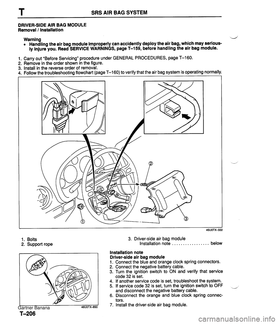
SRS AIR BAG SYSTEM DRIVER-SIDE AIR BAG MODULE Removal I Installation Warning 4 Handling the air bag module improperly can accidently deploy the air bag, which may serious- ly injure you. Read SERVICE WARNINGS, page T-159, before handling the air bag module. 1. Carry out "Before Servicing" procedure under GENERAL PROCEDURES, page T-160. 2. Remove in the order shown in the figure. 3. Install in the reverse order of removal. 4. Follow the troubleshootina flowchart (page T-160) to verify that the air bag system is operating normally. 1. Bolts 2. Support rope 3. Driver-side air bag module Installation note . . . . . . . . . . . . . . . . . below Installation note Driver-side air bag module 1. Connect the blue and orange clock spring connectors. 2. Connect the negative battery cable. 3. Turn the ignition switch to ON and verify that service code 32 is set. 4. If another service code is set, troubleshoot the system. 5. If service code 32 is set, turn the ignition switch to OFF and disconnect the negative battery cable. 6. Disconnect the orange and blue clock spring connec- tors. 7. Install the driver-side air bag module. Gartner Banana
Page 1052 of 1708
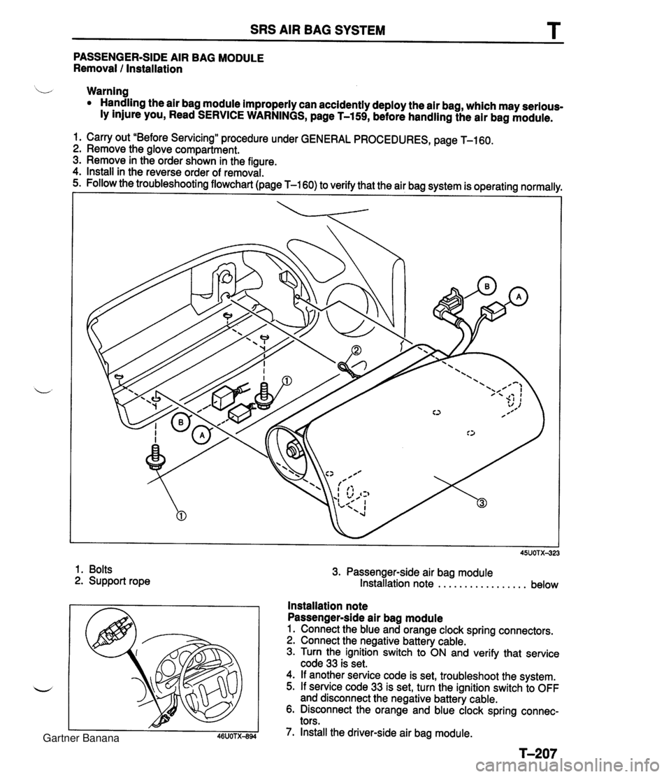
SRS AIR BAG SYSTEM T PASSENGER-SIDE AIR BAG MODULE Removal I Installation b Warning Handling the air bag module improperly can accidently deploy the air bag, which may serious- ly injure you, Read SERVICE WARNINGS, page T-159, before handling the air bag module. 1. Carry out "Before Servicing" procedure under GENERAL PROCEDURES, page T-160. 2. Remove the glove compartment. 3. Remove in the order shown in the figure. 4. Install in the reverse order of removal. 1. Bolts 2. Support rope 3. Passenger-side air bag module Installation note . . . . . . . . . . . . . . . . . below Installation note Passenger-side air bag module 1. Connect the blue and orange clock spring connectors. 2. Connect the negative battery cable. 3. Turn the ignition switch to ON and verify that service code 33 is set. 4. If another service code is set, troubleshoot the system. 5. If service code 33 is set, turn the ignition switch to OFF and disconnect the negative battery cable. 6. Disconnect the orange and blue clock spring connec- tors. 7. Install the driver-side air bag module. Gartner Banana
Page 1054 of 1708
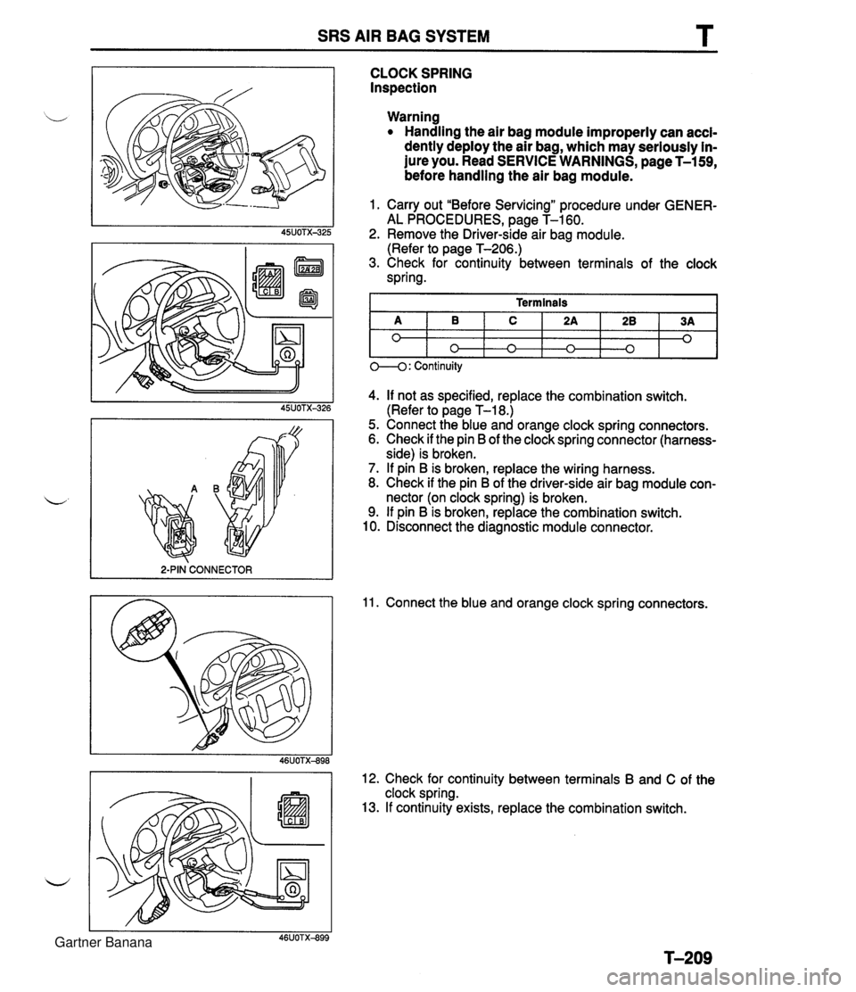
SRS AIR BAG SYSTEM T 2-PIN CONNECTOR I CLOCK SPRING Inspection Warning Handling the air bag module improperly can accl- dently deploy the air bag, which may seriously in- jure you. Read SERVICE WARNINGS, page T-159, before handling the air bag module. 1. Carry out "Before Servicing" procedure under GENER- AL PROCEDURES, page T-160. 2. Remove the Driver-side air bag module. (Refer to page T-206.) 3. Check for continuity between terminals of the clock spring. 4. If not as specified, replace the combination switch. (Refer to page T-18.) 5. Connect the blue and orange clock spring connectors. 6. Check if the pin B of the clock spring connector (harness- side) is broken. 7. If pin B is broken, replace the wiring harness. 8. Check if the pin B of the driver-side air bag module con- nector (on clock spring) is broken. 9. If pin B is broken, replace the combination switch. 10. Disconnect the diagnostic module connector. Terminals 11. Connect the blue and orange clock spring connectors. A 0 12. Check for continuity between terminals B and C of the clock spring. 13. If continuity exists, replace the combination switch. 1 0---0: Continuity B 0 C n 2A n 28 0 3A 0 Gartner Banana
Page 1060 of 1708
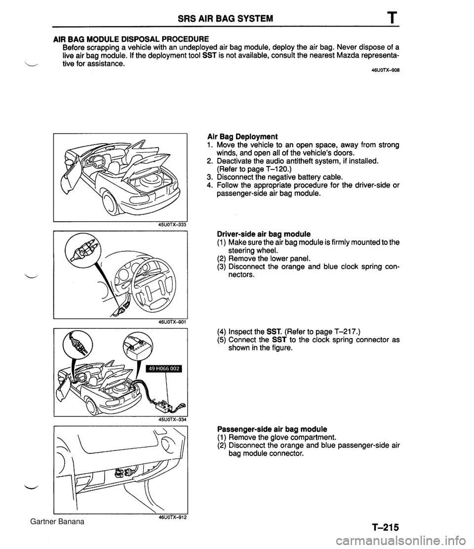
SRS AIR BAG SYSTEM T AIR BAG MODULE DISPOSAL PROCEDURE Before scrapping a vehicle with an undeployed air bag module, deploy the air bag. Never dispose of a live air bag module. If the deployment tool SST is not available, consult the nearest Mazda representa- i/ tive for assistance. 46UOTX-908 Air Bag Deployment 1. Move the vehicle to an open space, away from strong winds, and open all of the vehicle's doors. 2. Deactivate the audio antitheft system, if installed. (Refer to page T-120.) 3. Disconnect the negative battery cable. 4. Follow the appropriate procedure for the driver-side or passenger-side air bag module. Driver-side air bag module (1 ) Make sure the air bag module is firmly mounted to the steering wheel. (2) Remove the lower panel. (3) Disconnect the orange and blue clock spring con- nectors. (4) Inspect the SST. (Refer to page T-217.) (5) Connect the SST to the clock spring connector as shown in the figure. Passenger-side air bag module (1) Remove the glove compartment. (2) Disconnect the orange and blue passenger-side air bag module connector. Gartner Banana
Page 1122 of 1708
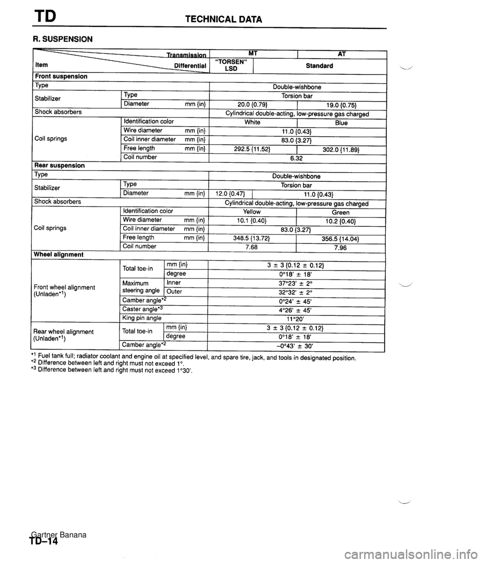
TECHNICAL DATA R. SUSPENSION Front sus~ension I i/ Differential - . - ~- Coil springs MT I AT Shock absorbers "TORSEN" LSD TY ~a Cylindrical double-acting, low-pressure gas charged Standard Stabilizer Double-wishbone Torsion bar Wire diameter mm {in) Coil inner diameter mm {in} Rear suspension Tv~e I Double-wishbone TY pe Diameter mm {in) 20.0 (0.79) I Identification color 11 .O {0.43} 83.0 f3.27) . . Free length mm {in) Coil number 19.0 {0.75} . . 292.5 (1 1.52) 1 302.0 {I 1.89) 6.32 I - . I1 . ,I . , I Shock absorbers Cylindrical double-acting, low-pressure gas charged White I I Identification color I Yellow I Green I Blue Torsion bar 12.0 (0.471 1 11 .O 10.43) .a Stabilizer TYPe Diameter mm {in) Coil springs Wheel alignment I Front wheel alignment (Unladen'') I I - Caster angle*3 King pin angle I tun'aoen 'I 1 Camber angle'2 -0°43' 2 30' I I - Wire diameter mm {in) Coil inner diameter mm {in) Free length mm {in} Coil number Maximum steering angle 4O26' -c 45' 11 "20' Rear wheel alignment ,, l-l_A_-*i, *1 Fuel tank full; radiator coolant and engine oil at specified level, and spare tire, jack, and tools in designated position. *2 Difference between left and right must not exceed lo. *3 Difference between left and right must not exceed 1'30'. 10.1 (0.40) Inner Outer 10.2 I0.40) mm (in) Camber ana~e*~ J 3 + 3 10.12 r 0.12) 0°18' 2 18' -. - 3 r 3 {0.12 2 0.12) 0'24' 2 45' 37O23' 2 2" 32O32' 2 2" Total toe-in 83.0 i3.27) U' mm {in} degree 348.5 113.72) Total toe-in 356.5 {I 4.04) dearee 7.68 0'18' & 18' 7.96 Gartner Banana