Page 1088 of 1708

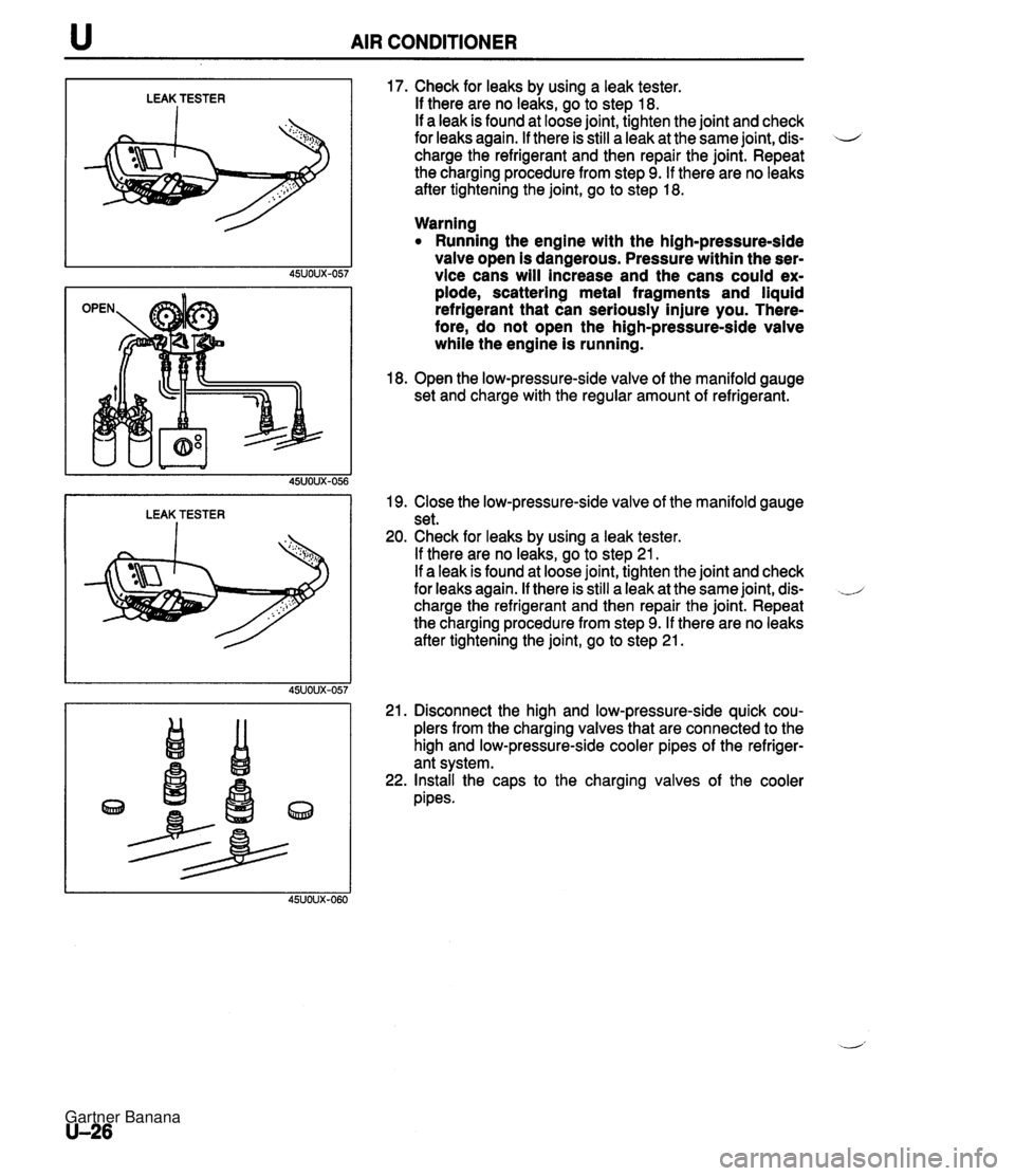
u AIR CONDITIONER LEAK TESTER I LEAK TESTER I 17. Check for leaks by using a leak tester. If there are no leaks, go to step 18. If a leak is found at loose joint, tighten the joint and check for leaks again. If there is still a leak at the same joint, dis- 4 charge the refrigerant and then repair the joint. Repeat the charging procedure from step 9. If there are no leaks after tightening the joint, go to step 18. Warning Running the engine with the high-pressure-side valve open is dangerous. Pressure within the ser- vice cans will increase and the cans could ex- plode, scattering metal fragments and liquid refrigerant that can seriously injure you. There- fore, do not open the high-pressure-side valve while the engine is running. 18. Open the low-pressure-side valve of the manifold gauge set and charge with the regular amount of refrigerant. 19. Close the low-pressure-side valve of the manifold gauge set. 20. Check for leaks by using a leak tester. If there are no leaks, go to step 21. If a leak is found at loose joint, tighten the joint and check for leaks again. If there is still a leak at the same joint, dis- charge the refrigerant and then repair the joint. Repeat the charging procedure from step 9. If there are no leaks after tightening the joint, go to step 21. 21. Disconnect the high and low-pressure-side quick cou- plers from the charging valves that are connected to the high and low-pressure-side cooler pipes of the refriger- ant system. 22. Install the caps to the charging valves of the cooler pipes. Gartner Banana
Page 1089 of 1708

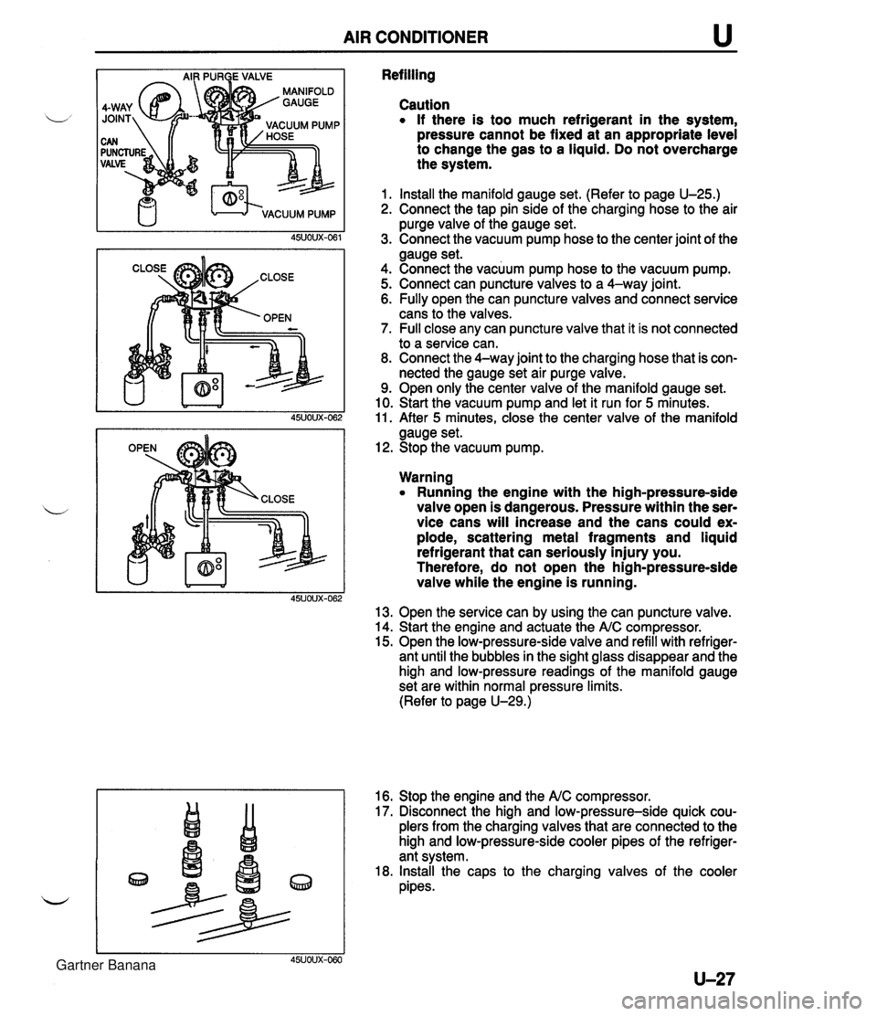
AIR CONDITIONER u Refilling Caution If there is too much refrigerant in the system, pressure cannot be fixed at an appropriate level to change the gas to a liquid. Do not overcharge the system. 1. Install the manifold gauge set. (Refer to page U-25.) 2. Connect the tap pin side of the charging hose to the air purge valve of the gauge set. 3. Connect the vacuum pump hose to the center joint of the gauge set. 4. Connect the vacuum pump hose to the vacuum pump. 5. Connect can puncture valves to a 4-way joint. 6. Fully open the can puncture valves and connect service cans to the valves. 7. Full close any can puncture valve that it is not connected to a service can. 8. Connect the 4-way joint to the charging hose that is con- nected the gauge set air purge valve. 9. Open only the center valve of the manifold gauge set. 10. Start the vacuum pump and let it run for 5 minutes. 11. After 5 minutes, close the center valve of the manifold gauge set. 12. Stop the vacuum pump. Warning Running the engine with the high-pressure-side valve open is dangerous. Pressure within the ser- vice cans will increase and the cans could ex- plode, scattering metal fragments and liquid refrigerant that can seriously injury you. Therefore, do not open the high-pressure-side valve while the engine is running. 13. Open the service can by using the can puncture valve. 14. Start the engine and actuate the A/C compressor. 15. Open the low-pressure-side valve and refill with refriger- ant until the bubbles in the sight glass disappear and the high and low-pressure readings of the manifold gauge set are within normal pressure limits. (Refer to page U-29.) 16. Stop the engine and the NC compressor. 17. Disconnect the high and low-pressure-side quick cou- plers from the charging valves that are connected to the high and low-pressure-side cooler pipes of the refriger- ant system. 18. Install the caps to the charging valves of the cooler pipes. 45UOUX-060 Gartner Banana
Page 1099 of 1708

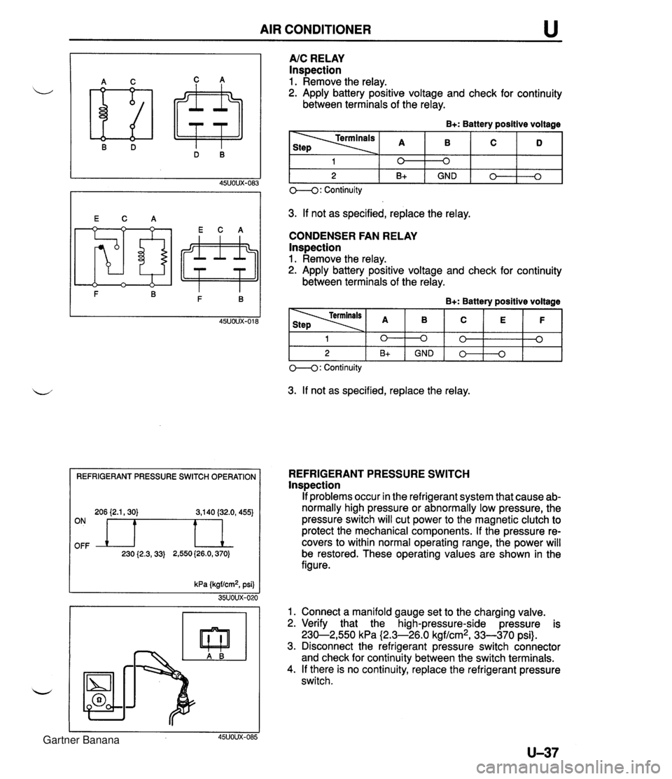
AIR CONDITIONER REFRIGERANT PRESSURE SWITCH OPERATION 206 {2.1,30) 3,140 (32.0, 455) OFF ON n 230 {2.3,33) 2,550 (26.0,370) A/C RELAY Inspection 1. Remove the relay. 2. Apply battery positive voltage and check for continuity between terminals of the relay. B+: Battery positive voltage 3. If not as specified, replace the relay. CONDENSER FAN RELAY lnspection 1. Remove the relay. 2. Apply battery positive voltage and check for continuity between terminals of the relay. B+: Battery positive voltage 1 2 O--(): Continuity 3. If not as specified, replace the relay. 0 B+ 1 2 REFRIGERANT PRESSURE SWITCH lnspection If problems occur in the refrigerant system that cause ab- normally high pressure or abnormally low pressure, the pressure switch will cut power to the magnetic clutch to protect the mechanical components. If the pressure re- covers to within normal operating range, the power will be restored. These operating values are shown in the figure. kPa (kgf/cm2, psi) 35UOUX-020 1. Connect a manifold gauge set to the charging valve. 2. Verify that the high-pressure-side pressure is 230-2,550 kPa (2.3-26.0 kgf/cm2, 33-370 psi). 3. Disconnect the refrigerant pressure switch connector and check for continuity between the switch terminals. 4. If there is no continuity, replace the refrigerant pressure switch. 45UOUX-085 0 GND 0 B+ 0 0 GND 0 0 0 0 3 Gartner Banana
Page:
< prev 1-8 9-16 17-24