Page 317 of 1708
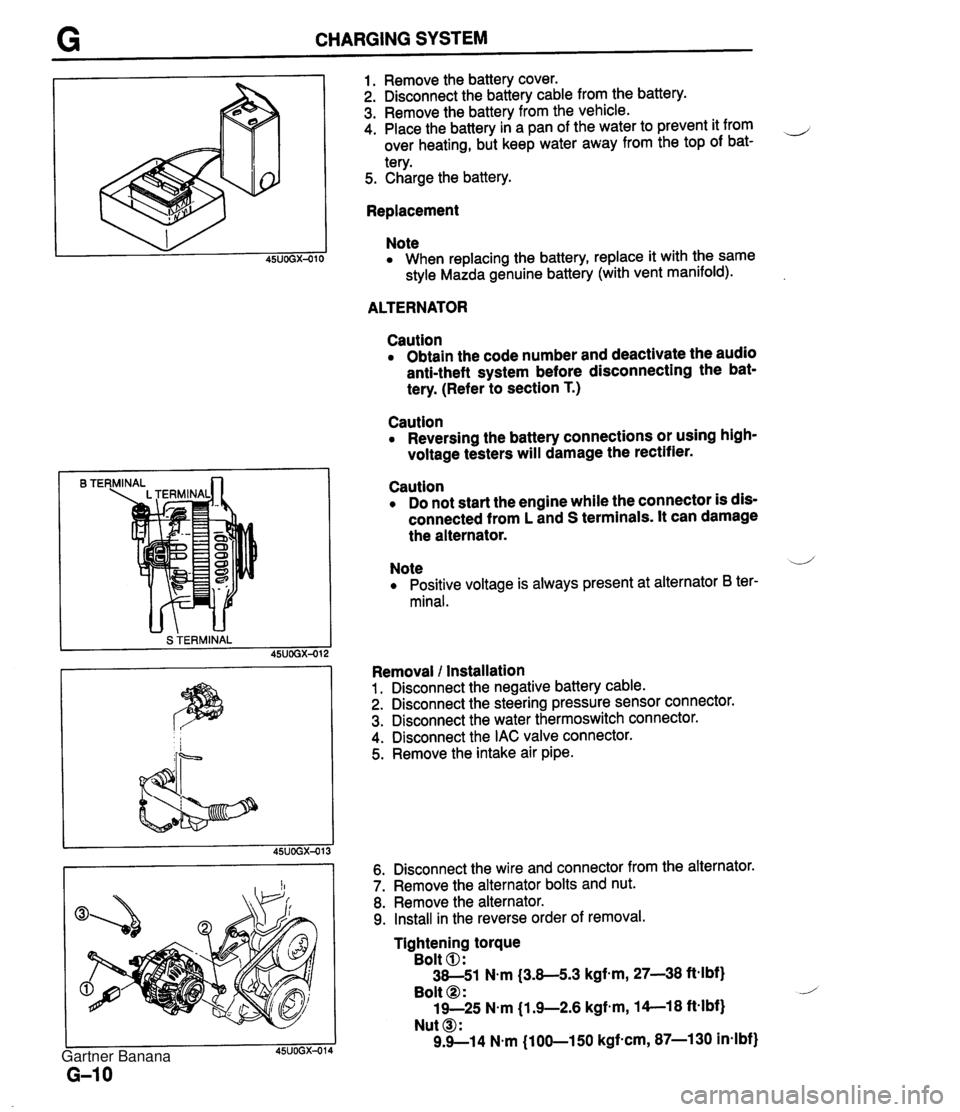
CHARGING SYSTEM B TE S TERMINAL 1. Remove the battery cover. 2. Disconnect the battery cable from the battery. 3. Remove the battery from the vehicle. 4. Place the battery in a pan of the water to prevent it from ,-, over heating, but keep water away from the top of bat- tery. 5. Charge the battery. Replacement Note When replacing the battery, replace it with the same style Mazda genuine battery (with vent manifold). ALTERNATOR Caution Obtain the code number and deactivate the audio anti-theft system before disconnecting the bat- tery. (Refer to section T.) Caution Reversing the battery connections or using high- voltage testers will damage the rectifier. Caution Do not start the engine while the connector is dis- connected from L and S terminals. It can damage the alternator. Note .--,' Positive voltage is always present at alternator B ter- minal. Removal l Installation 1. Disconnect the negative battery cable. 2. Disconnect the steering pressure sensor connector. 3. Disconnect the water thermoswitch connector. 4. Disconnect the IAC valve connector. 5. Remove the intake air pipe. 6. Disconnect the wire and connector from the alternator. 7. Remove the alternator bolts and nut. 8. Remove the alternator. 9. Install in the reverse order of removal. Tightening torque Bolt 0: 38-51 N.m (3.8-5.3 kgf-m, 27-38 ftelbf) Bolt @ : 19-25 N.m j1.9-2.6 kgfem, 14--18 ft-lbf) Nut @I: 9.9--14 N.m (100-150 kgf-cm, 87-1 30 in-lbf) Gartner Banana
Page 318 of 1708
CHARGING SYSTEM G Disassembly / Assembly 1. Disassemble in the order shown in the figure. 2. Assemble in the reverse order of disassembly. i/ 1. Pulley nut 6. Brush holder assembly 2. Pulley 7. Brush 3. Front cover Inspection ................. page G-12 4. Rotor 8. Rectifier Inspection ................. page G-12 Inspection ................. page G-13 5. Stator 9. Rear cover Inspection ................. page G-12 Gartner Banana
Page 319 of 1708
G CHARGING SYSTEM WEAR LIMIT LINE Inspection Rotor 1. Winding damage (1) Check the resistance between the slip rings with an J ohmmeter. Specification: 3.5--4.5SU20°C (68°F) (2) If it is not within specification, replace the rotor. 2. Ground of field coil (1) Check for continuity between each slip ring and the core with an ohmmeter. (2) Replace the rotor if there is continuity. 3. Slip ring surface If the slip ring surface is rough, use fine sandpaper to repair it. Stator 1. Wiring damage (1) Check for continuity between the stator coil leads with an ohmmeter. (2) Replace the stator if there is no continuity. 2. Ground of stator coil (1)~heck for no continuity between the stator coil leads and the core with an ohmmeter. (2) Replace the stator if there is continuity. Brush If the brushes are worn almost to or beyond the limit, replace them. Standard: 21.5mm (0.846 in) Minimum: 8.0mm (0.31 in) Gartner Banana
Page 320 of 1708
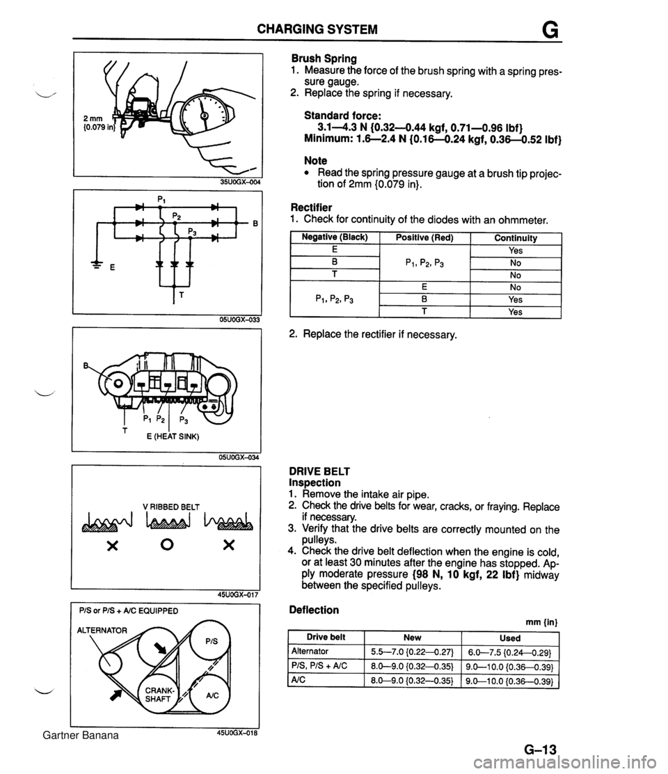
CHARGING SYSTEM G * ttt I E (HEAT SINK) 05UOGX-034 V RIBBED BELT X 0 X Brush Spring 1. Measure the force of the brush spring with a spring pres- sure gauge. 2. Replace the spring if necessary. Standard force: 3.14.3 N (0.32-444 kgf, 0.71-0.96 Ibf) Minimum: 1.6--2.4 N (0.16-0.24 kgf, 0.36-0.52 Ibf) Note Read the spring pressure gauge at a brush tip projec- tion of 2mm (0.079 in). Rectifier 1. Check for continuity of the diodes with an ohmmeter. I Negative (Black) I Positive (Red) I Continuity 1 I E I I Yes I -- 2. Replace the rectifier if necessary. DRIVE BELT Inspection 1. Remove the intake air pipe. 2. Check the drive belts for wear, cracks, or fraying. Replace if necessary. 3. Verify that the drive belts are correctly mounted on the pulleys. 4. Check the drive belt deflection when the engine is cold, or at least 30 minutes after the engine has stopped. Ap- ply moderate pressure (98 N, 10 kgf, 22 Ibf) midway between the specified pulleys. Deflection mm {in) I Drive belt New Used Alternator PIS, PIS + A/C 5.b7.0 {0.224.27) 8.0-9.0 iO.32-0.35) 6.W7.5 (0.24--0.29) 9.0-1 0.0 {0.36-0.391 Gartner Banana
Page 321 of 1708
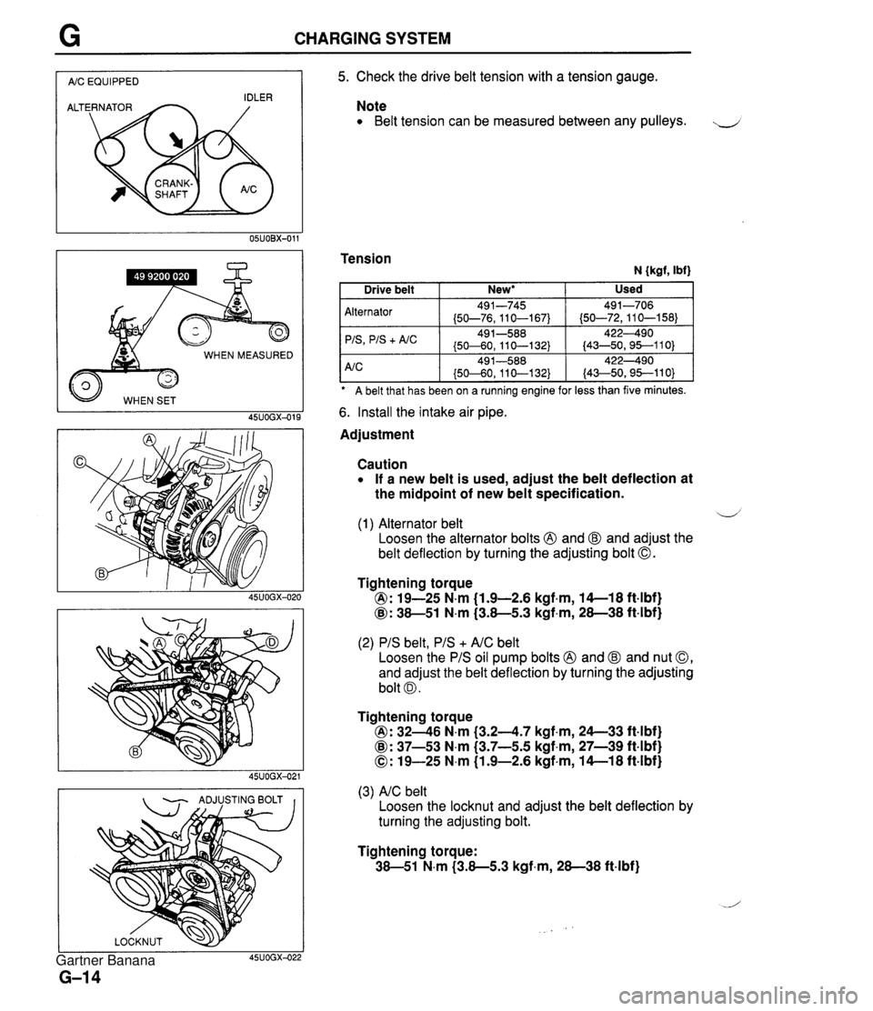
CHARGING SYSTEM I AIC EQUIPPED I WHEN MEASURED 45UOGX-015 - ADJUSTING BOLT I I 5. Check the drive belt tension with a tension gauge. Note Belt tension can be measured between any pulleys. J Tension N {kgf, Ibf) A belt that has been on a ruining engine for less than five minutes. Alternator 'IS
+ A/C 6. Install the intake air pipe. Used Drive belt Adjustment New* I Caution If a new belt is used, adjust the belt deflection at the midpoint of new belt specification. 491-745 (50-76,110-167) 49 1-588 (50-60, 11 0-1 32) d (1) Alternator belt Loosen the alternator bolts @ and @ and adjust the belt deflection by turning the adjusting bolt 0. 491-706 (50-72,110-158) 422490 (43-50,95--110) Tightening torque @: 19-25 N.m (1.9-2.6 kgf.m, 14-1 8 ft4bf) @: 38-51 N.m (3.8-5.3 kgf,m, 28-38 ft-lbf) (2) PIS belt, PIS + AIC belt Loosen the PIS oil pump bolts @ and @ and nut 0, and adjust the belt deflection by turning the adjusting bolt 0. Tightening torque @: 3246 N.m (3.24.7 kgf.m, 24--33 ft4bf) @: 37-53 N.m (3.7-5.5 kgf,m, 27-39 ft-lbf) 0: 19-25 N.m (1.9-2.6 kgf-m, 14-1 8 ft-lbf) (3) AIC belt Loosen the locknut and adjust the belt deflection by turning the adjusting bolt. Tightening torque: 38-51 N.m (3.8-5.3 kgf-m, 28-38 ft-lbf) Gartner Banana
Page 1074 of 1708
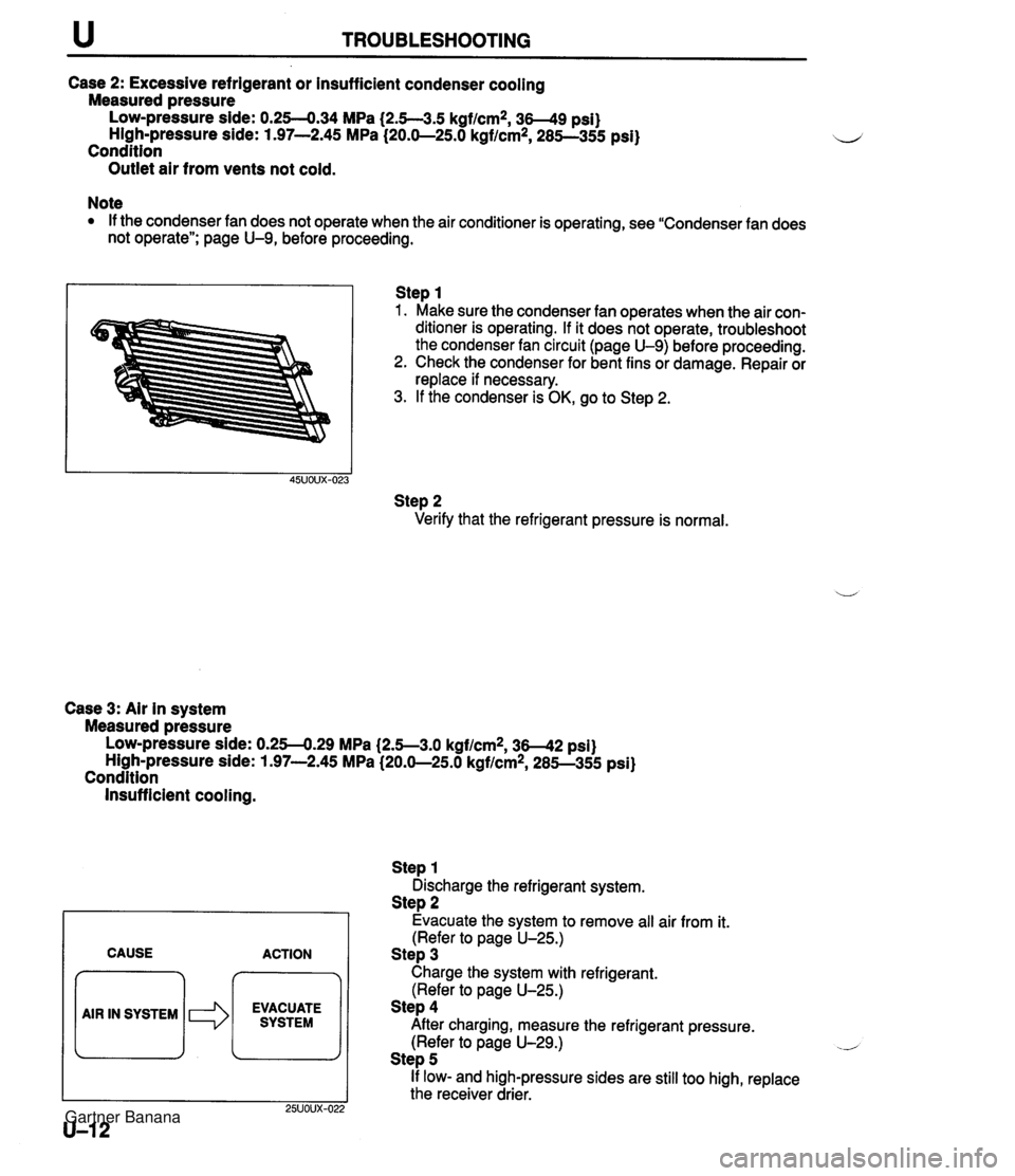
TROUBLESHOOTING Case 2: Excessive refrigerant or insufficient condenser cooling Measured pressure Low-pressure side: 0.254.34 MPa (2.5--3.5 kgf/cm2, 3-9 psi) High-pressure side: 1.97-2.45 MPa (20.0-25.0 kgflcm*, 285--355 psi) Condition Outlet air from vents not cold. Note If the condenser fan does not operate when the air conditioner is operating, see "Condenser fan does not operate"; page U-9, before proceeding. Step 1 1. Make sure the condenser fan operates when the air con- ditioner is operating. If it does not operate, troubleshoot the condenser fan circuit (page U-9) before proceeding. 2. Check the condenser for bent fins or damage. Repair or replace if necessary. 3. If the condenser is OK, go to Step 2. Step 2 Verify that the refrigerant pressure is normal. Case 3: Air in system Measured pressure Low-pressure side: 0.254.29 MPa (2.5--3.0 kgflcmz, 36-42 psi) High-pressure side: 1.97-2.45 MPa (20.0-25.0 kgf/cm2, 285--355 psi) Condition Insufficient cooling. CAUSE ACTION 7 EVACUATE SYSTEM Step 1 Discharge the refrigerant system. Step 2 Evacuate the system to remove all air from it. (Refer to page U-25.) Step 3 Charge the system with refrigerant. (Refer to page U-25.) Step 4 After charging, measure the refrigerant pressure. (Refer to page U-29.) .- Step 5 If low- and high-pressure sides are still too high, replace the receiver drier. Gartner Banana
Page 1075 of 1708
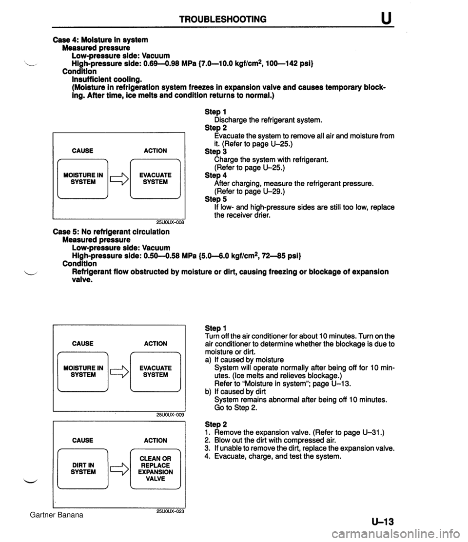
TROUBLESHOOTING Case 4: Moisture in system Measured pressure Low-pressure side: Vacuum High-pressure side: 0.69-4.98 MPa (7.O-lO.O kgf/cm2, 100-1 42 psi) Condition Insufficient cooling. (Moisture in refrigeration system freezes in expansion vaive and causes temporary block- ing. After time, ice melts and condition returns to normal.) CAUSE n MOISTURE IN I SYSTEM le ACTION EVACUATE SYSTEM Step 1 Discharge the refrigerant system. Step 2 Evacuate the system to remove all air and moisture from it. (Refer to page U-25.) Step 3 Charge the system with refrigerant. (Refer to page U-25.) Step 4 After charging, measure the refrigerant pressure. (Refer to page U-29.) Step 5 if low- and high-pressure sides are still too low, replace the receiver drier. Case 5: No refrigerant circulation Measured pressure Low-pressure side: Vacuum ~ighLpressure side: 0.50--0.58 MPa (5.0--6.0 kgf/cm2, 72-45 psi) Condition b Refrigerant flow obstructed by moisture or dirt, causing freezing or blockage of expansion valve. CAUSE ACTION MOISTURE IN CAUSE ACTION Step 1 Turn off the air conditioner for about 10 minutes. Turn on the air conditioner to determine whether the biockage is due to moisture or dirt. a) If caused by moisture System will operate normally after being off for 10 min- utes. (Ice melts and relieves blockage.) Refer to "Moisture in system"; page U-13. b) If caused by dirt System remains abnormal after being off 10 minutes. Go to Step 2. DIRT IN SYSTEM Step 2 1. Remove the expansion valve. (Refer to page U-31.) 2. Blow out the dirt with compressed air. 3. If unable to remove the dirt, replace the expansion valve. 4. Evacuate, charge, and test the system. CLEAN OR REPLACE EXPANSION VALVE Gartner Banana
Page 1087 of 1708
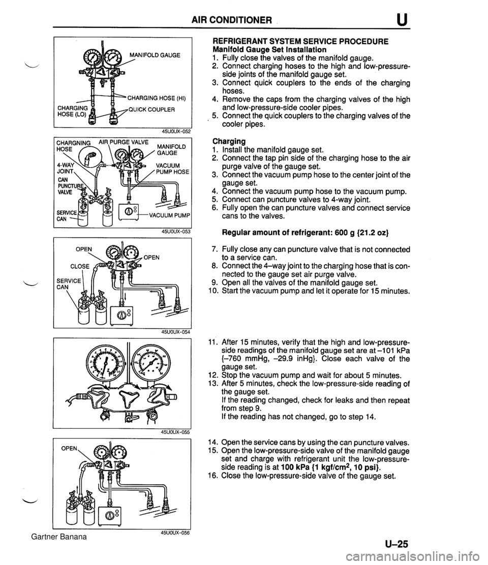
AIR CONDITIONER u NIFOLD GAUGE CHARGING HOSE (HI) QUICK COUPLER REFRIGERANT SYSTEM SERVICE PROCEDURE Manifold Gauge Set Installation 1. Fully close the valves of the manifold gauge. 2. Connect charging hoses to the high and low-pressure- side joints of the manifold gauge set. 3. Connect quick couplers to the ends of the charging hoses. 4. Remove the caps from the charging valves of the high and low-pressure-side cooler pipes. 5. Connect the quick couplers to the charging valves of the cooler pipes. Charging 1. Install the manifold gauge set. 2. Connect the tap pin side of the charging hose to the air purge valve of the gauge set. 3. Connect the vacuum pump hose to the center joint of the gauge set. 4. Connect the vacuum pump hose to the vacuum pump. 5. Connect can puncture valves to 4-way joint. 6. Fully open the can puncture valves and connect service cans to the valves. Regular amount of refrigerant: 600 g (21.2 oz) 7. Fully close any can puncture valve that is not connected to a service can. 8. Connect the 4-way joint to the charging hose that is con- nected to the gauge set air purge valve. 9. Open all the valves of the manifold gauge set. 10. Start the vacuum pump and let it operate for 15 minutes. 11'. After 15 minutes, verify that the high and low-pressure- side readings of the manifold gauge set are at -1 01 kPa {-760 mmHg, -29.9 inHg}. Close each valve of the gauge set. 12. Stop the vacuum pump and wait for about 5 minutes. 13. After 5 minutes, check the low-pressure-side reading of the gauge set. If the reading changed, check for leaks and then repeat from step 9. If the reading has not changed, go to step 14. 14. Open the service cans by using the can puncture valves. 15. Open the low-pressure-side valve of the manifold gauge set and charge with refrigerant unit the low-pressure- side reading is at 100 kPa (1 kgf/cm2, 10 psi). 16. Close the low-pressure-side valve of the gauge set. Gartner Banana